EP4506168A1 - Caoutchouc racleur, tête de racle et système de racle - Google Patents
Caoutchouc racleur, tête de racle et système de racle Download PDFInfo
- Publication number
- EP4506168A1 EP4506168A1 EP24020263.0A EP24020263A EP4506168A1 EP 4506168 A1 EP4506168 A1 EP 4506168A1 EP 24020263 A EP24020263 A EP 24020263A EP 4506168 A1 EP4506168 A1 EP 4506168A1
- Authority
- EP
- European Patent Office
- Prior art keywords
- squeegee
- bolt
- head
- rubber
- squeegee rubber
- Prior art date
- Legal status (The legal status is an assumption and is not a legal conclusion. Google has not performed a legal analysis and makes no representation as to the accuracy of the status listed.)
- Pending
Links
Images




Classifications
-
- B—PERFORMING OPERATIONS; TRANSPORTING
- B41—PRINTING; LINING MACHINES; TYPEWRITERS; STAMPS
- B41F—PRINTING MACHINES OR PRESSES
- B41F15/00—Screen printers
- B41F15/14—Details
- B41F15/44—Squeegees or doctors
-
- B—PERFORMING OPERATIONS; TRANSPORTING
- B41—PRINTING; LINING MACHINES; TYPEWRITERS; STAMPS
- B41F—PRINTING MACHINES OR PRESSES
- B41F15/00—Screen printers
- B41F15/14—Details
- B41F15/34—Screens, Frames; Holders therefor
- B41F15/36—Screens, Frames; Holders therefor flat
-
- B—PERFORMING OPERATIONS; TRANSPORTING
- B41—PRINTING; LINING MACHINES; TYPEWRITERS; STAMPS
- B41F—PRINTING MACHINES OR PRESSES
- B41F15/00—Screen printers
- B41F15/14—Details
- B41F15/40—Inking units
- B41F15/42—Inking units comprising squeegees or doctors
Definitions
- the present invention relates to a specially designed squeegee rubber, a squeegee head with this squeegee rubber and a squeegee system which has the squeegee head.
- Squeegee systems have long been known in screen printing for printing objects and workpieces using the screen printing process.
- a squeegee rubber is used to spread ink through a screen in order to apply a motif to the object to be printed.
- the flexible squeegee rubber is clamped between movable holding strips arranged next to one another in order to be able to follow the contour of the surface to be printed and achieve an even printing result.
- a spring squeegee system which is designed to enable error-free printing results even on uneven surfaces.
- the squeegee rubber is clamped into holders which are guided in the squeegee head so that they can be moved in the direction of pressure.
- a contact force of the squeegee rubber on the screen is achieved using one spring per holder. This means that the pressure on the screen is independent of the elasticity of the squeegee rubber.
- Another effect is that narrower squeegee rubbers can be used, which are much more flexible than when using squeegee rubbers which were used to transfer pressure.
- the spring tension of each individual spring can be adjusted using a lock nut.
- the present invention is therefore based on the object of overcoming the disadvantages of the prior art and providing a flexible squeegee rubber and a squeegee head with optimized guidance of the squeegee rubber, with which higher print qualities can be achieved with shorter set-up times.
- a new system is also to be provided with which soft and/or flexible bodies can also be printed.
- squeegee rubber is understood to mean an element made of a flexible material such as rubber, caoutchouc, silicone, polyurethane or the like, which has a substantially rectangular cross-section.
- the thickness of the squeegee rubber (1) is in particular less than its height. A thickness of 4 mm and a height of 5 mm are particularly preferred.
- the length of the squeegee rubber (1) depends on the intended use and the tool used.
- the "squeegee edge" is the side of the squeegee rubber (1) which is placed on the printing screen, which is located above the body to be printed.
- the “length b1" of the recesses (101) extends in the longitudinal direction of the squeegee rubber (1), the “depth t1" of the recesses (101) extends in the direction of the squeegee edge (105).
- the squeegee rubber (1) according to the invention has the advantage over conventional squeegee rubbers according to the prior art that the recesses (101) can accommodate an engagement device (303) on a squeegee head (3), so that the squeegee rubber (1) is mounted without slipping and cannot move during use.
- the recesses (101) can in particular have a length b1 that essentially corresponds to the width of the support surface (301f) of the engagement devices (303). Specifically, the width of the support surface (301f) is reduced by the concave formations (301k) to such an extent that it is the same size or slightly smaller than the recesses (101) with the length b1 and the depth t1.
- the squeegee rubber (1) further comprises grooves (103) of length b2 and depth t2 in the longitudinal direction of the squeegee rubber (1) for increasing the flexibility of the squeegee rubber (1) in the longitudinal direction, which grooves are arranged between the recesses (101).
- the “length b2" of the grooves (103) extends in the longitudinal direction of the squeegee rubber (1), the “depth t2" of the grooves (103) extends in the direction of the squeegee edge (105).
- squeegee head refers to a device which receives a squeegee rubber (1) in corresponding engagement devices (303) and supports it in a spring-loaded manner so that the squeegee rubber (1) evenly applies the screen to the body to be printed.
- several squeegee heads (3) are mounted next to one another, depending on the height of the print image to be applied to the body to be printed.
- the length of the squeegee rubber (1) is preferably 5 mm longer than the print image to be applied.
- the "bolts” serve with their engagement device (303) to hold the squeegee rubber (1), while the shaft (301s) of each bolt (301) is spring-mounted in the base body (305), is guided through the bolt guide (307) and presses the squeegee rubber (1) against the printing screen, which is located above the body to be printed.
- the bolt (301) has a thread at its end opposite the engagement device (303), onto which a securing element (319) can be screwed, the cross-section of which is slightly larger than the shaft (301s) of each bolt (301). This prevents the bolt from slipping downwards through the bolt guide (307) towards the body to be printed.
- the securing element (319) is guided in a corresponding bore in the element (309), in which the spring (311) is also guided. This can be a screw sleeve, for example.
- the "element for receiving at least one spring” serves to receive the second end (301b) of the bolt (301) and to guide the spring (311) operatively connected thereto and to support it against the bolt (301).
- the "device for generating a preload in the spring” serves for support, which prevents the spring (311) from slipping out of the element (309) and at the same time enables the preload in the spring (311) to be variable.
- the device (313) is accommodated in a two-part clamping system (315a, 315b) and is simultaneously secured reversibly by this.
- the clamping strip (315b) ensures that the preload in the spring (311) set by the device (313) is not changed, for example by vibrations of the squeegee head (3) during its use.
- the wording "above the bolt guide (307)" means that the element (309) is arranged on the side of the bolt guide (307) facing away from the squeegee rubber (1).
- the present invention in the form of a squeegee head (3) generally has the advantage that, in contrast to the existing solution, higher print quality can be achieved with shorter set-up times.
- the present invention opens up a much wider range of applications for screen printing, since the squeegee head (3) according to the invention - including the squeegee rubber (1) according to the invention - can also be used to print on soft plastic bottles or other flexible bodies.
- the squeegee head (3) according to the invention also has the advantage that the bolts (301) accommodated in it are mounted securely and smoothly, whereby the preload of the spring (311) and thus the contact pressure of each individual bolt (301) can be individually adjusted. In this way, for example, a pre-adjustment can be made to the contour of the body to be printed. In this way, the squeegee rubber (1) can also be optimally pressed.
- the squeegee head (3) according to the invention if the squeegee rubber (1) intended for reception is a squeegee rubber (1) according to the invention, as defined above and in the claims.
- the engagement device (303) for receiving a squeegee rubber (1) which the at least one bolt (301) has at its first end (301a), is designed such that it engages in a form-fitting manner in the recesses (101) of length b1 and depth t1 of the squeegee rubber (1) according to the invention. If several bolts (301) are present, the respective engagement devices (303) engage in the recesses (101) of the squeegee rubber (1) according to the invention arranged next to one another.
- squeegee rubber (1) according to the invention and squeegee head (3) according to the invention advantageously ensures that the squeegee rubber (1) according to the invention is received and held without slipping.
- a preferred embodiment of the doctor head (3) according to the invention provides that the base body (305) has at least two bolt guides (307a, 307b) arranged one above the other, which are separated by a spacer block (317), wherein each bolt guide (307a, 307b) and the spacer block (317) receives and guides the shaft (301s) of a bolt (301), wherein at least one bolt (301) is guided in the base body (305), wherein the at least one bolt (301) and the bolt guide (307) consist of hardened steel.
- the bolt guide (307) is divided into two separate elements (307a, 307b) and the spacer block (317) is arranged between them.
- the spacer block (317) is preferably made of a different material than the hardened steel of the bolt guides (307a, 307b), particularly preferably aluminum.
- the softer material of the spacer block (317) creates a distance between the two parts of the bolt guides (307a, 307b), so that the bolts (301) can be guided permanently without lubricant.
- the spacer block (317) maintains the necessary minimum distance. Lubrication-free operation is important so that the lubricant does not come into contact with the printing ink and contaminate it.
- the manufacture of the bolt guide (307) with two separate elements (307a, 307b) and spacer block (317) is significantly more cost-effective than a monolithic bolt guide (307).
- the split bolt guide (307) is much easier to clean than bolt guides from the prior art.
- doctor head (3) provides that at least the element (309) has a symmetrical cross-sectional area in relation to the plane parallel to its direction of movement. In other words, this means the plane which is at right angles to the bolts (301) arranged next to one another.
- the entire base body (305) is preferably designed symmetrically in this way.
- each bolt (301) has a square cross-section, which is guided in a rotationally secure manner at least by the shape-equivalent bolt guide (307).
- the recess in the spacer block (317) is larger than the shape-equivalent guides in the elements (307a, 307b) of the bolt guide (307).
- the bolts (301) must not come into contact with the spacer block (317), because otherwise trouble-free operation is not possible. In this way, it is prevented that the squeegee rubber (1) is also twisted by twisting one or more bolts (301) and, in the worst case, no longer rests completely on the screen above the workpiece to be printed.
- the angular cross-section can have different numbers of corners as long as the anti-twisting security is guaranteed, whereby a square cross-section is particularly preferred for the present invention.
- the edges can be chamfered in order to ensure smoother running.
- the bolts (301) are positioned in the base body (305) with a clearance B between them, which is a maximum of half the width of the shaft (301s). "Clearance” here means the space between two adjacent bolts (301).
- the squeegee rubber (1) can be pressed very securely onto the workpiece to be printed, following almost any contour. With this close arrangement, narrower, thinner Squeegee rubbers (1) are used, which have a higher flexibility. Due to the close arrangement, even smaller contours can be printed with the present invention. In addition, peak loads on the print can be avoided.
- a further development of the bolts (301) according to the invention provides that they have concave formations (301k) between each other at the transition from the shaft (301s) to the engagement device (303), which reduce the width of the shaft (301s) and increase its depth, wherein the concave formations (301k) form a distance A.
- the engagement device (303) has some flexibility in the lateral direction relative to the shaft (301s), i.e. in the direction in which the squeegee rubber (1) extends, while the stability in the direction of movement of the squeegee rubber (1) is maintained.
- the squeegee rubber (1) can thus be guided securely and completely flush even with more pronounced contours of the body to be printed.
- the length b1 of the recesses (101) is smaller than the width b3 of the engagement device (303), which contributes to a secure hold of the squeegee rubber (1).
- the above embodiment is advantageously further developed such that the width of a support surface (301f) for the squeegee rubber (1) in the engagement device (303) is reduced by at least 50% compared to the width of the bolt (301) by the concave formations (301k).
- each engagement device (303) of a bolt is considerably reduced by the concave formations (301k), whereby the flexibility of the squeegee rubber (1) is again significantly increased.
- a free space A is formed between two adjacent concave formations (301k), which is considerably larger than the free space B between the bolts (301).
- a special embodiment of the doctor head according to the invention relates to the two-part clamping system (315a, 315b).
- This two-part clamping system (315a, 315b) can be designed in a first part (315a) above the element (309) for receiving the spring (311) in such a way that it has first threaded holes (315a1) aligned with the bolts (301) and the spring (311) located in the element (309) as well as further second threaded holes (315a2), wherein the first The device (313) for generating the preload can be screwed into the threaded hole (315a1).
- the two-part clamping system (315a, 315b) can be designed in a second part (315b) above the first part (315a) such that the clamping strip (315b) can be fastened by means of a second threaded bore (315a2), which has a flexible lip (315g) oriented towards the device (313) for generating the preload, which rests on the external thread of the latter and serves to secure it.
- the first embodiment ensures that the device (313) for generating the preload is in linear operative connection with the spring (311) and that the preload can be changed by screwing it in or out.
- the bolts (301) are mounted in the bolt guide (307) in a rotationally secure manner, while the spring (311) is accommodated in the element (309).
- the second embodiment advantageously provides a locking of the device (313) with the clamping strip (315b), so that it cannot be adjusted during operation of the doctor head (3), for example due to vibrations, and thus the preload of the spring (311) cannot be accidentally changed.
- the flexible lip (315g) can preferably be a rubber lip or the like.
- doctor head (3) It has proven advantageous for the maintenance and, if necessary, repair of the doctor head (3) according to the invention if its components can be reversibly dismantled and replaced separately. In this way, individual parts can be replaced quickly and easily without having to replace the entire doctor head (3). This can also reduce costs.
- a doctor head (3) accommodates at least one bolt (301) including a spring (311) and device (313). From a practical point of view, however, it has proven to be useful if two bolts (301), better three bolts (301), particularly preferably four bolts (301) and up to eight bolts (301), each including a spring (311) and device (313), are provided. However, there is no upper limit to the number of bolts (301) in a doctor head (3), as long as the number is technically feasible. It is also conceivable that doctor heads (3) can be designed with 10 or 20 bolts (301) next to one another.
- the present invention in the form of a doctor blade system (5) also has the general advantage that, in contrast to the existing solution, higher print qualities can be achieved with shorter set-up times.
- the squeegee system (5) according to the invention combines all the advantages of the squeegee rubber (1) and the squeegee head (3) described above and offers a compact and functional solution for squeegee-based screen printing.
- the present invention opens up a much wider range of applications, since the squeegee head (3) according to the invention including the squeegee rubber (1) according to the invention can also be used to print on soft plastic bottles or other flexible bodies.
- the squeegee heads (3) according to the invention are designed to be significantly narrower than comparable models of the prior art.
- another important advantage of the present invention is the number of bolts (301) per centimeter of length of the squeegee rubber (1). According to the prior art, one bolt can be achieved per centimeter of rubber length, while in the present invention at least two bolts per one centimeter length of the squeegee rubber (1) can be arranged next to each other.
- Figure 1 is a schematic representation of a squeegee rubber 1 according to the invention with the longitudinal direction on the side opposite the squeegee edge 105 Recesses 101 of length b1 and depth t1 for slip-free reception of the squeegee rubber 1 in an engagement device 303 on a squeegee head 3 and further grooves 103 of length b2 and depth t2 for increasing the flexibility of the squeegee rubber 1 in the longitudinal direction, which are arranged between the recesses 101.
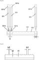
- Figure 2 schematically shows a squeegee rubber 1 according to the invention, which is received in engagement devices 303 of the bolts 301. From the illustration it is clear how the engagement devices 303 are received in the recesses 101 of the squeegee rubber 1, while the grooves 103 remain free in between.
- Figure 3a the view of the Figure 2 shown again in a schematic side view, while the detailed representation of the Figure 3b the arrangement and dimensions of the recesses 101 (length b1, depth t1) and the grooves 103 (length b2, depth t2).
- the width b3 of the engagement device 303 is greater than the length b1 of the recesses 101 in order to ensure a secure hold.
- the concave formation 301k of the bolt 301 is also highlighted.
- a bolt 301 according to the invention is Figure 4 shown schematically at different angles. Important here are the concave formations 301k, which have a direct influence on the width of the support surface 301f for the squeegee rubber 1 in the engagement device 303.
- the width of the support surface 301f is reduced by at least 50% compared to the width of the bolt 301. This smaller support surface 301f significantly increases the flexibility of the squeegee rubber 1, while the design of the squeegee rubber 1 itself, as described above, in conjunction with the engagement device 303, ensures that the squeegee rubber 1 is held in place optimally.
- a fully assembled doctor head 3 according to an embodiment of the invention is shown in a perspective view in Figure 5
- the doctor head 3 according to the invention initially has a base body 305 with a Element 309 and at least one bolt guide 307 for at least one bolt 301, which has an engagement device 303 at its first end 301a for receiving the squeegee rubber 1 described above.
- Each bolt guide 307 receives the shaft 301s of a bolt 301 and guides it.
- the squeegee head 3 has four bolts 301.
- the number of bolts 301 is not limited to one centimeter of the length of the squeegee rubber 1.
- a practical difficulty, however, is that the spring pressure above each bolt 301 is individually adjustable and each device 313 must be able to be secured. This becomes more difficult the more bolts 301 are close together.
- an element 309 is provided for receiving at least one spring 311, which generates a contact pressure of the at least one bolt 301.
- the element 309 is arranged above the bolt guide 307 in the base body 305.
- the spring 311 is operatively connected to the second end 301b of the bolt 301, i.e. it presses on the bolt 301 from above.
- At least the element 309 is designed symmetrically in this embodiment, and in the present illustration the entire base body 305 is also symmetrical.
- This symmetry relates in particular to the two opposing projections for fastening in/on the printing device. As already described above, this enables the doctor head 3 to be rotated easily and quickly by 180 degrees and thus the printing direction to be reversed easily and quickly.
- a device 313 is provided for generating this pre-tension, which is accommodated in a two-part clamping system 315a, 315b.
- the two-part clamping system has a clamping strip 315b by means of which the device 313 can be reversibly secured. In this way, the device 313 cannot be accidentally adjusted during operation.
- the base body 305 has at least two bolt guides 307a, 307b arranged one above the other, which are separated by a spacer block 317. As already explained above, this arrangement serves for the lubrication-free storage of the bolts 301.
- Each bolt guide 307a, 307b receives the shaft 301s of a bolt 301 and guides it. At least the bolts 301 and the bolt guide 307 are made of hardened steel.
- Figure 6 shows the squeegee head of the Figure 5 once again from the side, whereby it is particularly clear how the terminal block 315b rests against the device 313 in order to secure it reversibly.
- FIG. 7 Four bolts 301 with springs 311 and devices 313 arranged above them are shown, as they are inside the doctor head 3 from the Figures 4 and 5 are arranged. To clarify the individual elements, only one spring 311 is shown here.
- the individual bolts 301 have a locking element 319 at their upper end, which is only indicated here.
- the locking element 319 prevents the bolt 301 from slipping downwards out of the bolt guide 307a, 307b.
- the guides within the base body 305 are wide enough that the locking elements 319 can slide safely in them.
- FIG 8a shows the doctor head 3 described above schematically from above, in particular the two-part clamping system 315a, 315b.
- S2 indicates screws (cylinder head with hexagon socket M4x50), which in this embodiment are accommodated in the element 309.
- the other two openings AS1 serve to accommodate the screws S1, which are not shown here.
- Figure 8a shows a section line B - B, whose intersection in Figure 8b is shown.
- the screw S2 leads through the element 309 into the lower bolt guide 307b, in which an M4 thread is provided for screwing in.
- This design offers the possibility of loosening the two screws S2 and removing the unit consisting of bolt guides 307a, 307b, spacer block 317 and bolt 301 accommodated therein and reinserting it rotated by 180°. This makes it easy to reverse the squeegee direction, which is indicated in the figure with an arrow.
- the present invention makes it even easier to change the printing direction.
- the machine setter will opposite projection for fastening the squeegee head 3 to change the printing direction.
- the Figure 9 is a schematic exploded view of the two-part clamping system 315a, 315b, whereby this embodiment has two clamping strips 315b which are screwed onto the symmetrically designed element 315a.
- 315a1 denotes the threads for receiving the devices 313, while 315a2 indicates the thread for securing the clamping strip 315b.
- 315a2 shows a thread into which the screw 315a3 is screwed. This serves to attach the respective clamping strip 315b to the element 315a of the two-part clamping system 315a, 315b.
- the terminal block 315b is shown in perspective in the exploded view, from which the flexible lip 315g, here in the form of a rubber lip, emerges, which rests against the devices 313 during fastening.
- the element 315a is attached to the element 309 using the screws S1.
- the heads of the screws S2, see also Figure 8a are predominantly located in element 309.
- the screws S2 also serve to connect the bolt guides 307a, 307b and the spacer block 317 to the element 309.
- the tops of the heads of the screws S2 also serve to center the element 315a.
Landscapes
- Engineering & Computer Science (AREA)
- Mechanical Engineering (AREA)
- Screen Printers (AREA)
Applications Claiming Priority (1)
| Application Number | Priority Date | Filing Date | Title |
|---|---|---|---|
| DE102023121619.8A DE102023121619A1 (de) | 2023-08-11 | 2023-08-11 | Rakelgummi, Rakelkopf und Rakelsystem |
Publications (1)
| Publication Number | Publication Date |
|---|---|
| EP4506168A1 true EP4506168A1 (fr) | 2025-02-12 |
Family
ID=92302399
Family Applications (1)
| Application Number | Title | Priority Date | Filing Date |
|---|---|---|---|
| EP24020263.0A Pending EP4506168A1 (fr) | 2023-08-11 | 2024-08-09 | Caoutchouc racleur, tête de racle et système de racle |
Country Status (2)
| Country | Link |
|---|---|
| EP (1) | EP4506168A1 (fr) |
| DE (1) | DE102023121619A1 (fr) |
Citations (6)
| Publication number | Priority date | Publication date | Assignee | Title |
|---|---|---|---|---|
| EP0099587B1 (fr) | 1982-07-23 | 1987-08-12 | Rebhan, Horst | Racle pour imprimer des objets par sérigraphie |
| DE20303186U1 (de) | 2003-02-27 | 2003-04-30 | Gst Dekoracni Zarizeni A Strojni Tecnika S.R.O., Hranice | Rakelkopf zum Bedrucken von Körpern im Siebdruckverfahren |
| US20030226579A1 (en) * | 2002-06-06 | 2003-12-11 | Carrier Gordon Eugene | Serrated doctor blades |
| US6921064B2 (en) * | 2003-12-22 | 2005-07-26 | Xerox Corporation | Metering blade suspension system |
| CN208148768U (zh) * | 2018-03-26 | 2018-11-27 | 南京中印防伪科技有限公司 | 一种丝网印刷机的刮墨装置 |
| WO2021233591A1 (fr) | 2020-05-19 | 2021-11-25 | Daetwyler Swisstec Ag | Bande de racles pour coupe à longueur pour une utilisation en impression |
Family Cites Families (3)
| Publication number | Priority date | Publication date | Assignee | Title |
|---|---|---|---|---|
| DE9003485U1 (de) * | 1990-03-24 | 1991-04-04 | Messerschmitt, Elmar, Dr., 8000 München | Rakellippe bei einer Beschichtungsrakel zur Beschichtung eines Drucksiebes |
| DE9103571U1 (de) * | 1991-03-21 | 1992-07-23 | Zimmer, Johannes, Klagenfurt, Kärnten | Rakelgerät |
| DE20303187U1 (de) * | 2003-02-27 | 2003-04-30 | Gst Dekoracni Zarizeni A Strojni Tecnika S.R.O., Hranice | Rakelkopf zum Bedrucken von Körpern im Siebdruckverfahren |
-
2023
- 2023-08-11 DE DE102023121619.8A patent/DE102023121619A1/de active Pending
-
2024
- 2024-08-09 EP EP24020263.0A patent/EP4506168A1/fr active Pending
Patent Citations (6)
| Publication number | Priority date | Publication date | Assignee | Title |
|---|---|---|---|---|
| EP0099587B1 (fr) | 1982-07-23 | 1987-08-12 | Rebhan, Horst | Racle pour imprimer des objets par sérigraphie |
| US20030226579A1 (en) * | 2002-06-06 | 2003-12-11 | Carrier Gordon Eugene | Serrated doctor blades |
| DE20303186U1 (de) | 2003-02-27 | 2003-04-30 | Gst Dekoracni Zarizeni A Strojni Tecnika S.R.O., Hranice | Rakelkopf zum Bedrucken von Körpern im Siebdruckverfahren |
| US6921064B2 (en) * | 2003-12-22 | 2005-07-26 | Xerox Corporation | Metering blade suspension system |
| CN208148768U (zh) * | 2018-03-26 | 2018-11-27 | 南京中印防伪科技有限公司 | 一种丝网印刷机的刮墨装置 |
| WO2021233591A1 (fr) | 2020-05-19 | 2021-11-25 | Daetwyler Swisstec Ag | Bande de racles pour coupe à longueur pour une utilisation en impression |
Also Published As
| Publication number | Publication date |
|---|---|
| DE102023121619A1 (de) | 2025-02-13 |
Similar Documents
| Publication | Publication Date | Title |
|---|---|---|
| EP0595074B1 (fr) | Dispositif de serrage | |
| DE69727306T2 (de) | Modulare stanzteilübertragungseinrichtung | |
| EP0403427A2 (fr) | Dispositif d'abloquage pour pièces devant être usinées sur une machine-outil | |
| DE3617581C2 (fr) | ||
| EP1711288A1 (fr) | Dispositif d'assemblage | |
| DE3151275A1 (de) | Befestigungsvorrichtung fuer werkzeuge | |
| EP0892883A1 (fr) | Dispositif de per age | |
| DE2164093B2 (de) | Schneidwerkzeug | |
| CH711906A2 (de) | Vorrichtung zum Spannen mehrerer Werkstücke auf einem Teilapparat einer Werkzeugmaschine. | |
| DE10212343A1 (de) | Schlittensystem | |
| EP4506168A1 (fr) | Caoutchouc racleur, tête de racle et système de racle | |
| DE9315178U1 (de) | Linearführung | |
| DE69703634T2 (de) | Messeranordnung für Rotationsschneidvorrichtung | |
| EP3689545B1 (fr) | Mâchoire de serrage permettant de serrer une pièce | |
| DE2542346B2 (de) | Innenraeumwerkzeug, insbesondere zur herstellung von profilnuten | |
| EP2394790B1 (fr) | Mors de rechange pour un étau | |
| DE2544877A1 (de) | Werkzeughalter | |
| EP4349530B1 (fr) | Dispositif de fixation pour une pièce à usiner | |
| DE10311911B4 (de) | Schnellwechselvorrichtung für Stanz,- Schneid- oder Lochstempel | |
| EP1457297A2 (fr) | Dispositif de gaufrage et/ou de découpe d'une pièce | |
| DE102022125476A1 (de) | Befestigungsvorrichtung für ein Werkstück | |
| DE8903929U1 (de) | Vorrichtung zum Spannen von Werkstücken | |
| DE202005009746U1 (de) | Spanneinrichtung | |
| DE102022125475A1 (de) | Wasserstrahlschneideverfahren | |
| CH698237B1 (de) | Schablone zum Anreissen und Übertragen von Massen und zum Positionieren von Werkzeugen auf Oberflächen von Bauteilen. |
Legal Events
| Date | Code | Title | Description |
|---|---|---|---|
| PUAI | Public reference made under article 153(3) epc to a published international application that has entered the european phase |
Free format text: ORIGINAL CODE: 0009012 |
|
| STAA | Information on the status of an ep patent application or granted ep patent |
Free format text: STATUS: THE APPLICATION HAS BEEN PUBLISHED |
|
| AK | Designated contracting states |
Kind code of ref document: A1 Designated state(s): AL AT BE BG CH CY CZ DE DK EE ES FI FR GB GR HR HU IE IS IT LI LT LU LV MC ME MK MT NL NO PL PT RO RS SE SI SK SM TR |
|
| STAA | Information on the status of an ep patent application or granted ep patent |
Free format text: STATUS: REQUEST FOR EXAMINATION WAS MADE |
|
| 17P | Request for examination filed |
Effective date: 20250505 |
|
| STAA | Information on the status of an ep patent application or granted ep patent |
Free format text: STATUS: EXAMINATION IS IN PROGRESS |
|
| 17Q | First examination report despatched |
Effective date: 20250613 |