EP4506272A1 - Mit einem fliessfähigen produkt gefüllte verpackung und verfahren zur herstellung einer verpackung - Google Patents
Mit einem fliessfähigen produkt gefüllte verpackung und verfahren zur herstellung einer verpackung Download PDFInfo
- Publication number
- EP4506272A1 EP4506272A1 EP24192232.7A EP24192232A EP4506272A1 EP 4506272 A1 EP4506272 A1 EP 4506272A1 EP 24192232 A EP24192232 A EP 24192232A EP 4506272 A1 EP4506272 A1 EP 4506272A1
- Authority
- EP
- European Patent Office
- Prior art keywords
- package
- weakening
- weakening line
- wall
- side wall
- Prior art date
- Legal status (The legal status is an assumption and is not a legal conclusion. Google has not performed a legal analysis and makes no representation as to the accuracy of the status listed.)
- Pending
Links
Images



Classifications
-
- B—PERFORMING OPERATIONS; TRANSPORTING
- B65—CONVEYING; PACKING; STORING; HANDLING THIN OR FILAMENTARY MATERIAL
- B65D—CONTAINERS FOR STORAGE OR TRANSPORT OF ARTICLES OR MATERIALS, e.g. BAGS, BARRELS, BOTTLES, BOXES, CANS, CARTONS, CRATES, DRUMS, JARS, TANKS, HOPPERS, FORWARDING CONTAINERS; ACCESSORIES, CLOSURES, OR FITTINGS THEREFOR; PACKAGING ELEMENTS; PACKAGES
- B65D5/00—Rigid or semi-rigid containers of polygonal cross-section, e.g. boxes, cartons or trays, formed by folding or erecting one or more blanks made of paper
- B65D5/02—Rigid or semi-rigid containers of polygonal cross-section, e.g. boxes, cartons or trays, formed by folding or erecting one or more blanks made of paper by folding or erecting a single blank to form a tubular body with or without subsequent folding operations, or the addition of separate elements, to close the ends of the body
- B65D5/029—Rigid or semi-rigid containers of polygonal cross-section, e.g. boxes, cartons or trays, formed by folding or erecting one or more blanks made of paper by folding or erecting a single blank to form a tubular body with or without subsequent folding operations, or the addition of separate elements, to close the ends of the body the tubular body presenting a special shape
-
- B—PERFORMING OPERATIONS; TRANSPORTING
- B65—CONVEYING; PACKING; STORING; HANDLING THIN OR FILAMENTARY MATERIAL
- B65D—CONTAINERS FOR STORAGE OR TRANSPORT OF ARTICLES OR MATERIALS, e.g. BAGS, BARRELS, BOTTLES, BOXES, CANS, CARTONS, CRATES, DRUMS, JARS, TANKS, HOPPERS, FORWARDING CONTAINERS; ACCESSORIES, CLOSURES, OR FITTINGS THEREFOR; PACKAGING ELEMENTS; PACKAGES
- B65D5/00—Rigid or semi-rigid containers of polygonal cross-section, e.g. boxes, cartons or trays, formed by folding or erecting one or more blanks made of paper
- B65D5/02—Rigid or semi-rigid containers of polygonal cross-section, e.g. boxes, cartons or trays, formed by folding or erecting one or more blanks made of paper by folding or erecting a single blank to form a tubular body with or without subsequent folding operations, or the addition of separate elements, to close the ends of the body
- B65D5/06—Rigid or semi-rigid containers of polygonal cross-section, e.g. boxes, cartons or trays, formed by folding or erecting one or more blanks made of paper by folding or erecting a single blank to form a tubular body with or without subsequent folding operations, or the addition of separate elements, to close the ends of the body with end-closing or contents-supporting elements formed by folding inwardly a wall extending from, and continuously around, an end of the tubular body
- B65D5/064—Rectangular containers having a body with gusset-flaps folded outwardly or adhered to the side or the top of the container
-
- B—PERFORMING OPERATIONS; TRANSPORTING
- B65—CONVEYING; PACKING; STORING; HANDLING THIN OR FILAMENTARY MATERIAL
- B65D—CONTAINERS FOR STORAGE OR TRANSPORT OF ARTICLES OR MATERIALS, e.g. BAGS, BARRELS, BOTTLES, BOXES, CANS, CARTONS, CRATES, DRUMS, JARS, TANKS, HOPPERS, FORWARDING CONTAINERS; ACCESSORIES, CLOSURES, OR FITTINGS THEREFOR; PACKAGING ELEMENTS; PACKAGES
- B65D5/00—Rigid or semi-rigid containers of polygonal cross-section, e.g. boxes, cartons or trays, formed by folding or erecting one or more blanks made of paper
- B65D5/02—Rigid or semi-rigid containers of polygonal cross-section, e.g. boxes, cartons or trays, formed by folding or erecting one or more blanks made of paper by folding or erecting a single blank to form a tubular body with or without subsequent folding operations, or the addition of separate elements, to close the ends of the body
- B65D5/06—Rigid or semi-rigid containers of polygonal cross-section, e.g. boxes, cartons or trays, formed by folding or erecting one or more blanks made of paper by folding or erecting a single blank to form a tubular body with or without subsequent folding operations, or the addition of separate elements, to close the ends of the body with end-closing or contents-supporting elements formed by folding inwardly a wall extending from, and continuously around, an end of the tubular body
- B65D5/064—Rectangular containers having a body with gusset-flaps folded outwardly or adhered to the side or the top of the container
- B65D5/065—Rectangular containers having a body with gusset-flaps folded outwardly or adhered to the side or the top of the container with supplemental means facilitating the opening, e.g. tear lines, tear tabs
-
- B—PERFORMING OPERATIONS; TRANSPORTING
- B65—CONVEYING; PACKING; STORING; HANDLING THIN OR FILAMENTARY MATERIAL
- B65D—CONTAINERS FOR STORAGE OR TRANSPORT OF ARTICLES OR MATERIALS, e.g. BAGS, BARRELS, BOTTLES, BOXES, CANS, CARTONS, CRATES, DRUMS, JARS, TANKS, HOPPERS, FORWARDING CONTAINERS; ACCESSORIES, CLOSURES, OR FITTINGS THEREFOR; PACKAGING ELEMENTS; PACKAGES
- B65D5/00—Rigid or semi-rigid containers of polygonal cross-section, e.g. boxes, cartons or trays, formed by folding or erecting one or more blanks made of paper
- B65D5/42—Details of containers or of foldable or erectable container blanks
- B65D5/72—Contents-dispensing means
- B65D5/74—Spouts
- B65D5/746—Spouts formed separately from the container
- B65D5/747—Spouts formed separately from the container with means for piercing or cutting the container wall or a membrane connected to said wall
Definitions
- the present invention relates to a package filled with a pourable product, in particular a pourable food product.
- the present invention also relates to a method for forming a package.
- liquid or pourable food products such as fruit juice, UHT (ultra-high-temperature treated) milk, wine, tomato sauce, etc.
- UHT ultra-high-temperature treated milk
- wine tomato sauce
- etc. are sold in packages made of sterilized packaging material.
- a typical example is the parallelepiped-shaped package for liquid or pourable food products known as Tetra Brik Aseptic (registered trademark), which is made by sealing and folding a laminated packaging blank.
- the packaging blank has a multilayer structure comprising a fibrous base layer, e.g. of paper or cardboard, covered on both sides with layers of heat-seal plastic material, e.g. polyethylene.
- the packaging blank also comprises a layer of oxygen-barrier material (an oxygen-barrier layer), e.g. an aluminum foil, which is superimposed on a layer of heat-seal plastic material, and is in turn covered with another layer of heat-seal plastic material forming the inner face of the package eventually contacting the food product.
- Packages of this sort are normally produced on fully automatic packaging apparatuses, which form the packages from respective packaging blanks.
- These packaging blanks can be provided in the form of single packaging blanks or in the form of a web, which is formed from a plurality of successively arranged packaging blanks.
- the packaging apparatus In the case of the packaging apparatus being designed to form the packages from a web, the packaging apparatus advances and sterilizes the web, which is then formed into a tube and filled with the pourable product before the tube is formed into individual sealed packages.
- the packaging blanks are provided with a plurality of crease lines.
- a typical package has a side wall that comprises main panels, for example a front panel, a back panel opposite to the front panel and lateral panels interposed between the front panel and the back panel.
- the side wall may also comprise corner panels.
- the user When a user grips the package, the user typically is in contact with one or more corner panels of the side wall and with one or more main panels of the side wall.
- Number 1 in Figure 1 indicates a package filled with a pourable product, preferentially a pourable food product, such as pasteurized milk, milk, milk-products, drinking yoghurt, yoghurt-drinks, beverages, fruit juice, wine, tomato sauce, salt, sugar, etc.
- a pourable food product such as pasteurized milk, milk, milk-products, drinking yoghurt, yoghurt-drinks, beverages, fruit juice, wine, tomato sauce, salt, sugar, etc.
- package 1 may be formed from a packaging blank 2 as e.g. shown in Figure 2 .
- each package 1 is formed from one respective packaging blank 2 by means of an automatic packaging machine.
- the automatic packaging machine may be configured to form packages 1 from the respective packaging blanks 2 and to fill packages 1 with the pourable product.
- packaging blanks 2 may have a multilayer structure.
- each packaging blank 2 may comprise at least a layer of fibrous material, such as e.g. a paper or cardboard layer, and at least two layers of heat-seal plastic material, e.g. polyethylene, interposing the layer of fibrous material in between one another.
- fibrous material such as e.g. a paper or cardboard layer
- heat-seal plastic material e.g. polyethylene
- One of these two layers of heat-seal plastic material may define an inner face of the respective package 1 formed from the respective packaging blank 2 and eventually contacting the pourable product.
- each packaging blank 2 may also comprise a layer of gas- and light-barrier material, e.g. aluminum foil or ethylene vinyl alcohol (EVOH) film, in particular being arranged between one of the layers of the heat-seal plastic material and the layer of fibrous material.
- gas- and light-barrier material e.g. aluminum foil or ethylene vinyl alcohol (EVOH) film
- EVOH ethylene vinyl alcohol
- packaging blank 2 may also comprise a further layer of heat-seal plastic material being interposed between the layer of gas- and light-barrier material and the layer of fibrous material.
- packaging blanks 2 may be provided in the form of a web.
- the web may be formed from a plurality of successively arranged packaging blanks 2.
- each repeat unit i.e. the respective packaging blank 2 forms the precursor of one respective package 1.
- the packaging machine may be configured to produce packages 1 from the web such that each package 1 results from one respective packaging blank 2.
- each packaging blank 2 may comprise a desired pattern/decoration.
- package 1 may extend along a longitudinal axis A, preferentially also along a first transversal axis B perpendicular to longitudinal axis A and a second transversal axis C perpendicular to longitudinal axis A and first transversal axis B.
- an extension of package 1 along longitudinal axis A may be larger than a respective extensions of package 1 along first transversal axis B and second transversal axis C.
- package 1 may comprise a bottom wall 3 and a top wall 4 spaced apart from one another along longitudinal axis A. Additionally, package 1 comprises a side wall 5 interposed between (and connected to) bottom wall 3 and top wall 4.
- bottom wall 3 may be defined as the wall of package 1 that has a substantially planar shape and that is substantially perpendicular to longitudinal axis A. According to some possible non-limiting embodiments, bottom wall 3 may be configured to be placed on a support surface, such as a support surface of a shelf, a fridge, a table, a working plane or the like.
- bottom wall 3 With package 1 being placed on the support surface (and in its nominal position, i.e. when being used by a user in an intended manner), bottom wall 3 is in contact with the support surface and top wall 4 is distanced from the support surface.
- side wall 5 may be the portion of package 1 that is gripped by a user during an outpouring action of the pourable product from package 1.
- top wall 4 may be configured to be manipulated such to allow for the outpouring of the pourable product.
- top wall 4 may be manipulated so as to obtain a pouring opening.
- top wall 4 may be parallel to bottom wall 3.
- package 1 may comprise a longitudinal seam portion 6, e.g. resulting from forming packages 1 from a tube filled with the pourable product, the tube presenting a longitudinal seal.
- longitudinal seam portion 6 may be substantially parallel to longitudinal axis A.
- each package 1 may comprise a first transversal seal portion and a second transversal seal portion 7, preferentially being transversal to longitudinal axis A.
- first transversal seal portion may be comprised by and/or associated to bottom wall 3 and second transversal seal portion 7 may be comprised by and/or associated to top wall 4.
- side wall 5 may comprise a plurality of main panels, more specifically a front panel 8, a back panel 9 opposite to front panel 8 and a plurality of, in the example shown two, lateral panels 10, each one interposed between back panel 9 and front panel 8.
- side wall 5 may also comprise a plurality of corner panels 11, each one being interposed between one respective main panel.
- each corner panel 11 may be interposed between one respective lateral panel 10 and one of front panel 8 and back panel 9.
- each main panel of side wall 5 may be interposed between two respective corner panels 11.
- a hand of a user may contact at least partially back panel 9, lateral panels 10 and one or more corner panels 11.
- back panel 9 may comprise longitudinal seam portion 6.
- top wall 4 may comprise a plurality of top edges 12 and bottom wall 3 may comprise a plurality of bottom edges 13.
- each one of front panel 8, back panel 9 and lateral panels 10 may extend from one respective top edge 12 to one respective bottom edge 13.
- top wall 4 and bottom wall 3 may comprise a plurality of, respectively, top intersection edges 14 and bottom intersection edge 15. At each top intersection edge 14 two respective top edges 12 intersect and/or contact one another and at each bottom intersection edge 15 two respective bottom edges 12 intersect and/or contact one another.
- each corner panel 11 may extend between one top intersection edge 14 and one bottom intersection edge 15.
- package 1 may comprise flaps 16 attached to and/or extending from top wall 4.
- side wall 5 comprises a plurality of weakening lines 20 and a plurality of weakening lines 21, weakening lines 20 defining a first group and weakening lines 21 defining a second group.
- side wall 5 is folded along weakening lines 20 of the first group, side wall 5 is not folded along weakening lines 21 of the second group.
- side wall 5 is not folded and has not undergone any step of folding along weakening lines 21 prior, during and after the formation of package 1.
- weakening lines 20 may have a function in defining the overall shape of package 1, weakening lines 21 may allow to improve the gripping of package 1.
- weakening lines 21 may allow to improve the tactile experience of a user when gripping package 1.
- Weakening lines 20 and weakening lines 21 may be characterized by a material displacement, i.e. mechanical (permanent) deformation, of the multilayer packaging material, e.g. obtained during an embossing of the multilayer packaging material for defining weakening lines 20 and weakening lines 21.
- weakening lines 21 may protrude from side wall 5 towards the outside of package 1 or may protrude from side wall 5 towards the inside of package 1.
- all weakening lines 21 may protrude from side wall 5 towards the outside of package 1 or all weakening lines 21 may protrude from side wall 5 towards the inside of package 1 or some weakening lines 21 may protrude from side wall 5 towards the outside of package 1 and other weakening lines 21 may protrude from side wall 5 towards the inside of package 1.
- weakening lines 20 and/or weakening lines 21 may be obtained by embossing or the like of the multilayer packaging material.
- weakening lines 20 and/or weakening lines 21 may be transversal to longitudinal axis A and/or top edge 12 and/or bottom edge 13.
- first weakening lines 20 and second weakening lines 21 may be non-parallel to longitudinal axis A.
- both weakening lines 20 and second weakening lines 21 may be inclined (in particular not perpendicular) with respect to top edge 12 and/or bottom edge 13.
- back panel 9 may be void of any weakening lines 21.
- each corner panel 11 may be delimited by a plurality of weakening lines 20, i.e. each corner panel 11 is defined by weakening lines 20 along which side wall 5 has been folded.
- each main panel (i.e. front panel 8, back panel 9 and lateral panels 10) of side wall 5 may be delimited by a plurality of weakening lines 20. More specifically, each main panel of side wall 5 may be interposed between and/or delimited by one or more weakening lines 20 of one corner panel 11 and one or more weakening lines 20 of another corner panel 11.
- each corner panel 11 may be delimited by four weakening lines 20.
- each main panel of side wall 5 may be delimited by two weakening lines 20 of one corner panel 11 and two weakening lines 20 of another corner panel 11.
- no weakening lines 21 may be present on corner panels 11, i.e. corner panels 11 are free of any weakening line 21.
- one or more corner panels 11 may comprise weakening lines 21.
- each weakening line 20 may extend from one or more respective top edges 14 or from one or more respective bottom intersection edges 15, for example towards a center portion 22 of side wall 5, more specifically of one respective main panel (for example front panel 8, back panel 9 or one of the lateral panels 10).
- center portion 22 of side wall 5 may be centered with respect to the extension of package 1 along longitudinal axis A.
- each weakening line 20 may extend from one respective top intersection edge 14 or from one respective bottom intersection edge 15, for example towards center portion 22 of side wall 5, more specifically of one respective main panel (for example front panel 8, back panel 9 or one of the lateral panels 10).
- each weakening line 20 may comprise a first end 23 and a second end 24 opposite to first end 23.
- each first end 23 may be interposed between two respective main panels and each second end 24 may be arranged on one respective center portion 22 of side wall 5, more specifically of one respective main panel.
- a weakening line 20 extending from one respective top intersection edge 14 and another weakening line 20 extending from one respective bottom intersection edge 15 may extend up to the same second end 24, i.e. share the same second end 24.
- each first end 23 may be in contact with one respective top intersection edge 14 or one respective bottom intersection edge 15.
- each weakening line 21 may be arranged on and/or included within one respective main panel (for example on front panel 8 or one of lateral panels 10) and/or may be interposed between two respective corner panels 11.
- each weakening line 21 may extend from one or more respective top edges 12 or one or more respective bottom edges 13.
- each weakening line 21 may contact and/or extend from one respective top intersection edge 14 or one respective bottom intersection edge 15.
- each weakening line 21 may extend to an intersection point of two respective weakening lines 20 (i.e. second end 24 shared by two respective weakening lines 20).
- each weakening line 21 may extend from a first weakening line 20 partially delimiting a first corner panel 11 to one or more second weakening lines 20 partially delimiting a second corner panel 11 different from the first corner panel 11.
- each weakening line 21 may be a continuation of a respective weakening line 20.
- each weakening line 21 may intersect with and/or may contact at least one weakening line 20.
- each weakening line 21 may contact four weakening lines 20. Two of these weakening lines 20 partially delimit one respective corner panel 11 and the other two weaking line 20 partially delimits another corner panel 11.
- each weakening line 21 may intersect with and/or contact at least one other weakening line 21.
- each weakening lines 21 and each weakening line 20, when being projected onto a plane, have a curved shape.
- Packaging blank 2 of Figure 2 is designed to allow formation of package 1.
- each packaging blank 2 may comprise:
- transversal axis F may be perpendicular to longitudinal axis E.
- each longitudinal axis E may intersect the respective transversal axis F at a centre point of packaging blank 2.
- each packaging blank 2 may extend within a plane spanned by longitudinal axis E and transversal axis F.
- each packaging blank 2 may have a (substantially) bi-dimensional shape, i.e. respective extensions of each packaging blank 2 along longitudinal axis E and transversal axis F may be (significantly) larger than a thickness of packaging blank 2.
- the thickness of packaging blank 2 may be negligible in comparison to the respective extensions of packaging blank 2 along longitudinal axis E and transversal axis F.
- each packaging blank 2 may have a rectangular or square shape.
- first direction D1 may be parallel to transversal axis F.
- second direction D2 may be parallel to longitudinal axis E.
- each first longitudinal boundary edge 26 and each second longitudinal boundary edge 27 may be connected to and interposed between the respective first transversal boundary edge 28 and the respective second transversal boundary edge 29.
- each first longitudinal boundary edge 26 and each second longitudinal boundary edge 27 may be arranged at an angle of about 90° with respect to the respective first transversal boundary edge 28 and the respective second transversal boundary edge 29.
- each packaging blank 2 being arranged singularly, i.e. separated from the other packaging blanks 2, the respective first longitudinal boundary edge 26, the respective second longitudinal boundary edge 27, the respective first transversal boundary edge 28 and the respective second transversal boundary edge 29 may be real edges.
- each first transversal boundary edge 28 of one packaging blank 2 may be adjacent to, or coincide with, the respective second transversal boundary edge 29 of another packaging blank 2.
- each first longitudinal boundary edge 26 of one packaging blank 2 may be adjacent to, or coincide with, the respective second longitudinal boundary edge 27 of another packaging blank 2.
- each packaging blank 2 may comprise a top section having a top crease pattern 30 configured to define the shape of at least top wall 4.
- top crease pattern 30 may be configured to define top wall 4 and flaps 16.
- packaging blank 2 may also comprise a bottom section having a bottom crease pattern 31 configured to define the shape of at least bottom wall 3.
- bottom crease pattern 31 may be configured to define bottom wall 3 and flaps (not shown) attached to bottom wall 3.
- packaging blank 2 also comprises an intermediate section having an intermediate weakening line pattern 32 interposed between top crease pattern 30 and bottom crease pattern 31 and being configured to define side wall 5.
- intermediate weakening line pattern 32 may define front panel 8, back panel 9, lateral panels 10 and corner panels 11.
- top crease pattern 30, bottom crease pattern 31 and intermediate weakening line pattern 32 may define respective sections of top wall 4, bottom wall 3 and side wall 5.
- top crease pattern 30, bottom crease pattern 31 and intermediate weakening line pattern 32 may define respective sections of top wall 4, bottom wall 3 and side wall 5.
- intermediate weakening line pattern 32 may comprise weakening lines 20 and weakening lines 21.
- side wall 5 is configured to be folded along weakening lines 20 during the formation of package 1 and side wall 5 is configured not to be folded along weakening lines 21 during the formation of package 1.
- each top crease pattern 30 comprises at least a first transversal crease line 33 extending transversally to longitudinal axis E.
- bottom crease pattern 31 may comprises at least a second transversal crease line 34 extending transversally to longitudinal axis E.
- first transversal crease line 33 and second transversal crease line 34 are displaced from one another along second direction D2.
- first transversal crease line 33 and second transversal crease line 34 delimit together the intermediate section.
- top crease pattern 30 may comprise a third transversal crease line 35 displaced from first transversal crease line 33 along second direction D2 and interposed between first transversal boundary edge 28 and first transversal crease line 33 along second direction D2.
- bottom crease pattern 31 may comprise a fourth transversal crease line 36 displaced from second transversal crease line 34 along second direction D2 and interposed between second transversal boundary edge 29 and second transversal crease line 34 along second direction D2.
- first transversal crease line 33 and second transversal crease line 34 may have rectilinear shapes.
- third transversal crease line 35 and/or fourth transversal crease line 36 may have rectilinear shapes.
- each weakening line 20 and each weakening line 21 may contact at least one of first transversal crease line 33 and second transversal crease line 34.
- top crease pattern 30 and bottom crease pattern 31 may comprise further crease lines 37 intended to define the shape of top wall 4 or bottom wall 3 and/or flaps 16 of top wall 4 and the flaps of bottom wall 3.
- the method for forming package 1 comprises the steps of:
- number 1' indicates an alternative embodiment of a package according to the present invention; as package 1' is similar to package 1, the following description is limited to the differences between them, and using the same references, where possible, for identical or corresponding parts.
- Package 1' differs from package 1 in comprising an opening 45, preferentially covered with a separation membrane. More specifically, the separation membrane may be defined by a portion of the multilayer packaging material.
- opening 45 may be configured to receive a straw and/or to allow for the introduction of a straw into package 1. Additionally, the separation membrane may be rupturable upon the application of a force onto the separation membrane by means of a straw.
- each opening 45 may be arranged on top wall 4.
- each opening 45 may be delimited by a rim 46.
- Rim 46 may have a circular shape.
- the respective packaging blank used to form package 1' may be based on packaging blank 2 and may additionally have an opening (e.g. covered with the separation membrane), in particular arranged on the top section of packaging blank 2.
- the method for forming package 1' is similar to the method for forming package 1 and we refer to the description provided with regard to the formation of package 1.
- number 1" indicates an alternative embodiment of a package according to the present invention; as package 1" is similar to package 1, the following description is limited to the differences between them, and using the same references, where possible, for identical or corresponding parts.
- package 1'' comes along with a slanted top wall 4.
- Package 1" differs from package 1 in that the respective top wall 4 of package 1'' is inclined with respect to bottom wall 3 and/or longitudinal axis A.
- Packaging blank 2" shown in Figure 7 allows to form package 1''.
- Packaging blank 2 is similar to packaging blank 2, the following description is limited to the differences between them, and using the same references, where possible, for identical or corresponding parts.
- Packaging blank 2" differs from packaging blank 2 in that first transversal crease line 33 is not rectilinear, but comprises a plurality of first rectilinear sections 47 being parallel to one another and to first longitudinal boundary edge 26 and second longitudinal boundary edge 27, and second rectilinear sections 48 being inclined with respect to first rectilinear sections 47.
- each second rectilinear section 48 may be interposed between two first rectilinear sections 47.
- the method for forming package 1" is similar to the method for forming package 1 and we refer to the description provided with regard to the formation of package 1.
- numbers 1′′′ and 1′′′ indicate two alternative embodiments of a package according to the present invention; as packages 1′′′ and 1′′′ are similar to package 1'', the following description is limited to the differences between them, and using the same references, where possible, for identical or corresponding parts.
- packages 1′′′ and 1 ⁇ may be provided with an opening device. Therefore, packages 1′′′ and 1 ⁇ may comprise respective openings 49 and the respective opening devices may be arranged on packages 1′′′ and 1 ⁇ about the respective openings 49.
- opening 49 may be covered with a separation membrane configured to be ruptured upon a first time opening and/or manipulation of the opening device.
- opening 49 of package 1′′′ is arranged on top wall 4 only, while opening 49 of packages 2 ⁇ is partially arranged on top wall 4 and partially arranged on front wall 8.
- respective packaging blanks used to form packages 1''' and 1′′′ may be based on packaging blank 2" and may additionally have a respective opening, which gives rise to the respective openings 49.
- the method for forming packages 1′′′ and 1 ⁇ is similar to the method for forming package 1 and we refer to the description provided with regard to the formation of package 1.
- number 1′′′ ⁇ indicates an alternative embodiment of a package according to the present invention.
- package 1′′′ ⁇ ' is similar to package 1, the following description is limited to the differences between them, and using the same references, where possible, for identical or corresponding parts.
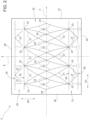
- package 1′′′ ⁇ ' differs from package 1 in the shape of weakening lines 20 and of weakening lines 21.
- weakening lines 20 and weakening lines 21 when being projected onto a projection plane have a linear shape.
- package 1′′′ ⁇ differs from package 1 in that weakening lines 21 do not intersect with and/or contact any top edge 12 or any bottom edge 13.
- weakening lines 21 may be arranged such to form respective rhombi.
- weakening lines 20 may be arranged such to form respective rhombi.
- Packaging blank 2′′′ ⁇ as shown in Figure 11 allows to form package 1′′′ ⁇ .
- Packaging blank 2′′′ ⁇ is similar to packaging blank 2 and differs from packaging blank 2 in the specific form and arrangement of weakening lines 20 and weakening lines 21.
- the method for forming package 1′′′ ⁇ ' is similar to the method for forming package 1 and we refer to the description provided with regard to the formation of package 1.
- weakening lines 20 allow to define corner panels 11
- weakening lines 21 allow to improve the gripping of packages 1, 1', 1", 1′′′, 1'''' and 1′′′ ⁇ .
- weakening lines 21 improve the tactile experience when gripping packages 1, 1' , 1", 1′′′, 1 ⁇ and 1′′′ ⁇ .
- weakening lines 21 allow to define desired aesthetic characteristics of packages 1, 1', 1'', 1′′′, 1 ⁇ and 1′′′ ⁇ .
- packages 1', 1'', 1′′′ and 1 ⁇ may comprise the weakening lines 20 and weakening lines 21 of package 1′′′ ⁇ .
Landscapes
- Engineering & Computer Science (AREA)
- Mechanical Engineering (AREA)
- Cartons (AREA)
Applications Claiming Priority (1)
| Application Number | Priority Date | Filing Date | Title |
|---|---|---|---|
| IT102023000016950A IT202300016950A1 (it) | 2023-08-08 | 2023-08-08 | Pacchetto riempito con un prodotto versabile e metodo per formare un pacchetto |
Publications (1)
| Publication Number | Publication Date |
|---|---|
| EP4506272A1 true EP4506272A1 (de) | 2025-02-12 |
Family
ID=88290489
Family Applications (1)
| Application Number | Title | Priority Date | Filing Date |
|---|---|---|---|
| EP24192232.7A Pending EP4506272A1 (de) | 2023-08-08 | 2024-08-01 | Mit einem fliessfähigen produkt gefüllte verpackung und verfahren zur herstellung einer verpackung |
Country Status (3)
| Country | Link |
|---|---|
| EP (1) | EP4506272A1 (de) |
| IT (1) | IT202300016950A1 (de) |
| WO (1) | WO2025031924A1 (de) |
Citations (5)
| Publication number | Priority date | Publication date | Assignee | Title |
|---|---|---|---|---|
| DE2305538A1 (de) * | 1972-02-05 | 1973-08-16 | Waddington Ltd J | Verpackungsbehaelter |
| US20070138242A1 (en) * | 2005-12-15 | 2007-06-21 | Fitzwater Kelly R | Twisted carton |
| US20110113733A1 (en) * | 2008-05-20 | 2011-05-19 | Elopak Systems Ag | Container blanks and containers |
| US20160340099A1 (en) * | 2013-12-30 | 2016-11-24 | Tetra Laval Holdings & Finance S.A. | Packaging container with opening device and method for manufacturing the same |
| WO2018053926A1 (zh) * | 2016-09-22 | 2018-03-29 | 上海普丽盛包装股份有限公司 | 一种包装容器及其坯料 |
-
2023
- 2023-08-08 IT IT102023000016950A patent/IT202300016950A1/it unknown
-
2024
- 2024-08-01 WO PCT/EP2024/071783 patent/WO2025031924A1/en active Pending
- 2024-08-01 EP EP24192232.7A patent/EP4506272A1/de active Pending
Patent Citations (5)
| Publication number | Priority date | Publication date | Assignee | Title |
|---|---|---|---|---|
| DE2305538A1 (de) * | 1972-02-05 | 1973-08-16 | Waddington Ltd J | Verpackungsbehaelter |
| US20070138242A1 (en) * | 2005-12-15 | 2007-06-21 | Fitzwater Kelly R | Twisted carton |
| US20110113733A1 (en) * | 2008-05-20 | 2011-05-19 | Elopak Systems Ag | Container blanks and containers |
| US20160340099A1 (en) * | 2013-12-30 | 2016-11-24 | Tetra Laval Holdings & Finance S.A. | Packaging container with opening device and method for manufacturing the same |
| WO2018053926A1 (zh) * | 2016-09-22 | 2018-03-29 | 上海普丽盛包装股份有限公司 | 一种包装容器及其坯料 |
Also Published As
| Publication number | Publication date |
|---|---|
| WO2025031924A1 (en) | 2025-02-13 |
| IT202300016950A1 (it) | 2025-02-08 |
Similar Documents
| Publication | Publication Date | Title |
|---|---|---|
| US12037167B2 (en) | Sheet packaging material for producing a sealed package containing a pourable food product and a sealed package obtained from a sheet packaging material | |
| US20160325872A1 (en) | Sealed package for pourable food products and a basic unit of sheet packaging material for producing sealed packages for pourable food products | |
| EP4506272A1 (de) | Mit einem fliessfähigen produkt gefüllte verpackung und verfahren zur herstellung einer verpackung | |
| EP4477571A1 (de) | Verpackungszuschnitt zum formen einer verpackung, verpackung aus einem verpackungszuschnitt und verpackung | |
| EP4458708B1 (de) | Verpackungszuschnitt zur herstellung einer verpackung und aus einem verpackungszuschnitt hergestellte verpackung | |
| EP4556387A1 (de) | Mit einem fliessfähigen produkt gefüllte verpackung und verpackungszuschnitt zur herstellung einer verpackung | |
| EP4617184A1 (de) | Verpackung für ein fliessfähiges produkt und verpackungszuschnitt zur formung einer verpackung | |
| EP4556388A1 (de) | Mit einem fliessfähigen produkt gefüllte verpackung und verpackungszuschnitt zur herstellung einer verpackung | |
| EP4617188A1 (de) | Verpackung für ein fliessfähiges produkt und verpackungsrohling zur formung einer verpackung | |
| EP4617187A1 (de) | Verpackung für ein fliessfähiges produkt | |
| EP4328143A1 (de) | Verpackungszuschnitt zum formen einer verpackung und verpackung aus einem verpackungszuschnitt | |
| EP4317002A1 (de) | Verpackungszuschnitt zum formen einer verpackung und verpackung aus einem verpackungszuschnitt | |
| EP4678547A1 (de) | Verpackung für ein fliessfähiges produkt | |
| EP3757028B1 (de) | Folienverpackungsmaterial zur herstellung versiegelter verpackungen für flüssige lebensmittelprodukte; dichte verpackung | |
| EP4617186A1 (de) | Verpackungszuschnitt zur herstellung einer versiegelten verpackung und verpackung |
Legal Events
| Date | Code | Title | Description |
|---|---|---|---|
| PUAI | Public reference made under article 153(3) epc to a published international application that has entered the european phase |
Free format text: ORIGINAL CODE: 0009012 |
|
| STAA | Information on the status of an ep patent application or granted ep patent |
Free format text: STATUS: THE APPLICATION HAS BEEN PUBLISHED |
|
| AK | Designated contracting states |
Kind code of ref document: A1 Designated state(s): AL AT BE BG CH CY CZ DE DK EE ES FI FR GB GR HR HU IE IS IT LI LT LU LV MC ME MK MT NL NO PL PT RO RS SE SI SK SM TR |
|
| STAA | Information on the status of an ep patent application or granted ep patent |
Free format text: STATUS: REQUEST FOR EXAMINATION WAS MADE |
|
| 17P | Request for examination filed |
Effective date: 20250812 |