EP4506430A1 - Ruban adhésif, composite collé et procédé de libération électrique du composite collé - Google Patents
Ruban adhésif, composite collé et procédé de libération électrique du composite collé Download PDFInfo
- Publication number
- EP4506430A1 EP4506430A1 EP23191060.5A EP23191060A EP4506430A1 EP 4506430 A1 EP4506430 A1 EP 4506430A1 EP 23191060 A EP23191060 A EP 23191060A EP 4506430 A1 EP4506430 A1 EP 4506430A1
- Authority
- EP
- European Patent Office
- Prior art keywords
- adhesive
- layer
- adhesive tape
- electrically conductive
- adhesive layer
- Prior art date
- Legal status (The legal status is an assumption and is not a legal conclusion. Google has not performed a legal analysis and makes no representation as to the accuracy of the status listed.)
- Withdrawn
Links
Images


Classifications
-
- C—CHEMISTRY; METALLURGY
- C09—DYES; PAINTS; POLISHES; NATURAL RESINS; ADHESIVES; COMPOSITIONS NOT OTHERWISE PROVIDED FOR; APPLICATIONS OF MATERIALS NOT OTHERWISE PROVIDED FOR
- C09J—ADHESIVES; NON-MECHANICAL ASPECTS OF ADHESIVE PROCESSES IN GENERAL; ADHESIVE PROCESSES NOT PROVIDED FOR ELSEWHERE; USE OF MATERIALS AS ADHESIVES
- C09J7/00—Adhesives in the form of films or foils
- C09J7/30—Adhesives in the form of films or foils characterised by the adhesive composition
- C09J7/35—Heat-activated
-
- C—CHEMISTRY; METALLURGY
- C08—ORGANIC MACROMOLECULAR COMPOUNDS; THEIR PREPARATION OR CHEMICAL WORKING-UP; COMPOSITIONS BASED THEREON
- C08L—COMPOSITIONS OF MACROMOLECULAR COMPOUNDS
- C08L9/00—Compositions of homopolymers or copolymers of conjugated diene hydrocarbons
- C08L9/02—Copolymers with acrylonitrile
-
- C—CHEMISTRY; METALLURGY
- C09—DYES; PAINTS; POLISHES; NATURAL RESINS; ADHESIVES; COMPOSITIONS NOT OTHERWISE PROVIDED FOR; APPLICATIONS OF MATERIALS NOT OTHERWISE PROVIDED FOR
- C09J—ADHESIVES; NON-MECHANICAL ASPECTS OF ADHESIVE PROCESSES IN GENERAL; ADHESIVE PROCESSES NOT PROVIDED FOR ELSEWHERE; USE OF MATERIALS AS ADHESIVES
- C09J11/00—Features of adhesives not provided for in group C09J9/00, e.g. additives
- C09J11/02—Non-macromolecular additives
-
- C—CHEMISTRY; METALLURGY
- C09—DYES; PAINTS; POLISHES; NATURAL RESINS; ADHESIVES; COMPOSITIONS NOT OTHERWISE PROVIDED FOR; APPLICATIONS OF MATERIALS NOT OTHERWISE PROVIDED FOR
- C09J—ADHESIVES; NON-MECHANICAL ASPECTS OF ADHESIVE PROCESSES IN GENERAL; ADHESIVE PROCESSES NOT PROVIDED FOR ELSEWHERE; USE OF MATERIALS AS ADHESIVES
- C09J5/00—Adhesive processes in general; Adhesive processes not provided for elsewhere, e.g. relating to primers
-
- C—CHEMISTRY; METALLURGY
- C09—DYES; PAINTS; POLISHES; NATURAL RESINS; ADHESIVES; COMPOSITIONS NOT OTHERWISE PROVIDED FOR; APPLICATIONS OF MATERIALS NOT OTHERWISE PROVIDED FOR
- C09J—ADHESIVES; NON-MECHANICAL ASPECTS OF ADHESIVE PROCESSES IN GENERAL; ADHESIVE PROCESSES NOT PROVIDED FOR ELSEWHERE; USE OF MATERIALS AS ADHESIVES
- C09J7/00—Adhesives in the form of films or foils
- C09J7/10—Adhesives in the form of films or foils without carriers
-
- C—CHEMISTRY; METALLURGY
- C09—DYES; PAINTS; POLISHES; NATURAL RESINS; ADHESIVES; COMPOSITIONS NOT OTHERWISE PROVIDED FOR; APPLICATIONS OF MATERIALS NOT OTHERWISE PROVIDED FOR
- C09J—ADHESIVES; NON-MECHANICAL ASPECTS OF ADHESIVE PROCESSES IN GENERAL; ADHESIVE PROCESSES NOT PROVIDED FOR ELSEWHERE; USE OF MATERIALS AS ADHESIVES
- C09J9/00—Adhesives characterised by their physical nature or the effects produced, e.g. glue sticks
- C09J9/02—Electrically-conducting adhesives
-
- C—CHEMISTRY; METALLURGY
- C08—ORGANIC MACROMOLECULAR COMPOUNDS; THEIR PREPARATION OR CHEMICAL WORKING-UP; COMPOSITIONS BASED THEREON
- C08K—Use of inorganic or non-macromolecular organic substances as compounding ingredients
- C08K2201/00—Specific properties of additives
- C08K2201/001—Conductive additives
-
- C—CHEMISTRY; METALLURGY
- C09—DYES; PAINTS; POLISHES; NATURAL RESINS; ADHESIVES; COMPOSITIONS NOT OTHERWISE PROVIDED FOR; APPLICATIONS OF MATERIALS NOT OTHERWISE PROVIDED FOR
- C09J—ADHESIVES; NON-MECHANICAL ASPECTS OF ADHESIVE PROCESSES IN GENERAL; ADHESIVE PROCESSES NOT PROVIDED FOR ELSEWHERE; USE OF MATERIALS AS ADHESIVES
- C09J2203/00—Applications of adhesives in processes or use of adhesives in the form of films or foils
- C09J2203/326—Applications of adhesives in processes or use of adhesives in the form of films or foils for bonding electronic components such as wafers, chips or semiconductors
-
- C—CHEMISTRY; METALLURGY
- C09—DYES; PAINTS; POLISHES; NATURAL RESINS; ADHESIVES; COMPOSITIONS NOT OTHERWISE PROVIDED FOR; APPLICATIONS OF MATERIALS NOT OTHERWISE PROVIDED FOR
- C09J—ADHESIVES; NON-MECHANICAL ASPECTS OF ADHESIVE PROCESSES IN GENERAL; ADHESIVE PROCESSES NOT PROVIDED FOR ELSEWHERE; USE OF MATERIALS AS ADHESIVES
- C09J2203/00—Applications of adhesives in processes or use of adhesives in the form of films or foils
- C09J2203/354—Applications of adhesives in processes or use of adhesives in the form of films or foils for automotive applications
-
- C—CHEMISTRY; METALLURGY
- C09—DYES; PAINTS; POLISHES; NATURAL RESINS; ADHESIVES; COMPOSITIONS NOT OTHERWISE PROVIDED FOR; APPLICATIONS OF MATERIALS NOT OTHERWISE PROVIDED FOR
- C09J—ADHESIVES; NON-MECHANICAL ASPECTS OF ADHESIVE PROCESSES IN GENERAL; ADHESIVE PROCESSES NOT PROVIDED FOR ELSEWHERE; USE OF MATERIALS AS ADHESIVES
- C09J2301/00—Additional features of adhesives in the form of films or foils
- C09J2301/20—Additional features of adhesives in the form of films or foils characterized by the structural features of the adhesive itself
- C09J2301/208—Additional features of adhesives in the form of films or foils characterized by the structural features of the adhesive itself the adhesive layer being constituted by at least two or more adjacent or superposed adhesive layers, e.g. multilayer adhesive
-
- C—CHEMISTRY; METALLURGY
- C09—DYES; PAINTS; POLISHES; NATURAL RESINS; ADHESIVES; COMPOSITIONS NOT OTHERWISE PROVIDED FOR; APPLICATIONS OF MATERIALS NOT OTHERWISE PROVIDED FOR
- C09J—ADHESIVES; NON-MECHANICAL ASPECTS OF ADHESIVE PROCESSES IN GENERAL; ADHESIVE PROCESSES NOT PROVIDED FOR ELSEWHERE; USE OF MATERIALS AS ADHESIVES
- C09J2301/00—Additional features of adhesives in the form of films or foils
- C09J2301/30—Additional features of adhesives in the form of films or foils characterized by the chemical, physicochemical or physical properties of the adhesive or the carrier
- C09J2301/314—Additional features of adhesives in the form of films or foils characterized by the chemical, physicochemical or physical properties of the adhesive or the carrier the adhesive layer and/or the carrier being conductive
-
- C—CHEMISTRY; METALLURGY
- C09—DYES; PAINTS; POLISHES; NATURAL RESINS; ADHESIVES; COMPOSITIONS NOT OTHERWISE PROVIDED FOR; APPLICATIONS OF MATERIALS NOT OTHERWISE PROVIDED FOR
- C09J—ADHESIVES; NON-MECHANICAL ASPECTS OF ADHESIVE PROCESSES IN GENERAL; ADHESIVE PROCESSES NOT PROVIDED FOR ELSEWHERE; USE OF MATERIALS AS ADHESIVES
- C09J2301/00—Additional features of adhesives in the form of films or foils
- C09J2301/40—Additional features of adhesives in the form of films or foils characterized by the presence of essential components
- C09J2301/408—Additional features of adhesives in the form of films or foils characterized by the presence of essential components additives as essential feature of the adhesive layer
-
- C—CHEMISTRY; METALLURGY
- C09—DYES; PAINTS; POLISHES; NATURAL RESINS; ADHESIVES; COMPOSITIONS NOT OTHERWISE PROVIDED FOR; APPLICATIONS OF MATERIALS NOT OTHERWISE PROVIDED FOR
- C09J—ADHESIVES; NON-MECHANICAL ASPECTS OF ADHESIVE PROCESSES IN GENERAL; ADHESIVE PROCESSES NOT PROVIDED FOR ELSEWHERE; USE OF MATERIALS AS ADHESIVES
- C09J2400/00—Presence of inorganic and organic materials
- C09J2400/10—Presence of inorganic materials
- C09J2400/16—Metal
- C09J2400/163—Metal in the substrate
Definitions
- the invention relates to an adhesive tape, a bonded composite, a method for electrically releasing the bonded composite and the use of the adhesive tape for bonding components in electronic devices, automobiles, medical devices and dental devices.
- Double-sided pressure-sensitive adhesive tapes are usually used to bond metal parts to plastics.
- the adhesive strength required for this is sufficient to fix and secure the metal components to the plastics.
- Steel, stainless steel and aluminum are the preferred metals.
- Plastics used include PVC, ABS, PC or blends based on these plastics.
- the requirements for portable consumer electronics are constantly increasing. These items are becoming smaller and smaller, so the bonding surfaces are also becoming smaller. These conditions are particularly problematic for metal bonding to plastics. This can be done particularly efficiently by using heat-activated films, which can develop a particularly high adhesive strength after activation.
- Reactive heat-activatable adhesives can be based on different polymers and cross-linking chemicals and mechanisms.
- the WO 2013/174650 A1 discloses, for example, a heat-activatable adhesive based on a mixture of a nitrile rubber and a phenolic resin as reactive resin.
- debonding-on-demand functionalities which are due to environmental laws or end-customer awareness of sustainability and increasing cost pressures in manufacturing.
- the application scenarios for debonding processes are classified into rework, repair, recycling and processing aids.
- the debonding technologies aim to achieve a cohesive splitting of the adhesive layer or an adhesive detachment of the adhesive layer from the substrate. While the former requires a While the former requires cleaning of the substrate before re-bonding, the latter does not require such cleaning.
- the present invention is therefore based on the object of providing an adhesive tape comprising at least one adhesive layer D, wherein the adhesive of the adhesive layer D is a heat-activatable adhesive, wherein the adhesive tape should be able to be detached from at least one substrate with little effort.
- the adhesive strength of the adhesive tape to the substrates to be bonded should not be negatively affected before detachment.
- the adhesive tape according to the invention comprises an adhesive layer D, wherein the adhesive of the adhesive layer D is a reactive heat-activatable adhesive and contains at least one electrolyte.
- the adhesive layer D can be electrically removed by applying a voltage.
- the reactive heat-activatable adhesive containing at least one electrolyte and thus the adhesive tape comprising the heat-activatable adhesive can be electrically detached from bonded substrates in a simple and rapid manner without great effort by applying a voltage, and at the same time the adhesive strength of the adhesive tape to the substrates to be bonded is not negatively affected before detachment.
- Adhesive tapes and methods for electrically removing them or for electrically reducing the adhesive strength are known in principle in the prior art. As stated above, the EP 3031875 B1 such an electrical process.
- the electrically removable adhesive is an acrylate-based one.
- a comparatively rigid matrix in the adhesive film or adhesive tape such as one comprising a rubber, could be designed to be electrically removable and that the electrolyte would be compatible with the matrix at all and could also migrate quickly enough through the matrix without negatively affecting the bond strength.
- the adhesive tape according to the invention is preferably a double-sided adhesive tape.
- the adhesive tape according to the invention is also referred to as "adhesive tape" in the double-sided embodiments within the scope of the present invention.
- the present invention relates to an adhesive tape which can be in any form, with adhesive tape rolls being preferred.
- the adhesive tape in particular in web form, can be produced either in the form of a roll, i.e. rolled up on itself in the form of an Archimedean spiral, or as an adhesive strip, such as is obtained, for example, in the form of cut pieces or die cuts.
- the adhesive tape according to the invention is in particular in web form.
- a web is understood to mean an object whose length (extension in the x direction) is many times greater than its width (extension in the y direction) and the width is approximately preferably exactly the same along the entire length.
- adheresive tape synonymously also called “adhesive strip” includes in the sense of this invention all flat structures, such as films extended in two dimensions or film sections, tapes with extended length and limited width, tape sections and the like, and ultimately also die-cuts or labels.
- the adhesive tape In addition to the longitudinal dimension (x-direction) and width dimension (y-direction), the adhesive tape also has a thickness (z-direction) that runs perpendicular to both dimensions, with the width dimension and longitudinal dimension being many times greater than the thickness.
- the thickness is as uniform as possible over the entire surface area of the adhesive tape, determined by the length and width, and preferably exactly the same within tolerances.
- the invention also encompasses all features that are the subject matter of any dependent patent claims.
- the invention also encompasses combinations of individual features with one another, including different levels of preference.
- the invention encompasses the combination of a first feature marked as "preferred” with a second feature marked as “particularly preferred”.
- This also encompasses objects referred to as "embodiments” that also have different levels of preference.
- adhesive of adhesive layer D is described in more detail below.
- the adhesive layer D contains at least one electrolyte.
- an “electrolyte” is understood here to be a chemical compound “that is dissociated into ions in the solid, liquid or dissolved state and that moves in a direction under the influence of an electric field,” as listed under the Wikipedia entry "Electrolyte” dated January 4, 2023.
- the electrolyte of the adhesive layer D is selected from the group consisting of ionic liquids and metal salts, with ionic liquids being particularly preferred.
- Ionic liquids as an electrolyte makes it easy to remove the adhesive tape without negatively affecting the adhesive properties of the tape.
- Ionic liquids have the advantage that they can be distributed well and homogeneously in the polymer matrix of adhesives and that they can be removed more quickly than with other electrolytes.
- ionic liquids are not volatile, especially at room temperature. Ionic liquids are also relatively heat-stable and non-flammable, as well as relatively chemically stable.
- ionic liquids are salts that are liquid at room temperature, i.e. 23 °C. Ionic liquids therefore contain anions and cations.
- Ionic liquids are therefore particularly suitable as electrolytes in the separation process or process for electrical dissolution according to the invention.
- the ionic liquids used in the context of the present invention contain at least one anion and at least one cation. It is also conceivable that the ionic liquid comprises two or more types of anions and/or two or more types of cations. It is also conceivable that two or more different ionic liquids are added to the adhesive layer D or that the adhesive layer D then contains two or more different ionic liquids.
- the anion of the ionic liquid is selected from the group consisting of Br-, AlCl 4 - , Al 2 Cl 7 - , NO 3 - , BF 4 - , PF 6 - , CH 3 COO - , CF 3 COO - , CF 3 CO 3 - , CF 3 SO 3 - , (CF 3 SO 2 ) 2 N - , (CF 3 SO 2 ) 3 C - , ASF 6 - , SbF 6 - , CF 3 (CF 2 ) 3 SO 3 - (CF 3 CF 2 SO 2 ) 2 N - , CF 3 CF 2 CF 2 COO - , (FSO 2 ) 2 N - .
- the anion is selected from the group consisting of (CF 3 SO 2 ) 2 N - and (FSO 2 ) 2 N - .
- the cation of the ionic liquid is selected from the group consisting of imidazolium-based cations, pyridinium-based cations, pyrrolidine-based cations and ammonium-based cations.
- the cation is selected from the group consisting of imidazolium-based cations.
- the cation is selected from the group consisting of 1-ethyl-3-methylimidazolium and 1-butyl-3-methylimidazolium.
- the cation is again preferred to be 1-ethyl-3-methylimidazolium.
- the electrolyte of the adhesive layer D is particularly preferably selected from the group consisting of the ionic liquids 1-ethyl-3-methylimidazolium bis(trifluoromethylsulfonyl)imide (EMIM-TFSI) and 1-ethyl-3-methylimidazolium bis(fluorosulfonyl)imide (EMIM-FSI).
- EMIM-TFSI 1-ethyl-3-methylimidazolium bis(trifluoromethylsulfonyl)imide
- EMIM-FSI 1-ethyl-3-methylimidazolium bis(fluorosulfonyl)imide
- the first adhesive layer D contains 2 to 20 wt. %, particularly preferably 5 to 18 wt. %, of electrolytes, preferably ionic liquids, based on the total amount of the adhesive.
- the mass of the adhesive layer D is a reactive heat-activatable adhesive.
- Reactive heat-activated adhesives are polymer systems that have functional groups in such a way that a chemical reaction takes place when heat is applied, whereby the adhesive chemically sets and produces a higher internal strength.
- the reactive adhesives may also be advantageous to design the reactive adhesives in such a way that they become softer and/or more flowable at elevated temperatures in order to optimally adapt to the adhesive bond; this is achieved in particular and preferably by means of a thermoplastic component.
- the functional groups are also referred to as reactive groups.
- these groups are in particular part of the polymers and/or of other components of the adhesive, such as in particular resins, referred to in this context as reactive resins, and/or crosslinkers.
- heat-activated the activation that leads to the bonding effect takes place through the application of heat. This means that these adhesives are not activated at room temperature, especially at 23 °C, i.e. the mechanism that leads to permanent bonding is not triggered.
- heat-activatable adhesive mass is heat-activated at temperatures of 110 °C or more, and preferably at temperatures of 110 °C to 250 °C, particularly preferably at 120 to 200 °C.
- Heat-activatable is therefore preferably understood to mean that activation takes place at a temperature of 110 °C or more, and preferably at temperatures of 120 °C to 250 °C, particularly preferably 120 °C to 200 °C.
- the duration of activation is preferably from 5 seconds to 10 minutes, particularly preferably 5 seconds to 6 minutes.
- the duration is 6 to 10 minutes, in particular at an activation temperature of, for example, 120 °C.
- the duration is 5 seconds to 1 minute, in particular 30 seconds, in particular at an activation temperature of, for example, 180 °C.
- a correspondingly short activation period is preferably selected, while at low temperatures a correspondingly longer activation period is selected. This depends in particular on the bond strength to be achieved.
- the activation is also preferably carried out using a pressure, also called compression pressure.
- the compression pressure is preferably from 1 to 30 bar, particularly preferably 3 to 30 bar, very particularly preferably 5 to 30, again preferably 5 to 15 bar, for example and in particular 10 bar.
- pre-lamination is preferably carried out in order to achieve optimal wetting of the substrate. This is done in particular and for example by preheating the substrates to be bonded.
- the substrates to be bonded are preferably heated to a temperature of 95 to 120 °C.
- the adhesive layer is preferably applied to the respective substrate with a pressure of 2 to 6 bar for a period of 3 to 10 seconds.
- the reactive heat-activatable adhesive composition used is preferably one based on a mixture of at least one nitrile rubber S1 and a reactive component, in particular a reactive resin.
- the weight fraction of the nitrile rubber S1 is preferably between 25 and 70% by weight, particularly preferably between 30 and 60% of the total composition of the reactive heat-activatable adhesive.
- the nitrile rubbers S1 preferably have an acrylonitrile content of 15 to 45%. Another criterion for the nitrile rubber S1 is the Mooney viscosity. Since high flexibility must be guaranteed at low temperatures, the Mooney viscosity should preferably be below 100 (Mooney ML 1+4 at 100 °C; DIN 53523 accordingly).
- the proportion of reactive resins in the heat-activatable adhesive is preferably between 75 and 30 wt.%.
- Reactive resins are understood to mean in particular short- to medium-chain oligomers or polymeric compounds, in particular with average molecular weights in the range up to 10,000 g/mol.
- a particularly preferred group are epoxy resins.
- the weight-average molecular weight M w of the epoxy resins is preferably from 100 g/mol up to a maximum of 10,000 g/mol for polymeric epoxy resins.
- the reactive resin is selected from the group consisting of phenol resins, melamine resins, terpene-phenol resins, epoxy resins and polyisocyanates.
- the epoxy resins include, for example, the reaction product of bisphenol A and epichlorohydrin, epichlorohydrin, glycidyl ester, the reaction product of epichlorohydrin and p-amino phenol.
- At least one phenolic resin is included as the reactive resin.
- Novolak resins and resole resins or combinations of novolak resins and resole resins are particularly suitable.
- Novolak resins are, in accordance with the expert understanding, polycondensates of phenol and formaldehyde under acidic conditions, with the formaldehyde-phenol ratio in particular being less than 1:1.
- Resol resins are produced by polycondensation of phenol and formaldehyde under basic conditions.
- the adhesive contains a combination of at least one novolak resin and at least one resol resin. This makes it possible to achieve a particularly high cohesion of this adhesive layer and thus further optimize the bond strength of the adhesive tape in the bonded composite.
- crosslinkers and accelerators are optionally added to the mixture.
- HMTA hexamethylenetetramine
- the reactive heat-activatable adhesive of the adhesive layer D is a reactive heat-activatable adhesive based on at least one mixture of at least one nitrile rubber S1 and at least one reactive component, in particular a reactive resin, wherein the reactive component is preferably at least one reactive resin which is selected from the group consisting of epoxy resins, melamine resins, phenolic resins, such as in particular novolak resins and resole resins, terpene-phenolic resins and polyisocyanates, wherein phenolic resins, in particular novolak resins and/or resole resins, are particularly preferred.
- the adhesive of the adhesive layer D may further contain other conventional additives, such as catalysts, in particular zinc oxide (ZnO), fillers, pigments and anti-aging agents.
- catalysts in particular zinc oxide (ZnO)
- ZnO zinc oxide
- metal deactivator also known as a "metal scavenger”.
- metal deactivator also known as a "metal scavenger”.
- ADK-Stab CDA-1, CDA-1H, CDA-6 and CDA-10 as well as ADK-Stab ZS-27 or ZS-90 from Adeka, Hostanox OSP1 from Clariant, Naugard XL-1 from SIGroup and Irganox MD-1024 from BASF. Typical amounts used are up to 0.5% by weight based on the total weight of the adhesive mass.
- the voltage is applied according to step i.) of the method according to the invention for electrically releasing the bond.
- the voltage is in particular a direct current.
- the voltage is from 3 to 12 V.
- a voltage can be applied in particular by using a battery located in the immediate vicinity of the bond, such as in particular and for example in a mobile phone, tablet, etc.
- the voltage is from 12 to 50 V. This comparatively high voltage allows the detachment to take place particularly quickly; the voltage only needs to be applied for a few seconds.
- the expert basically knows how to apply a voltage without causing unwanted short circuits.
- the duration of the application of the voltage in step i.) can, in particular depending on the selected voltage, be from a few seconds, in particular 2 seconds, up to 900 seconds, preferably up to 600 seconds.
- the voltage is applied for a longer period than 900 seconds, especially if the voltage is comparatively low.
- the substrates A and B can be separated from one another in a quick and simple manner without the need for excessive force.
- the method according to the invention comprises at least the further method step: ii.) Applying a force to the adhesive layer D and/or the substrate A and/or the substrate B so as to increase the distance between the substrates A and B.
- the force that may still be required according to step ii.) is significantly lower than the adhesive force before applying the voltage according to step i.)
- the voltage is applied in accordance with step i.) at two different points on the bonded composite according to the invention.
- the points at which the voltage is appropriately applied depend on the structure of the adhesive tape and the bonded composite and thus on the nature of the individual layers and the substrates A and B bonded together.
- the adhesive tape is a transfer adhesive tape and consists of the adhesive layer D.
- Such an adhesive tape can advantageously be electrically released again in a bonded composite with two substrates A and B in that both substrates A and B are electrically conductive.
- a voltage is then applied to the substrates A and B, so that anions migrate to the anode and cations to the cathode in the adhesive.
- the inventors assume the following mechanism: By applying the voltage, the electrolyte migrates, in particular the anions and cations of an ionic liquid separate, in the adhesive layer D. This greatly reduces the adhesion of the adhesive layer D to the substrate A and the substrate B and these layers separate from one another.
- Such an adhesive tape can be adapted as a double-sided adhesive tape to a variety of different substrates via the second adhesive layer C. In principle, these can be the same substrates as in the previous embodiments in which the adhesive tape is a transfer adhesive tape.
- Such an adhesive tape can also be used in particular and advantageously to later separate substrates A and B from each other, of which only one is electrically conductive, for example substrate A.
- either xi.) only the carrier layer T or xii.) the carrier layer T and the second adhesive layer C are designed to be electrically conductive.
- a voltage can be applied to xi.) the electrically conductive carrier layer or xii.) to the second adhesive layer C as well as to the conductive substrate A.
- the adhesive tape is advantageously bonded beforehand as a double-sided adhesive tape in such a way that the electrically detachable adhesive layer D is bonded to the conductive substrate A and the second adhesive layer is bonded to the substrate B, which may or may not be conductive.
- the inventors assume the following mechanism: By applying the voltage, a migration of the electrolyte occurs, in particular a separation of the anions and cations of an ionic liquid, in the adhesive layer D. As a result, the adhesion of the adhesive layer D to the substrate A is greatly reduced and these layers separate from one another.
- xi.) only the carrier layer is electrically conductive.
- a voltage can be applied to this particularly well, in particular and preferably when the carrier layer projects laterally beyond at least one of the adhesive layers.
- the carrier layer and the second adhesive layer C are electrically conductive.
- Such a structure has the advantage that the voltage can be applied to the adhesive layer C. A lateral overhang of the carrier layer is not necessary.
- the adhesive tape can therefore be produced in a simple manner, in particular since the layers D, T and C can be punched together.
- the adhesive tape according to the embodiments described above consists of the three layers D, T and C.
- the term three-layer composite D-T-C is also used in the context of the present application.
- Such an adhesive tape has at least the layer structure C-T-D-T'-C' and can be adapted as a double-sided adhesive tape to a variety of different substrates via the adhesive layers C and C'.
- these can be the same substrates as in the previous embodiments, in which the adhesive tape is a transfer adhesive tape or has the three-layer structure D-T-C.
- Such an adhesive tape can, in particular and advantageously, also be used to later separate substrates A and B from each other, neither of which is electrically conductive.
- either xi.) only the carrier layers T and T' or xii.) the carrier layers T and T' and the second adhesive layer C and/or the third adhesive layer C' are designed to be electrically conductive.
- a voltage can be applied to xi.) the two electrically conductive carrier layers or xii.) to at least one of the adhesive layers C and C' and to one of the carrier layers or the other adhesive layer.
- xi.) only the carrier layers T and T' are electrically conductive.
- a voltage can be applied to these particularly well, in particular and preferably when the carrier layers T and T' project laterally beyond at least one of the respectively adjacent adhesive layers.
- the carrier layers T and T' and the second and third adhesive layers C and C' are electrically conductive.
- Such a structure has the advantage that the voltage can be applied to the adhesive layers C and C'. A lateral overhang of the carrier layers T and T' is not necessary.
- the adhesive tape can therefore be produced in a simple manner, in particular since the layers C, T, D, T' and C' can be punched together.
- the adhesive tape according to the embodiments described above consists of the five layers C, T, D, T' and C'.
- the term five-layer composite C-T-D-T'-C' is also used in the present application.
- the electrically conductive substrate of all embodiments can be, for example, a metal housing from a mobile phone.
- the electrically non-conductive substrate of all embodiments can in particular be a housing made of a non-conductive material, such as plastic, or a battery or other non-electrically conductive components, such as loudspeakers.
- a further object of the present invention is the use of the adhesive tape according to the invention for bonding components in electronic devices, automobiles, medical devices and dental devices.
- the carrier layers T as well as T and T' of all the above-mentioned embodiments are electrically conductive.
- the term “electrically conductive carrier layer” or just “carrier layer” is used. Depending on the above embodiments, this refers to the carrier layer T or the carrier layers T and T'.
- the carrier layers T and T' are independent of each other and can be identical or different.
- the electrically conductive carrier layer comprises at least one metal.
- the metal is particularly preferably selected from the group consisting of copper, nickel, zinc, tin, silver, gold, aluminum, iron, chromium and alloys of these metals.
- the metal is particularly preferably selected from the group consisting of aluminum, zinc, copper and nickel.
- Aluminum is particularly preferred.
- the electrically conductive carrier layer has a layer thickness, measured in the z-direction, i.e. parallel to the stacking direction of the layer arrangement, of 10 nm (nanometers) to 50 ⁇ m (micrometers).
- the electrically conductive carrier layer comprises a) at least one metal foil, preferably an aluminum foil, and/or b) at least one electrically conductive textile comprising at least one metal, preferably selected from the group consisting of copper and nickel, and/or c) one or more layers of at least one vapor-deposited metal, preferably selected from the group consisting of copper and aluminum, and/or d) at least one grid made of metal and/or e) a metal-vapor-deposited foil.
- layer T contains a combination of two or more of the above-mentioned possibilities.
- Metal foils such as, for example and preferably, aluminum foils, are known to those skilled in the art.
- the metal foil for example and preferably the aluminum foil, preferably has a layer thickness, measured in the z-direction, i.e. parallel to the stacking direction of the layer arrangement, of 5 to 50 ⁇ m, particularly preferably of 10 to 30 ⁇ m.
- Electrically conductive textiles are known to those skilled in the art, particularly under the English term “conductive mesh”.
- This is a textile fabric, for example made of PET (polyethylene terephthalate), which is coated with a metal, for example copper and/or nickel, which makes the fabric electrically conductive.
- the electrically conductive carrier layer can be provided by vapor-depositing metal onto the adhesive layer D or the adhesive layer C or the adhesive layer C'.
- Metal grids of different dimensions are known to the person skilled in the art.
- Metal grids with suitable layer thicknesses can be produced, for example, by a layer of appropriately thin metal threads or by punching at least one film of appropriate layer thickness.
- a non-conductive film is vaporized with metal in order to make it electrically conductive.
- the material of the film can in principle be selected from all materials that are suitable for being vaporized with metal and used as a carrier film in adhesive tapes.
- the material is selected in particular from polyesters and polyolefins, although a mixture of several materials is also conceivable.
- Polyethylene terephthalate (PET) and polyethylene naphthalate (PEN) are particularly preferred as polyesters.
- Polypropylene (PP) and polyethylene (PE) are particularly preferred as polyolefins.
- the material of the film is selected from the group consisting of PET, PEN, PE, PP.
- PET polyethylene terephthalate
- Such a film is dimensionally stable and therefore easy to process without significantly stretching or tearing. This makes it possible to permanently apply a homogeneous and gapless metal layer so that electrical conductivity, particularly in the z direction, is permanently guaranteed across the entire film.
- At least one electrically conductive carrier layer T or at least two electrically conductive carrier layers T and T' are present, it is preferred that these extend laterally beyond at least one adjacent adhesive layer in at least one direction of extension of the layer plane and thus have a lateral projection. A voltage can then be applied to this lateral projection in a simple manner.
- the lateral projections of the electrically conductive carrier layers T and T' are arranged spatially separated from one another according to advantageous embodiments. This makes it easier to apply a voltage to these two projections.
- the layer thickness of the layer T in this case is greater than or equal to 10 nm (nanometers), preferably 50 to 200 nm.
- the electrically conductive carrier layer T or T and/or T' has a) at least one metal foil, preferably an aluminum foil, and/or b) at least one electrically conductive textile comprising at least one metal, preferably selected from the group consisting of copper and nickel, and/or d) at least one grid made of metal and/or e) a metal-vaporized film, and projects beyond the first adhesive layer D and the second adhesive layer C or the first adhesive layer D and the second adhesive layer C and/or the first adhesive layer D and the third adhesive layer C' in at least one direction of extension.
- the electrically conductive carrier layer T or T and/or T' has one or more layers, preferably one layer, of at least one vapor-deposited metal, preferably selected from the group consisting of copper and aluminum.
- the electrically conductive carrier layer T or T and/or T' e) has a metal-vaporized film and projects beyond the first adhesive layer D in at least one direction of extension.
- the film is metal-vaporized on one surface in particular and the respective carrier layer is bonded to the first adhesive layer D, and thus to the electrically detachable layer, via the metallized surface.
- lateral projection refers to any type of lateral projection of the layer or layers in question and means that the layer in question extends further than the reference layer, particularly in the "xy” plane and thus laterally - perpendicular to the stacking direction.
- lateral extension or “lateral extension section” are also used in the context of the present invention.
- lateral here refers to any extension direction of the layer plane "xy" perpendicular to the stacking direction of the layers "z".
- the term is therefore particularly independent of the geometric shape of the adhesive tape in the "xy" plane, which can be, for example, a rectangle, as is usual for adhesive tapes (see above), but also a square or a circle.
- the adhesive layers C or C and C' can in principle be based on the same materials as the adhesive layer D, whereby the adhesives of the layers C or C and C' do not have to contain any electrolytes, but can. Preferably, the layers C or C and C' do not contain any electrolytes.
- the adhesive layer C is electrically conductive.
- the adhesive layer C and/or the adhesive layer C' of the five-layer composite C-T-D-T ⁇ -C ⁇ can also be designed to be electrically conductive.
- the term “electrically conductive adhesive layer” is used at appropriate points. Depending on the above embodiments, this refers to the adhesive layer C or the adhesive layers C and/or C'. Furthermore, for the sake of simplicity, the expression “the adhesive layers C or C and/or C′′′ is used, which means the respective layers in the described embodiments of the adhesive tape comprising at least the three-layer composite or at least the five-layer composite.
- the adhesive layers C and C' are independent of each other and can be the same or different.
- the electrically conductive adhesive layer preferably contains at least one metal, such as in particular nickel, copper, silver, preferably in the form of electrically conductive metal particles and/or metallized particles, particularly preferably metal particles.
- Metallized particles are in particular and preferably glass or polymer particles that are metallized with at least one metal, so that the previously electrically non-conductive particles are made electrically conductive by the metallization.
- the electrically conductive adhesive layer contains electrically conductive particles selected from the group consisting of nickel particles, copper particles and silver-plated copper particles.
- the electrically conductive adhesive layer contains nickel particles.
- the electrically conductive adhesive layer preferably contains 5 to 65% by weight, particularly preferably 20 to 40% by weight, very particularly preferably 25 to 35% by weight, of electrically conductive particles, in particular metal particles and/or metallized particles, based on 100% by weight, based on 100% by weight of polymers and adhesive resins contained.
- the electrically conductive particles should preferably not be or not significantly larger than the respective thickness of the electrically conductive adhesive layer in the z-direction, measured with the light microscope.
- the electrically conductive particles preferably have an average particle size of 1 to 10 ⁇ m, particularly preferably 1 to 6 ⁇ m, again preferably 3 to 5 ⁇ m, such as in particular 4 ⁇ m.
- the electrically conductive adhesive layer is in particular electrically conductive at least in the z-direction.
- the electrically conductive adhesive layer can also be electrically conductive in the xy plane. If the electrically conductive adhesive layer is designed to be electrically conductive only in the z direction, but not necessarily in the xy direction, a smaller amount of these materials is required according to preferred embodiments in which a metal, in particular metal particles, are added to achieve electrical conductivity. This optimizes the adhesive in terms of the required conductivity, adhesive strength, flow behavior and costs.
- a layer is considered to be "electrically conductive” in particular if the resistance is less than 1 ohm, measured in the respective direction, here in particular in the z-direction, according to the standard MIL-DTL-83528C.
- the adhesive layers C or C and/or C' are, like the adhesive layer D, reactive heat-activatable adhesives based on at least one mixture of at least one nitrile rubber S1 and at least one reactive component, in particular a reactive resin, wherein all of the above statements apply to the adhesive of layer D.
- the same nitrile rubber S1 and the same reactive resin are used in the adhesive layers C or C and/or C' as in the adhesive layer D.
- an adhesive different from the adhesive of the adhesive layer D is used in the adhesive layers C or C and/or C'.
- the properties of the conductive layer to be particularly well adapted to the substrate(s) that are bonded via the adhesive layer C or C and/or C'. Since the adhesive layer C or C and/or C' preferably does not contain or need not contain an electrolyte such as an ionic liquid, the components do not have to be adapted to this.
- the adhesive of the adhesive layer D is not pressure-sensitively adhesive and is therefore preferably not a pressure-sensitive adhesive and the adhesive layer D is therefore preferably not a pressure-sensitive adhesive layer D.
- the adhesive of the adhesive layers C or C and/or C' is also not a pressure-sensitive adhesive.
- the adhesive of the adhesive layers C or C and C' is a pressure-sensitive adhesive and the adhesive layer C or C and C' is thus a pressure-sensitive adhesive layer.
- a pressure-sensitive adhesive is understood, as is generally customary, to mean a substance that is permanently tacky and adhesive, particularly at room temperature.
- a characteristic of a pressure-sensitive adhesive is that it can be applied to a substrate by pressure and remains adhered to there, whereby the pressure to be applied and the duration of this pressure are not defined in more detail.
- the application of a short-term, minimal pressure which does not go beyond a light touch for a brief moment, is sufficient to achieve the adhesive effect; in other cases, a longer-term exposure to high pressure may also be necessary.
- Pressure-sensitive adhesives have special, characteristic viscoelastic properties that lead to their permanent stickiness and adhesive ability. They are characterized by the fact that when they are mechanically deformed, both viscous flow processes and the build-up of elastic restoring forces occur. The proportions of both processes are in a certain relationship to one another, depending on the precise composition, structure and degree of cross-linking of the pressure-sensitive adhesive, as well as on the speed and duration of the deformation and on the temperature.
- the proportion of viscous flow is necessary to achieve adhesion. Only the viscous components, caused by macromolecules with relatively high mobility, enable good wetting and good flow onto the substrate to be bonded. A high proportion of viscous flow leads to high adhesive strength (also known as tack or surface stickiness) and thus often to high adhesive strength. Strongly cross-linked systems, crystalline or glass-like solidified polymers are generally not adhesive or at least only slightly adhesive due to the lack of flowable components.
- the proportional elastic restoring forces are necessary to achieve cohesion. They are caused, for example, by very long-chained and highly entangled macromolecules as well as by physically or chemically cross-linked macromolecules and enable the transfer of the forces acting on an adhesive bond. They mean that an adhesive bond can withstand a permanent load acting on it, for example in the form of a permanent shear load, to a sufficient extent over a longer period of time.
- the storage modulus (G') and loss modulus (G") which can be determined using Dynamic Mechanical Analysis (DMA, according to DIN EN ISO 6721), can be used.
- G' is a measure of the elastic component
- G" a measure of the viscous component of a material. Both quantities depend on the deformation frequency and the temperature.
- the values can be determined using a rheometer.
- the material to be tested is subjected to a sinusoidal oscillating shear stress in a plate-plate arrangement, for example.
- the deformation is measured as a function of time and the temporal offset of this deformation compared to the introduction of the shear stress. This temporal offset is referred to as the phase angle ⁇ .
- a substance is generally considered to be pressure-sensitively adhesive and is defined as pressure-sensitively adhesive in the sense of the invention if, at room temperature, here by definition at 23°C, in the deformation frequency range from 10° to 10 1 rad/sec, G' is at least partly in the range from 10 3 to 10 7 Pa and if G" is also at least partly in this range.
- Partly means that at least one section of the G' curve is within the window spanned by the deformation frequency range from 10° to 10 1 rad/sec (abscissa) and the range of G' values from 10 3 to 10 7 Pa (ordinate). This applies accordingly to G".
- the pressure-sensitive adhesive has a storage modulus G' and a loss modulus G" in the range from 10 3 to 10 7 Pa, determined in accordance with DIN EN ISO 6721, in the deformation frequency range from 10° to 10 1 rad/sec at 23 °C.
- the monomers on which the polymers underlying the PSA are based, as well as any other components of the PSA that may be present, are selected in such a way that the PSA has a glass transition temperature (according to DIN 53765) below the application temperature (i.e. usually below room temperature (23 °C)).
- the temperature range in which a polymer mass has pressure-sensitive adhesive properties can be increased and/or shifted.
- the application range of the PSA can thus be optimized by adjusting the flowability and cohesion of the mass.
- a pressure-sensitive adhesive has a glass transition temperature of ⁇ 23 °C, determined according to DIN 53765.
- a further object of the present invention is the production of the adhesive tape according to the invention.
- the adhesive of the adhesive layer D and, depending on the embodiment, further adhesives are produced by means of known processes and brought into layer form, in particular by spreading.
- one or more drying steps may be carried out if necessary.
- the lamination of several layers on top of one another is carried out in a manner known to those skilled in the art, wherein the layers are placed on top of one another in such a way that, in particular, a layer composite DTC, wherein T is arranged between D and C, or C'-T'-D-T-C is obtained as a double-sided adhesive tape.
- a layer composite DTC wherein T is arranged between D and C, or C'-T'-D-T-C is obtained as a double-sided adhesive tape.
- a metal foil in particular an aluminum foil, and/or b) an electrically conductive net and/or d) at least one grid made of metal and/or e) a metal-vaporized PET film is placed between the respective adhesive layers.
- metal particles can be vapor-deposited directly onto the surface of the adhesive layer D or C or C'.
- a further object of the present invention is the production of a bonded composite using the adhesive tape according to the invention.
- the reactive heat-activatable adhesive of the adhesive tape is placed between the substrates to be bonded and heated, preferably using a pressing pressure, whereby all of the above statements on the activation of the bonding mechanism apply. Furthermore, pre-lamination preferably takes place as also stated above.
- the adhesive tape according to the invention is in particular a double-sided adhesive tape in which, depending on the embodiment, two surfaces of the adhesive layer D (transfer adhesive tape) or one surface of the first adhesive layer D and one surface of the second adhesive layer C (three-layer composite D-T-C) or one surface each of the adhesive layers C and C' (five-layer composite C-T-D-T'-C') are each available for bonding substrates.
- the outer, exposed surfaces of the adhesive layers of the adhesive tape according to the invention can be equipped with anti-adhesive materials such as a release paper or a release film, also called a liner.
- a liner can also be a material with an anti-adhesive coating on at least one side, preferably on both sides, such as a material siliconized on both sides.
- a liner, or more generally, a temporary carrier is not part of an adhesive tape, but only an aid for its production, storage and/or further processing by punching.
- a liner is not firmly connected to an adhesive layer, but rather functions as a temporary carrier, i.e. as a carrier that can be removed from the adhesive layer.
- “Permanent carriers” are synonymously referred to as simply "carriers" in the present application.
- the thickness of the individual adhesive layer(s) is preferably from 10 to 225 ⁇ m, particularly preferably from 15 to 150 ⁇ m, very particularly preferably from 20 to 100 ⁇ m, again very particularly preferably from 25 to 70 ⁇ m.
- the adhesive layers D and C or D and C as well as D and C' have different layer thicknesses according to preferred embodiments, the thickness of the adhesive layer D being, for example, less than that of the adhesive layers C or C and C'.
- the layers D and C or D, C and C' have the same layer thickness.
- the adhesive layer D 1 is connected to the carrier layer T 2 via one of its surfaces.
- the second adhesive layer C 3 is arranged on the surface of the carrier layer T opposite the layer D.
- the layer composite representing a double-sided adhesive tape, in which one surface of the adhesive layer D and one surface of the second adhesive layer C are each available for bonding.
- Fig. 2 a preferred embodiment of the invention is shown.
- the electrically conductive carrier layer T 2 projects laterally beyond the adhesive layer D 1 and the second adhesive layer C 3 in at least one direction of extension of the layer plane, so that the electrically conductive carrier layer T 2 has a projection with at least one free surface 2 a.
- Fig. 3 A further preferred embodiment of the invention is shown.
- the electrically conductive carrier layer T 2 projects laterally beyond the adhesive layer D 1 in at least one direction of extension of the layer plane, so that the electrically conductive carrier layer T 2 has a projection with a free surface 2 a.
- the adhesive layer C 3 is designed such that it also has a projection relative to the layer D 1.
- the carrier layer T 2 is in particular a PET film coated on one side with aluminum, the aluminized side being bonded to the layer D 1.
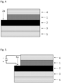
- Fig. 4 is a schematic representation of the bonded composite according to the invention in a preferred embodiment.
- the adhesive tape is arranged via the adhesive layer D 1 on a surface of the first substrate A 4, wherein the first substrate is electrically conductive.
- the adhesive tape is arranged via the second adhesive layer C 3 on a surface of a second substrate B 5.
- Fig. 4 It is also shown by way of example that the electrically conductive carrier layer T 2 projects laterally beyond the adhesive layer D 1 in at least one extension direction of the layer plane, so that the electrically conductive carrier layer T has a projection with a free surface 2 a.
- a voltage can now be applied across this free surface 2a, as shown in the schematic diagram according to Fig. 5 shown.
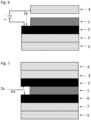
- Fig. 7 is a further schematic representation of the bonded composite according to the invention in a preferred embodiment.
- the adhesive tape is arranged over the adhesive layer C 3 on a surface of the first substrate A 4.
- the adhesive tape is arranged via the third adhesive layer C' 7 on a surface of a second substrate B 5.
- the electrically removable adhesive layer D 1 and two electrically conductive carrier layers T 2 and T' 6, with the layer D 1 being arranged between the carrier layers.
- Fig. 7 It is also shown by way of example that the electrically conductive carrier layer T 2 and the electrically conductive carrier layer T' 6 each project laterally beyond the adhesive layer D 1 in at least one direction of extension of the layer plane, so that the electrically conductive carrier layer T has a projection with a free surface 2a and the electrically conductive carrier layer T' has a projection with a free surface 6a.
- Fig. 8 is a further schematic representation of the bonded composite according to the invention in a preferred embodiment, which corresponds to the representation according to
- Fig. 7 is similar. Unlike Fig. 7 However, the projections of the electrically conductive carrier layer T 2 and the electrically conductive carrier layer T' 6 point in different directions, so that the resulting free surfaces of these layers 2a and 6a are spatially separated.
- a voltage can now be applied across these free surfaces 2a and 6a, analogous to Figure 5 In contrast to the embodiment according to Figure 5
- the voltage can be applied to the Surfaces 2a and 6a so that none of the substrates A and B need be electrically conductive.
- Applying the voltage causes the electrolyte to migrate, in particular the anions and cations of an ionic liquid to separate, in the adhesive layer D 1. This greatly reduces the adhesion of the adhesive layer D 1 to the carrier layers T 2 and/or T' 6 and causes these layers to separate from one another. In particular, detachment occurs at the layer to which the negative pole is applied.
- Fig. 1 to 8 are, as stated, schematic representations.
- the layer thicknesses of the individual layers D, T and C can differ from one another.
- the substrates A and B are only shown schematically as additional layers. These can of course have any other spatial geometry.
- the thickness of an adhesive layer can be determined by determining the thickness of a section of such an adhesive layer applied to a liner, defined in terms of its length and width, minus the (known or separately ascertainable) thickness of a section of the same dimensions of the liner used.
- the thickness of the adhesive layer can be determined using commercially available thickness measuring devices (probe testers) with an accuracy of less than 1 ⁇ m deviation. If thickness fluctuations are determined, the average value of measurements at at least three representative locations is given, i.e. in particular not measured at creases, folds, spots and the like.
- the thickness of an adhesive tape can be determined analogously using commercially available thickness measuring devices (probe testers) with an accuracy of less than 1 ⁇ m deviation. If thickness fluctuations are detected, the average value of measurements at at least three representative locations is given, i.e. in particular not measured at creases, folds, spots and the like.
- the bond strength of the bonded composite is determined for the adhesive tapes to be tested as a parameter for the quality of the bond achieved.
- the test specimens used are made of steel and were cleaned with acetone before bonding. The provision of the test specimens and the layer thicknesses of the adhesive tapes correspond to the information given below.
- an adhesive tape according to the invention comprising at least one adhesive layer D was produced in the form of a transfer adhesive tape, bonded between substrates and then electrically released again by applying a voltage.
- the adhesive of layer D was a heat-activatable adhesive that was not pressure-sensitively adhesive before activation.
- the adhesive layer D was provided as follows: 43% by weight of Nipol 1001CG (nitrile rubber) from Zeon, 40% by weight of novolak resin Durez 33040 mixed with 8% HMTA (Rohm and Haas) and 10% by weight of the resol resin 9610 LW from Bakelite were prepared as a 30% solution in methyl ethyl ketone in a kneader. The kneading time was 20 hours.
- ionic liquid 1-ethyl-3-methylimidazolium bis(trifluoromethylsulfonyl)imide EMIM-TFSI
- EMIM-TFSI 7.0 wt. % of the ionic liquid 1-ethyl-3-methylimidazolium bis(trifluoromethylsulfonyl)imide
- the heat-activated adhesive was then spread from solution onto a glassine release paper and dried at 80°C for 15 minutes. After drying, the layer thickness was 30 ⁇ m.
- the transfer adhesive tape consisting of the adhesive layer D was bonded between two steel plates as follows: Three pieces measuring approximately 15 x 25 mm were cut out of the adhesive tape to be tested (covered on one side with release paper).
- a steel test specimen (substrate) was placed on a hot plate preheated to 105 °C. After approx. 5 seconds of heating, the open side of the adhesive tape sample not covered with release paper was applied to a surface of the test specimen using tweezers and pressed down flat with a rubber roller.
- Example 1 heating was carried out for 8 minutes to a temperature of 120 °C at a pressure of 5 bar.
- the obtained specimens were stored for 24 hours at RT and 50% RH (standard climate).
- the bond strength was determined according to the method given above and was 8.0 MPa.
- Example 1 a sample of the above-mentioned Example 1 was again prepared and tested for electrical re-detachability.
- the voltage was 48 V and was applied for 5 minutes.
- the bond strength was determined according to the method given above and was 3.9 MPa.
Landscapes
- Chemical & Material Sciences (AREA)
- Organic Chemistry (AREA)
- Health & Medical Sciences (AREA)
- Chemical Kinetics & Catalysis (AREA)
- Medicinal Chemistry (AREA)
- Polymers & Plastics (AREA)
- Adhesive Tapes (AREA)
- Adhesives Or Adhesive Processes (AREA)
Priority Applications (4)
| Application Number | Priority Date | Filing Date | Title |
|---|---|---|---|
| EP23191060.5A EP4506430A1 (fr) | 2023-08-11 | 2023-08-11 | Ruban adhésif, composite collé et procédé de libération électrique du composite collé |
| KR1020267007268A KR20260047617A (ko) | 2023-08-11 | 2024-08-01 | 접착 테이프, 본딩된 어셈블리, 및 본딩된 어셈블리를 전기적으로 분해하는 방법 |
| CN202480052989.2A CN121729465A (zh) | 2023-08-11 | 2024-08-01 | 胶带、经粘合的组件和用于电解除经粘合的组件的方法 |
| PCT/EP2024/071772 WO2025036715A1 (fr) | 2023-08-11 | 2024-08-01 | Ruban adhésif, ensemble lié et procédé de dissolution électrique de l'ensemble lié |
Applications Claiming Priority (1)
| Application Number | Priority Date | Filing Date | Title |
|---|---|---|---|
| EP23191060.5A EP4506430A1 (fr) | 2023-08-11 | 2023-08-11 | Ruban adhésif, composite collé et procédé de libération électrique du composite collé |
Publications (1)
| Publication Number | Publication Date |
|---|---|
| EP4506430A1 true EP4506430A1 (fr) | 2025-02-12 |
Family
ID=87571109
Family Applications (1)
| Application Number | Title | Priority Date | Filing Date |
|---|---|---|---|
| EP23191060.5A Withdrawn EP4506430A1 (fr) | 2023-08-11 | 2023-08-11 | Ruban adhésif, composite collé et procédé de libération électrique du composite collé |
Country Status (4)
| Country | Link |
|---|---|
| EP (1) | EP4506430A1 (fr) |
| KR (1) | KR20260047617A (fr) |
| CN (1) | CN121729465A (fr) |
| WO (1) | WO2025036715A1 (fr) |
Citations (7)
| Publication number | Priority date | Publication date | Assignee | Title |
|---|---|---|---|---|
| US20040204551A1 (en) * | 2003-03-04 | 2004-10-14 | L&L Products, Inc. | Epoxy/elastomer adduct, method of forming same and materials and articles formed therewith |
| WO2013174650A1 (fr) | 2012-05-21 | 2013-11-28 | Tesa Se | Matière adhésive thermoactivable absorbant la lumière et ruban adhésif contenant une matière adhésive de ce type |
| EP3031875B1 (fr) | 2013-09-27 | 2018-11-28 | Lintec Corporation | Composition d'agent adhésif électriquement pelable, feuille adhésive électriquement pelable, et procédé d'utilisation de feuille adhésive électriquement pelable |
| US20210277286A1 (en) * | 2018-09-03 | 2021-09-09 | Nitto Denko Corporation | Adhesive composition, adhesive sheet, and adhered body |
| CN114644898A (zh) * | 2020-12-18 | 2022-06-21 | 达迈科技股份有限公司 | 热硬化型抗静电的黏着片 |
| US20220195259A1 (en) * | 2020-02-18 | 2022-06-23 | Vigteqnos Co., Ltd. | Electrically peelable adhesive composition, electrically peelable adhesive product, and method for peeling product |
| US20220411673A1 (en) * | 2019-12-13 | 2022-12-29 | Henkel Ag & Co. Kgaa | One component (1k) curable adhesive composition |
Family Cites Families (1)
| Publication number | Priority date | Publication date | Assignee | Title |
|---|---|---|---|---|
| CN115895519A (zh) * | 2022-11-29 | 2023-04-04 | 苏州高泰电子技术股份有限公司 | 电解粘胶黏剂以及双面胶带 |
-
2023
- 2023-08-11 EP EP23191060.5A patent/EP4506430A1/fr not_active Withdrawn
-
2024
- 2024-08-01 CN CN202480052989.2A patent/CN121729465A/zh active Pending
- 2024-08-01 KR KR1020267007268A patent/KR20260047617A/ko active Pending
- 2024-08-01 WO PCT/EP2024/071772 patent/WO2025036715A1/fr active Pending
Patent Citations (7)
| Publication number | Priority date | Publication date | Assignee | Title |
|---|---|---|---|---|
| US20040204551A1 (en) * | 2003-03-04 | 2004-10-14 | L&L Products, Inc. | Epoxy/elastomer adduct, method of forming same and materials and articles formed therewith |
| WO2013174650A1 (fr) | 2012-05-21 | 2013-11-28 | Tesa Se | Matière adhésive thermoactivable absorbant la lumière et ruban adhésif contenant une matière adhésive de ce type |
| EP3031875B1 (fr) | 2013-09-27 | 2018-11-28 | Lintec Corporation | Composition d'agent adhésif électriquement pelable, feuille adhésive électriquement pelable, et procédé d'utilisation de feuille adhésive électriquement pelable |
| US20210277286A1 (en) * | 2018-09-03 | 2021-09-09 | Nitto Denko Corporation | Adhesive composition, adhesive sheet, and adhered body |
| US20220411673A1 (en) * | 2019-12-13 | 2022-12-29 | Henkel Ag & Co. Kgaa | One component (1k) curable adhesive composition |
| US20220195259A1 (en) * | 2020-02-18 | 2022-06-23 | Vigteqnos Co., Ltd. | Electrically peelable adhesive composition, electrically peelable adhesive product, and method for peeling product |
| CN114644898A (zh) * | 2020-12-18 | 2022-06-21 | 达迈科技股份有限公司 | 热硬化型抗静电的黏着片 |
Also Published As
| Publication number | Publication date |
|---|---|
| CN121729465A (zh) | 2026-03-24 |
| KR20260047617A (ko) | 2026-04-08 |
| WO2025036715A1 (fr) | 2025-02-20 |
Similar Documents
| Publication | Publication Date | Title |
|---|---|---|
| DE69813103T2 (de) | Mehrschichtiger, anisotroper und elektrisch leitender Klebstoff und Verfahren zu dessen Herstellung | |
| EP2742106B1 (fr) | Matière adhésive électroconductrice et bande adhésive | |
| EP2820098A1 (fr) | Utilisation d'un film adhésif à réactivité latente pour le collage de plastique sur de l'aluminium anodisé | |
| EP3137566B1 (fr) | Procédé pour réaliser un collage sur des surfaces sensibles aux perméats | |
| WO2010063498A1 (fr) | Thermoplastes étirés pour collage de pièces métalliques sur des matières plastiques, des verres, et des métaux, et leur procédé de fabrication | |
| DE19853805B4 (de) | Elektrisch leitfähige, thermoplastische und hitzeaktivierbare Klebstofffolie und deren Verwendung | |
| DE202012004946U1 (de) | Lichtabsorbierende hitzeaktivierbare Klebemasse und Klebeband enthaltend solche Klebemasse | |
| DE102006055093A1 (de) | Hitze-aktiviert verklebbares Flächenelement | |
| DE102009025641A1 (de) | Verwendung von hitzeaktivierbaren Klebebändern für die Verklebung von flexiblen Leiterplatten | |
| DE102014208109A1 (de) | Spaltbares Klebend mit dosierfähigen spaltbaren Flüssigklebstoff | |
| DE102004029589A1 (de) | Elektrisch anisotrop leitfähiger Schmelzkleber zur Implantierung von elektrischen Modulen in einen Kartenkörper | |
| WO2020108765A1 (fr) | Film adhésif à réactivité latente à base de polyuréthane | |
| EP1078965B1 (fr) | Feuille adhésive thermo-activable et procédé pour la préparation d'assemblages structurels | |
| EP4486807A1 (fr) | Composition d'adhésif sensible à la pression | |
| DE102007063020A1 (de) | Verfahren zur Herstellung eines Antennensystems | |
| EP4506430A1 (fr) | Ruban adhésif, composite collé et procédé de libération électrique du composite collé | |
| EP4455237A1 (fr) | Ruban adhésif, composite collé et procédé de libération électrique du composite collé | |
| WO2025036719A1 (fr) | Ruban adhésif, unité liée de manière adhésive et procédé de décollement électrique de l'unité collée | |
| WO2022073609A1 (fr) | Film adhésif sensible à la pression défini géométriquement | |
| WO2019105911A1 (fr) | Film adhésif réactif latent comprenant un composant pouvant réduire la tension superficielle ou la tension interfaciale | |
| EP0846743A1 (fr) | Feuille autocollante thermoplastique | |
| DE102023120290A1 (de) | Haftklebemasse, Klebeband, verklebter Verbund und Verfahren zum elektrischen Lösen des verklebten Verbundes | |
| DE102013009234B4 (de) | Verfahren zur Herstellung elektrisch leitender Verbindungen zwischen Fügepartnern sowie eine Verwendung eines Polymers oder Polymergemischs | |
| EP4592370A1 (fr) | Ruban adhésif, composite collé et procédé de libération électrique du composite collé | |
| EP4685204A1 (fr) | Matière adhésive, bande adhésive, composite collé et procédé de décollage électrique de la matière composite collée |
Legal Events
| Date | Code | Title | Description |
|---|---|---|---|
| PUAI | Public reference made under article 153(3) epc to a published international application that has entered the european phase |
Free format text: ORIGINAL CODE: 0009012 |
|
| STAA | Information on the status of an ep patent application or granted ep patent |
Free format text: STATUS: THE APPLICATION HAS BEEN PUBLISHED |
|
| AK | Designated contracting states |
Kind code of ref document: A1 Designated state(s): AL AT BE BG CH CY CZ DE DK EE ES FI FR GB GR HR HU IE IS IT LI LT LU LV MC ME MK MT NL NO PL PT RO RS SE SI SK SM TR |
|
| STAA | Information on the status of an ep patent application or granted ep patent |
Free format text: STATUS: THE APPLICATION HAS BEEN WITHDRAWN |
|
| 18W | Application withdrawn |
Effective date: 20250710 |