EP4506501A1 - Waschmaschine und steuerungsverfahren für waschmaschine - Google Patents
Waschmaschine und steuerungsverfahren für waschmaschine Download PDFInfo
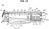
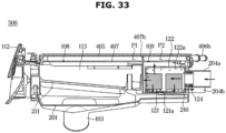
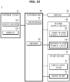
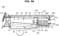
- Publication number
- EP4506501A1 EP4506501A1 EP23831735.8A EP23831735A EP4506501A1 EP 4506501 A1 EP4506501 A1 EP 4506501A1 EP 23831735 A EP23831735 A EP 23831735A EP 4506501 A1 EP4506501 A1 EP 4506501A1
- Authority
- EP
- European Patent Office
- Prior art keywords
- water
- filter
- washing machine
- tub
- water supply
- Prior art date
- Legal status (The legal status is an assumption and is not a legal conclusion. Google has not performed a legal analysis and makes no representation as to the accuracy of the status listed.)
- Pending
Links
Images






















Classifications
-
- D—TEXTILES; PAPER
- D06—TREATMENT OF TEXTILES OR THE LIKE; LAUNDERING; FLEXIBLE MATERIALS NOT OTHERWISE PROVIDED FOR
- D06F—LAUNDERING, DRYING, IRONING, PRESSING OR FOLDING TEXTILE ARTICLES
- D06F39/00—Details of washing machines not specific to a single type of machines covered by groups D06F9/00 - D06F27/00
- D06F39/10—Filtering arrangements
-
- B—PERFORMING OPERATIONS; TRANSPORTING
- B01—PHYSICAL OR CHEMICAL PROCESSES OR APPARATUS IN GENERAL
- B01D—SEPARATION
- B01D29/00—Filters with filtering elements stationary during filtration, e.g. pressure or suction filters, not covered by groups B01D24/00 - B01D27/00; Filtering elements therefor
- B01D29/11—Filters with filtering elements stationary during filtration, e.g. pressure or suction filters, not covered by groups B01D24/00 - B01D27/00; Filtering elements therefor with bag, cage, hose, tube, sleeve or like filtering elements
- B01D29/31—Self-supporting filtering elements
- B01D29/33—Self-supporting filtering elements arranged for inward flow filtration
-
- B—PERFORMING OPERATIONS; TRANSPORTING
- B01—PHYSICAL OR CHEMICAL PROCESSES OR APPARATUS IN GENERAL
- B01D—SEPARATION
- B01D29/00—Filters with filtering elements stationary during filtration, e.g. pressure or suction filters, not covered by groups B01D24/00 - B01D27/00; Filtering elements therefor
- B01D29/62—Regenerating the filter material in the filter
-
- B—PERFORMING OPERATIONS; TRANSPORTING
- B01—PHYSICAL OR CHEMICAL PROCESSES OR APPARATUS IN GENERAL
- B01D—SEPARATION
- B01D35/00—Filtering devices having features not specifically covered by groups B01D24/00 - B01D33/00, or for applications not specifically covered by groups B01D24/00 - B01D33/00; Auxiliary devices for filtration; Filter housing constructions
- B01D35/02—Filters adapted for location in special places, e.g. pipe-lines, pumps, stop-cocks
-
- D—TEXTILES; PAPER
- D06—TREATMENT OF TEXTILES OR THE LIKE; LAUNDERING; FLEXIBLE MATERIALS NOT OTHERWISE PROVIDED FOR
- D06F—LAUNDERING, DRYING, IRONING, PRESSING OR FOLDING TEXTILE ARTICLES
- D06F39/00—Details of washing machines not specific to a single type of machines covered by groups D06F9/00 - D06F27/00
- D06F39/02—Devices for adding soap or other washing agents
-
- D—TEXTILES; PAPER
- D06—TREATMENT OF TEXTILES OR THE LIKE; LAUNDERING; FLEXIBLE MATERIALS NOT OTHERWISE PROVIDED FOR
- D06F—LAUNDERING, DRYING, IRONING, PRESSING OR FOLDING TEXTILE ARTICLES
- D06F39/00—Details of washing machines not specific to a single type of machines covered by groups D06F9/00 - D06F27/00
- D06F39/08—Liquid supply or discharge arrangements
- D06F39/083—Liquid discharge or recirculation arrangements
-
- D—TEXTILES; PAPER
- D06—TREATMENT OF TEXTILES OR THE LIKE; LAUNDERING; FLEXIBLE MATERIALS NOT OTHERWISE PROVIDED FOR
- D06F—LAUNDERING, DRYING, IRONING, PRESSING OR FOLDING TEXTILE ARTICLES
- D06F39/00—Details of washing machines not specific to a single type of machines covered by groups D06F9/00 - D06F27/00
- D06F39/08—Liquid supply or discharge arrangements
- D06F39/088—Liquid supply arrangements
-
- D—TEXTILES; PAPER
- D06—TREATMENT OF TEXTILES OR THE LIKE; LAUNDERING; FLEXIBLE MATERIALS NOT OTHERWISE PROVIDED FOR
- D06F—LAUNDERING, DRYING, IRONING, PRESSING OR FOLDING TEXTILE ARTICLES
- D06F2101/00—User input for the control of domestic laundry washing machines, washer-dryers or laundry dryers
- D06F2101/20—Operation modes, e.g. delicate laundry washing programs, service modes or refreshment cycles
-
- D—TEXTILES; PAPER
- D06—TREATMENT OF TEXTILES OR THE LIKE; LAUNDERING; FLEXIBLE MATERIALS NOT OTHERWISE PROVIDED FOR
- D06F—LAUNDERING, DRYING, IRONING, PRESSING OR FOLDING TEXTILE ARTICLES
- D06F2105/00—Systems or parameters controlled or affected by the control systems of washing machines, washer-dryers or laundry dryers
- D06F2105/02—Water supply
-
- D—TEXTILES; PAPER
- D06—TREATMENT OF TEXTILES OR THE LIKE; LAUNDERING; FLEXIBLE MATERIALS NOT OTHERWISE PROVIDED FOR
- D06F—LAUNDERING, DRYING, IRONING, PRESSING OR FOLDING TEXTILE ARTICLES
- D06F2105/00—Systems or parameters controlled or affected by the control systems of washing machines, washer-dryers or laundry dryers
- D06F2105/08—Draining of washing liquids
-
- D—TEXTILES; PAPER
- D06—TREATMENT OF TEXTILES OR THE LIKE; LAUNDERING; FLEXIBLE MATERIALS NOT OTHERWISE PROVIDED FOR
- D06F—LAUNDERING, DRYING, IRONING, PRESSING OR FOLDING TEXTILE ARTICLES
- D06F23/00—Washing machines with receptacles, e.g. perforated, having a rotary movement, e.g. oscillatory movement, the receptacle serving both for washing and for centrifugally separating water from the laundry
- D06F23/02—Washing machines with receptacles, e.g. perforated, having a rotary movement, e.g. oscillatory movement, the receptacle serving both for washing and for centrifugally separating water from the laundry and rotating or oscillating about a horizontal axis
-
- D—TEXTILES; PAPER
- D06—TREATMENT OF TEXTILES OR THE LIKE; LAUNDERING; FLEXIBLE MATERIALS NOT OTHERWISE PROVIDED FOR
- D06F—LAUNDERING, DRYING, IRONING, PRESSING OR FOLDING TEXTILE ARTICLES
- D06F33/00—Control of operations performed in washing machines or washer-dryers
- D06F33/30—Control of washing machines characterised by the purpose or target of the control
- D06F33/32—Control of operational steps, e.g. optimisation or improvement of operational steps depending on the condition of the laundry
- D06F33/34—Control of operational steps, e.g. optimisation or improvement of operational steps depending on the condition of the laundry of water filling
-
- D—TEXTILES; PAPER
- D06—TREATMENT OF TEXTILES OR THE LIKE; LAUNDERING; FLEXIBLE MATERIALS NOT OTHERWISE PROVIDED FOR
- D06F—LAUNDERING, DRYING, IRONING, PRESSING OR FOLDING TEXTILE ARTICLES
- D06F33/00—Control of operations performed in washing machines or washer-dryers
- D06F33/30—Control of washing machines characterised by the purpose or target of the control
- D06F33/32—Control of operational steps, e.g. optimisation or improvement of operational steps depending on the condition of the laundry
- D06F33/42—Control of operational steps, e.g. optimisation or improvement of operational steps depending on the condition of the laundry of draining
-
- D—TEXTILES; PAPER
- D06—TREATMENT OF TEXTILES OR THE LIKE; LAUNDERING; FLEXIBLE MATERIALS NOT OTHERWISE PROVIDED FOR
- D06F—LAUNDERING, DRYING, IRONING, PRESSING OR FOLDING TEXTILE ARTICLES
- D06F33/00—Control of operations performed in washing machines or washer-dryers
- D06F33/30—Control of washing machines characterised by the purpose or target of the control
- D06F33/43—Control of cleaning or disinfection of washing machine parts, e.g. of tubs
-
- D—TEXTILES; PAPER
- D06—TREATMENT OF TEXTILES OR THE LIKE; LAUNDERING; FLEXIBLE MATERIALS NOT OTHERWISE PROVIDED FOR
- D06F—LAUNDERING, DRYING, IRONING, PRESSING OR FOLDING TEXTILE ARTICLES
- D06F33/00—Control of operations performed in washing machines or washer-dryers
- D06F33/30—Control of washing machines characterised by the purpose or target of the control
- D06F33/44—Control of the operating time, e.g. reduction of overall operating time
-
- D—TEXTILES; PAPER
- D06—TREATMENT OF TEXTILES OR THE LIKE; LAUNDERING; FLEXIBLE MATERIALS NOT OTHERWISE PROVIDED FOR
- D06F—LAUNDERING, DRYING, IRONING, PRESSING OR FOLDING TEXTILE ARTICLES
- D06F34/00—Details of control systems for washing machines, washer-dryers or laundry dryers
- D06F34/28—Arrangements for program selection, e.g. control panels therefor; Arrangements for indicating program parameters, e.g. the selected program or its progress
- D06F34/30—Arrangements for program selection, e.g. control panels therefor; Arrangements for indicating program parameters, e.g. the selected program or its progress characterised by mechanical features, e.g. buttons or rotary dials
-
- D—TEXTILES; PAPER
- D06—TREATMENT OF TEXTILES OR THE LIKE; LAUNDERING; FLEXIBLE MATERIALS NOT OTHERWISE PROVIDED FOR
- D06F—LAUNDERING, DRYING, IRONING, PRESSING OR FOLDING TEXTILE ARTICLES
- D06F34/00—Details of control systems for washing machines, washer-dryers or laundry dryers
- D06F34/28—Arrangements for program selection, e.g. control panels therefor; Arrangements for indicating program parameters, e.g. the selected program or its progress
- D06F34/32—Arrangements for program selection, e.g. control panels therefor; Arrangements for indicating program parameters, e.g. the selected program or its progress characterised by graphical features, e.g. touchscreens
-
- D—TEXTILES; PAPER
- D06—TREATMENT OF TEXTILES OR THE LIKE; LAUNDERING; FLEXIBLE MATERIALS NOT OTHERWISE PROVIDED FOR
- D06F—LAUNDERING, DRYING, IRONING, PRESSING OR FOLDING TEXTILE ARTICLES
- D06F37/00—Details specific to washing machines covered by groups D06F21/00 - D06F25/00
- D06F37/02—Rotary receptacles, e.g. drums
- D06F37/04—Rotary receptacles, e.g. drums adapted for rotation or oscillation about a horizontal or inclined axis
- D06F37/06—Ribs, lifters, or rubbing means forming part of the receptacle
Definitions
- the present disclosure relates to a washing machine having a filter and a control method of the washing machine.
- a washing machine is an apparatus for performing washing through friction by stirring laundry, water, and a detergent together inside a tub with a driving force of a driving motor.
- Operations that are performed by a washing machine include a washing operation of supplying a detergent and water to a tub accommodating laundry and washing the laundry while rotating a drum, a rinsing operation of rinsing the laundry by supplying water to the tub and rotating the drum, and a dehydrating operation of discharging water from the tub and rotating the drum to remove water from the laundry, regardless of the kind of the washing machine.
- the washing machine includes a pump device for discharging water stored in the tub to the outside of the washing machine during the washing operation, the rinsing operation, and/or the dehydrating operation.
- the pump device is configured to return water discharged from the tub to the tub during the washing operation and/or the rinsing operation.
- the washing machine may include a filter for filtering out foreign materials included in water discharged from the pump device.
- An aspect of the disclosure provides a washing machine capable of increasing a replacement cycle of a filter.
- a washing machine may include a housing, a tub provided inside the housing, a detergent supplier connected to the tub, and a water supply guide configured to guide water to the detergent supplier.
- the detergent supplier may include a drawer configured to accommodate a detergent, a filter detachably installed in the drawer, and a drawer case configured to accommodate the drawer.
- the drawer case may include a washing hole configured to guide a part of water supplied to the drawer case to the filter and supply water to an outer side of the filter, the outer side being opposite to an inner side of the filter where foreign materials are collected.
- the drawer may include a detergent accommodating portion configured to accommodate the detergent.
- the drawer case may include a water supply hole configured to guide a part of water supplied to the drawer case to the detergent accommodating portion.
- the washing machine may further include a pump device configured to move water discharged from the tub to the tub.
- the filter may be positioned to filter water moving from the pump device to the tub.
- the drawer case may include a tub port configured to discharge water supplied to the drawer through the water supply hole, together with a detergent, to the tub.
- the tub port may be configured to guide water supplied to the filter through the washing hole to the tub.
- the water supply guide may be positioned closer to the washing hole than the water supply hole.
- the washing machine may further include a valve configured to open or close the water supply guide, and a controller configured to control the valve.
- the controller may be configured to open the valve for a preset time during a drain operation.
- the valve may be an electronic valve of which an opening rate is adjusted.
- the controller may be configured to fully open the electronic valve during a water supply operation, and partially open the electronic valve for the preset time during the drain operation.
- the water supply guide may include a first guide configured to guide water to the water supply hole and a second guide configured to guide water to the washing hole.
- the washing machine may further include a first valve configured to open or close the first guide, a second valve configured to open or close the second guide, and a controller configured to control the first valve and the second valve.
- the controller may be configured to open the second valve for a preset time based on reception of a user input to clean the filter.
- the controller may be configured to open the second valve for a preset time during a drain operation.
- the washing machine may further include a pump device configured to move water discharged from the tub to the tub.
- the filter may be positioned to filter water moving from the pump device to the tub.
- the controller may be configured to open the second valve for a preset time based on a termination operation of the pump device.
- the filter may be positioned behind the detergent accommodating portion.
- the water supply hole may be positioned above the detergent accommodating portion.
- the washing hole may be positioned above the filter.
- the washing machine may further include a pump device configured to move water discharged from the tub to outside of the housing.
- the filter may be positioned to filter water moving from the pump device to the outside of the housing.
- the drawer case may include a case outlet configured to discharge water passed through the filter to outside of the drawer case.
- the case outlet may be configured to guide water supplied to the filter through the washing hole to the outside of the drawer case.
- a washing machine may include a tub and a detergent supplier connected to the tub.
- the detergent supplier may include a drawer case, a drawer including a detergent accommodating portion that accommodates a detergent and configured to be inserted into the drawer case or withdrawn from the drawer case, and a filter detachably installed in the drawer.
- the drawer case may include a water supply hole configured to guide a part of water supplied to the drawer case to the detergent accommodating portion, and a washing hole configured to guide another part of the water supplied to the drawer case to the filter and supply water to an outer side of the filter, the outer side being opposite to an inner side of the filter where foreign materials are filtered out.
- the drawer case may include a tub port configured to discharge a detergent of the drawer to the tub, wherein the tub port may guide water supplied to the filter through the washing hole to the tub.
- the drawer case may include a case outlet configured to discharge water passed through the filter to outside of the drawer case, wherein the case outlet may guide water supplied to the filter through the washing hole to the outside of the drawer case.
- a control method of a washing machine including a detergent supplier including a drawer and a filter may include opening a water supply guide for supplying water to the detergent supplier for a preset time during a drain operation.
- the water supply guide may include a first guide configured to guide water to the drawer and a second guide to guide water to the filter.
- the opening of the water supply guide may include opening the second guide for the preset time during the drain operation.
- a washing machine may increase a replacement cycle of a filter by supplying water to the filter to wash a part of a filter surface.
- phrases, such as “A or B”, “at least one of A and B”, “at least one of A or B,” “A, B or C,” “at least one of A, B and C,” and “at least one of A, B, or C”, may include any one or all possible combinations of items listed together in the corresponding phrase among the phrases.
- a certain (e.g., a first) component is referred to as “coupled” or “connected” with or without the terms “functionally” or “communicatively” to another (e.g., second) component.
- a certain component e.g., a first
- another component e.g., second
- any of the above components can be connected to the other components directly (e.g., by wire), wirelessly, or via a third component.
- a washing machine may be an example of a clothes processing apparatus.
- a washing machine may include a top-loading washing machine in which an inlet for allowing a user to put laundry in or take laundry out faces upward, or a front-loading washing machine in which an inlet for allowing a user to put laundry in or take laundry out faces forward.
- the washing machine according to various embodiments may include another type of washing machine, other than the top-loading washing machine and the front-loading washing machine.
- the top-loading washing machine may wash laundry by using a water stream generated by a rotating body such as a pulsator.
- the front-loading washing machine may wash laundry by rotating a drum to repeatedly lift and drop the laundry.
- the front-loading washing machine may include a lifter for lifting laundry.
- the washing machine according to various embodiments may include a washing machine using another washing method other than the above-described washing methods.
- FIG. 1 shows a washing machine according to an embodiment.
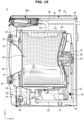
- FIG. 2 shows a cross section of the washing machine shown in FIG. 1 .
- a washing machine 1 may include a housing 10 that accommodates various components therein.
- the housing 10 may include a housing opening 11 for allowing an access to inside of a drum 30.
- a tub 20 may include a tub opening 21 corresponding to the housing opening 11.
- the drum 30 may include a drum opening 31 corresponding to the housing opening 11 and the tub opening 21. Laundry may be put in the drum 30 or taken out of the drum 30 through the housing opening 11, the tub opening 21, and the drum opening 31.
- the housing opening 11 may face substantially forward.
- the tub opening 21 may face substantially forward.
- the drum opening 31 may face substantially forward.
- the washing machine 1 may include a control panel 14.
- the control panel 14 may be provided on the housing 10.
- the control panel 14 may include an input device 14a for receiving an operation command from a user, and a display 14b for displaying operation information of the washing machine 1.
- the control panel 14 may provide a user interface for enabling a user to interact with the washing machine 1.
- the input device 14a may provide an electrical output signal corresponding to a user input to a controller 90 (see FIGS. 8 , 14 , 23 , 29 , 35 , and 43 ).
- the input device 14a may include, for example, a power button, a start button, a course selection dial (or a course selection button), and a washing/rinsing/dehydrating setting button.
- An input button may include, for example, a tact switch, a push switch, a slide switch, a toggle switch, a micro switch, or a touch switch.
- the display 14b may receive a signal from the controller 90, and display information corresponding to the received signal.
- the display 14b may include a screen that displays a washing course selected by a rotation of the course selection dial (or, pressing of the course selection button) and an operation time of the washing machine 1, and an indicator that displays a washing setting/rinsing setting/dehydrating setting selected by the setting button.
- the display 14b may include, for example, a Liquid Crystal Display (LCD) panel, a Light Emitting Diode (LED) panel, etc.
- the washing machine 1 may include a door 40 for opening or closing the housing opening 11 provided in the housing 10.
- the door 40 may be rotatably installed on the housing 10 by a hinge 41. At least a portion of the door 40 may be transparent or translucent to show inside of the housing 10.
- the washing machine 1 may include the tub 20 provided inside the housing 10 to store water.
- the tub 20 may be supported on an inner side of the housing 10.
- the tub 20 may be substantially in a shape of a cylinder of which one side opens.
- the tub 20 may be elastically supported from the housing 10 by a damper 29.
- the damper 29 may connect the tub 20 to the housing 10.
- the damper 29 may attenuate vibration generated during a rotation of the drum 30 by absorbing vibration energy between the tub 20 and the housing 10 upon transferring of the vibration to the tub 20 and/or the housing 10.
- the washing machine 1 may include the drum 30 that accommodates laundry.
- the drum 30 may be rotatably provided inside the tub 20.
- the drum 30 may perform washing, rinsing, and/or dehydrating, while rotating inside the tub 20.
- the drum 30 may include a through hole 34 that connects an inside space of the drum 30 to an inside space of the tub 20.
- the drum 30 may be substantially in a shape of a cylinder of which one side opens.
- On an inner circumferential surface of the drum 30, a plurality of lifters 35 may be provided to lift and drop laundry upon a rotation of the drum 30.
- the washing machine 1 may include a driver 50 configured to rotate the drum 30.
- the driver 50 may include a driving motor 51, and a rotating shaft 56 for transferring a driving force generated from the driving motor 51 to the drum 30.
- the rotating shaft 56 may penetrate the tub 20 and be connected to the drum 30.
- the driver 50 may rotate the drum 30 forward or backward to perform a washing, rinsing, and/or dehydrating operation.
- the drum 30 may be connected to the driving motor 51 through the rotating shaft 56, and according to connection types between the rotating shaft 56 and the driving motor 51, there may be a direct driving type in which the rotating shaft 56 is directly connected to the driving motor 51 to rotate the drum 30, and an indirect driving type in which pulleys 52 and 57 are connected between the driving motor 51 and the rotating shaft 56 to drive the drum 30.
- FIG. 2 shows a case in which the washing machine 1 is the indirect driving type.
- the washing machine 1 according to various embodiments may be the direct driving type.
- the washing machine 1 may be the indirect driving type.
- One end of the rotating shaft 56 may be connected to a rear portion of the drum 30, and the other end of the rotating shaft 56 may be connected to a shaft pulley 57 to obtain a driving force from the driving motor 51.
- a motor pulley 52 may be formed on a rotating shaft of the driving motor 51.
- a driving belt 53 may be provided between the motor pulley 52 and the shaft pulley 57, and the rotating shaft 56 may be driven by the driving belt 53.
- the driving motor 51 may be positioned below the tub 20.
- the driving belt 53 may drive the rotating shaft 56 while rotating clockwise or counterclockwise in an up-down direction of the tub 20.
- a bearing housing 58 for rotatably supporting the rotating shaft 56 may be installed in the rear portion of the tub 20 in the rear portion of the tub 20, a bearing housing 58 for rotatably supporting the rotating shaft 56 may be installed.
- the bearing housing 58 may be made of an aluminum alloy.
- the bearing housing 58 may be inserted into the rear portion of the tub 20 upon injection-molding of the tub 20.
- a water supply device 60 may supply water to the tub 20.
- the water supply device 60 may include a water supply guide 61, and a water supply valve 62 provided in the water supply guide 61.
- the water supply guide 61 may be connected to an external water supply source.
- the water supply guide 61 may extend from the external water supply source to a detergent supply device 100 and/or the tub 20.
- the water supply guide 61 may guide water to the detergent supply device 100. Water may be supplied to the tub 20 via the detergent supply device 100. Water may be supplied to the tub 20 without passing through the detergent supply device 100.
- the water supply valve 62 may open or close the water supply guide 61 in response to an electrical signal from the controller 90.
- the water supply valve 62 may allow or block supply of water from the external water supply source to the tub 20.
- the water supply valve 62 may include, for example, a solenoid valve that is opened or closed in response to an electrical signal.
- the washing machine 1 may include a pump device 70.
- the pump device 70 may discharge water accommodated in the tub 20 to the outside.
- the pump device 70 may be connected to the tub 20.
- the washing machine 1 may include a connecting guide 81 connecting the tub 20 to the pump device 70 such that water in the tub 20 flows into the pump device 70.
- the connecting guide 81 may guide water discharged from the tub 20 to the pump device 70.
- a drain 22 for draining water stored in the tub 20 to the outside of the tub 20 may be formed.
- the drain 22 may be connected to the connecting guide 81.
- the washing machine 1 may include a drain guide 82 extending from the pump device 70 to outside of the housing 10 to discharge water entered the pump device 70 to the outside of the housing 10.
- the drain guide 82 may guide water of the pump device 70 to the outside of the housing 10.
- the drain guide 82 may guide water pumped by a drain pump 72 (see FIG. 8 ) provided in the pump device 70.
- the washing machine 1 may include a circulation guide 83 extending from the pump device 70.
- the circulation guide 83 may be connected to the detergent supply device 100.
- the circulation guide 83 may guide water pumped by a circulation pump 71 (see FIG. 8 ) provided in the pump device 70. Water pumped by the circulation pump 71 of the pump device 70 may flow into the tub 20 via the detergent supply device 100.
- the washing machine 1 may include the detergent supply device 100 configured to supply a detergent to the tub 20.
- the detergent supply device 100 may be configured to supply a detergent to the tub 20 during a water supply process. Water supplied through the water supply guide 61 may be mixed with a detergent via the detergent supply device 100. The water mixed with the detergent may be supplied to the tub 20.
- the detergent supply device 100 may be connected to the tub 20 through a tub guide 63.
- the detergent may include a powdered detergent, a liquid detergent, a pre-wash detergent, fabric softener, or bleach.
- the detergent may include a laundry detergent, a dryer rinse, a deodorizer, a disinfectant or an air freshener.
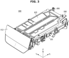
- FIG. 3 shows a detergent supply device shown in FIG. 1 .
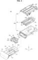
- FIG. 4 is an exploded view of the detergent supply device shown in FIG. 3 .
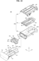
- FIG. 5 shows a drawer shown in FIG. 4 .
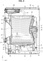
- FIG. 6 shows a flow of water that is filtered by passing through a filter, in a cross section of the detergent supply device shown in FIG. 3 .
- FIG. 7 shows a flow of water that washes the filter, in the cross section of the detergent supply device shown in FIG. 3 .
- the detergent supply device 100 may include a drawer case 100a installed in the housing 10.
- the drawer case 100a may accommodate at least a portion of a drawer 110.
- the drawer case 100a may include a case body 101, a case cover 105, and a case guide 107.
- the case body 101, the case cover 105, and the case guide 107 may be integrated into one body.
- the case body 101 may include a drawer opening 102 through which a portion of the drawer 110 passes.
- the drawer opening 102 may open forward.
- An open upper side of the case body 101 may be covered by the case cover 105.
- the case body 101 may include a tub port 103 connected to the tub guide 63.
- the tub port 103 may be positioned in a lower portion of the case body 101. According to the tub port 103 being connected to the tub guide 63, the drawer case 100a may be connected to the tub 20. Water and/or a detergent in the detergent supply device 100 may be supplied to the tub 20 through the tub port 103.
- the tub port 103 may discharge water supplied to the drawer 110 through a water supply hole 108, together with a detergent, to the tub 20.
- the tub port 103 may guide water supplied to a filter 120 through a washing hole 109 to the tub 20.
- the case body 101 may include a case inlet 104 connected to the circulation guide 83.
- the case inlet 104 may be positioned in a rear portion of the case body 101.
- the drawer case 100a may be connected to the pump device 70. Water discharged from the pump device 70 may flow into the detergent supply device 100 through the case inlet 104.
- the case cover 105 may cover the open upper side of the case body 101.
- the case cover 105 may be installed on the case body 101.
- the case cover 105 may include a water supply port 106.
- the water supply port 106 may be connected to the water supply guide 61. According to the water supply port 106 being connected to the water supply guide 61, water provided from a water supply source may be supplied to the detergent supply device 100.
- the water supply port 106 may include a water supply port for hot water and a water supply port for cold water.
- the case guide 107 may be installed in the case body 101.
- the case guide 107 may be installed in the case cover 105.
- the case guide 107 may be positioned between the case body 101 and the case cover 105.
- the case guide 107 may guide water supplied to the detergent supply device 100 to a detergent accommodating portion 113 and/or the filter 120, together with the case cover 105.
- the case guide 107 may include a guide rib 107a for guiding water received through the water supply port 106.
- the case guide 107 may include the water supply hole 108 that communicates with the detergent accommodating portion 113.
- the water supply hole 108 may be formed toward the detergent accommodating portion 113.
- the water supply hole 108 may be positioned above the detergent accommodating portion 113.
- the water supply hole 108 may discharge a part of water supplied to the detergent supply device 100 through the water supply port 106 to the detergent accommodating portion 113.
- the case guide 107 may include the washing hole 109 formed to communicate with a filter installing portion 116.
- the washing hole 109 may be positioned behind the water supply hole 108.
- the washing hole 109 may be formed toward the filter installing portion 116.
- the washing hole 109 may be positioned above the filter installing portion 116.
- the washing hole 109 may discharge a part of water supplied to the detergent supply device 100 through the water supply port 106 to the filter installing portion 116.
- the washing hole 109 may discharge a part of water supplied to the detergent supply device 100 through the water supply port 106 to the filter 120 positioned in the filter installing portion 116.
- the washing hole 109 may guide a part of water supplied to the drawer case 100a to the filter 120.
- the washing hole 109 may supply water supplied to the drawer case 100a to an outer side of the filter 120, which is opposite to an inner side of the filter 120 where foreign materials are collected.
- the water supply guide 61 may be positioned closer to the washing hole 109 than the water supply hole 108.
- the detergent supply device 100 may include the drawer 110 that is accommodated in the drawer case 100a. At least a portion of the drawer 110 may be accommodated in the drawer case 100a. The drawer 110 may be inserted into or taken out of the drawer case 100a.
- the drawer 110 may include a drawer body 111 that is accommodated in the drawer case 100a, and a drawer handle 112.
- the drawer body 111 may be installed on the drawer handle 112.
- the drawer handle 112 may be exposed to the outside of the housing 10. A user may take the drawer 110 out of the drawer case 100a by using the drawer handle 112.
- the drawer body 111 may include the detergent accommodating portion 113.
- the detergent accommodating portion 113 may accommodate a detergent.
- FIG. 4 shows a plurality of detergent accommodating portions 113. However, a single detergent accommodating portion 113 may be provided. The user may take the drawer 110 out of the drawer case 100a to put a detergent in the detergent accommodating portion 113.
- the drawer body 111 may include a drawer outlet 114 for discharging a detergent and/or water in the detergent accommodating portion 113 to the drawer case 100a.
- the detergent accommodating portion 113 may communicate with a space between the drawer 110 and the drawer case 100a by the drawer outlet 114.
- the drawer outlet 114 may be positioned between the detergent accommodating portion 113 and the filter installing portion 116.
- the drawer body 111 may include the filter installing portion 116 formed to accommodate the filter 120.
- the filter installing portion 116 may be positioned behind the detergent accommodating portion 113.
- a size of the filter installing portion 116 may be greater than a size of the filter 120 to form a space for water passed through the filter 120 between the filter installing portion 116 and the filter 120.
- the drawer outlet 114 may discharge water in the filter installing portion 116 to the drawer case 100a.
- the filter installing portion 116 may communicate with the space between the drawer 110 and the drawer case 100a by the drawer outlet 114.
- the filter installing portion 116 may include a filter inlet accommodating portion 116a in which a filter inlet 124 of the filter 120 is accommodated.
- the filter inlet accommodating portion 116a may extend in a direction in which the filter 120 is installed in the filter installing portion 116.
- the filter inlet accommodating portion 116a may be positioned in a rear portion of the filter installing portion 116.
- the filter inlet accommodating portion 116a may be positioned to correspond to the case inlet 104.
- the detergent supply device 100 may include the filter 120 detachably installed in the drawer 110.
- the filter 120 may be installed in the filter installing portion 116 of the drawer 110.
- the filter 120 may be positioned behind the detergent accommodating portion 113.
- the filter 120 may filter out foreign materials from water discharged from the pump device 70.
- the filter 120 may be positioned to filter water moving from the pump device 70 to the tub 20.
- the filter 120 may include a filter body 121 that forms a space for collecting foreign materials therein.
- the filter body 121 may include a body opening 121a for communicating an inside space with the outside.
- the body opening 121a may be positioned in at least one side of the filter body 121.
- the body opening 121a may be positioned in one side of the filter body 121, which faces the washing hole 109.
- the filter 120 may include a filter portion 122 provided in the body opening 121a of the filter body 121.
- the filter portion 122 may include a mesh filter.
- the filter portion 122 may filter out foreign materials having fine sizes. At least a part of the filter portion 122 may face the washing hole 109.
- the filter 120 may include the filter inlet 124 into which water discharged from the pump device 70 flows. Water discharged from the pump device 70 may be filtered by flowing into the filter 120 through the filter inlet 124 and then passing through the filter portion 122.
- the filter inlet 124 may be connected to the case inlet 104.
- a sealing member may be provided between the filter inlet 124 and the case inlet 104.
- the washing machine 1 may filter out, while circulating water in the tub 20, foreign materials from the circulating water.
- Water discharged from the pump device 70 toward the tub 20 may be guided along the circulation guide 83.
- the water guided along the circulation guide 83 may flow into the detergent supply device 100 through the case inlet 104.
- the water flowed through the case inlet 104 may flow into an inside space of the filter 120 through the filter inlet 124 connected to the case inlet 104. While the water flowed into the inside space of the filter 120 moves to outside of the filter 120 through the filter portion 12, foreign materials may be filtered out form the water.
- the filter portion 122 may include a filter side 122a that faces inside of the filter 120. While water flowed through the filter inlet 124 moves from the inside of the filter 120 to the outside, foreign materials may be filtered out from the water, and the foreign materials filtered out by passing through the filter portion 122 may be collected on the filter side 122a of the filter portion 122.
- the water which has passed through the filter 120 and from which foreign materials have been filtered out may be discharged to the space between the drawer body 111 and the case body 101 through the drawer outlet 114.
- the water discharged to the space between the drawer body 111 and the case body 101 may be discharged through the tub port 103.
- the water discharged through the tub port 103 may be guided to the tub 20 through the tub guide 63.
- the washing machine 1 because the washing machine 1 according to various embodiments filters out foreign materials from water circulating through the tub 20, an amount of foreign materials that are discharged from the washing machine 1, particularly, an amount of foreign materials having fine sizes may be reduced.
- the washing machine 1 may wash the filter 120 while water is supplied to the detergent supply device 100 by the water supply device 60.
- Water supplied by the water supply device 60 may flow into the inside of the detergent supply device 100 through the water supply port 106.
- the water flowed into the detergent supply device 100 may be guided by the guide rib 107a in a space between the case cover 105 and the case guide 107.
- a part of the water in the space between the case cover 105 and the case guide 107 may be discharged to the detergent accommodating portion 113 through the water supply hole 108.
- the water discharged to the detergent accommodating portion 113 may be discharged, together with a detergent in the detergent accommodating portion 113, to the space between the drawer body 111 and the case body 101 through the drawer outlet 114.
- the water discharged to the space between the drawer body 111 and the case body 101 may be discharged through the tub port 103.
- the water discharged through the tub port 103 may be guided to the tub 20 through the tub guide 63.
- Another part of the water in the space between the case cover 105 and the case guide 107 may be discharged to the filter installing portion 116 through the washing hole 109.
- the water discharged to the filter installing portion 116 may be discharged toward the filter 120.
- the water discharged through the washing hole 109 may be discharged toward the outer side of the filter 120.
- the water discharged through the washing hole 109 may be discharged to an opposite side of the filter side 122a of the filter 120. Because water is supplied to the side of the filter 120 being opposite to the filter side 122a where foreign materials are collected, foreign materials collected on the filter side 122a may be separated from the filter side 122a.
- Foreign materials collected on the filter side 122a of the filter portion 122, positioned at an upper side of the filter 120 facing the washing hole 109, may move to a lower portion of the filter 120. At least a part of foreign materials collected on the filter side 122a of the filter portion 122, positioned at front, rear, left, or right sides of the filter 120 may move to the lower portion of the filter 120.
- the water washed the filter 120 may move to the space between the drawer body 111 and the case body 101 through the drawer outlet 114.
- the water moved to the space between the drawer body 111 and the case body 101 may be discharged through the tub port 103.
- the water discharged through the tub port 103 may be discharged to the tub 20 through the tub guide 63.
- the washing machine 1 may wash the filter 120 with water supplied through the water supply device 60, thereby extending a life span of the filter 120 and increasing a replacement cycle of the filter 120.
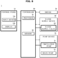
- FIG. 8 is a control block diagram of a washing machine according to an embodiment.
- the washing machine 1 may include the control panel 14 for interacting with a user, the driver 50 for rotating the drum 30, the water supply device 60 for supplying water to the tub 20, the pump device 70 for discharging water accommodated in the tub 20 to the outside, and the controller 90 for controlling various components of the washing machine 1.
- the control panel 14 may include the input device 14a and the display 14b, and operate based on a control signal from the controller 90.
- the driver 50 may rotate the drum 30.
- the driver 50 may include diving circuitry for supplying driving current to the driving motor 51, and the driving circuitry may supply driving current to the driving motor 51 in response to a driving signal from the controller 90.
- the driver 50 may include rectifier circuitry for rectifying alternating current power from an external power source, direct current link circuitry for removing ripples of the rectified power and outputting direct current power, inverter circuitry for converting the direct current power into sinusoidal driving power and outputting driving current to the driving motor 51, a current sensor for measuring the driving current that is supplied to the driving motor 51, and a gate driver for turning on/off a switching device included in the inverter circuitry based on a driving signal from the controller 90.
- rectifier circuitry for rectifying alternating current power from an external power source
- direct current link circuitry for removing ripples of the rectified power and outputting direct current power
- inverter circuitry for converting the direct current power into sinusoidal driving power and outputting driving current to the driving motor 51
- a current sensor for measuring the driving current that is supplied to the driving motor 51
- a gate driver for turning on/off a switching device included in the inverter circuitry based on a driving signal from the controller 90.
- the water supply device 60 may provide water supplied from an external power source to the tub 20 based on a control signal from the controller 90.
- the water supply device 60 may include the water supply valve 62 provided in the water supply guide 61 to supply water to the water supply port 106.
- the water supply valve 62 may be an electronic valve of which an opening rate is adjusted, or an on-off valve of which an opening rate is not adjusted.
- Water supplied by the water supply device 60 may flow into the detergent supply device 100 through the water supply port 106, a part of water in the space between the case cover 105 and the case guide 107 may be discharged to the detergent accommodating portion 113 through the water supply hole 108, and another part of the water in the space between the case cover 105 and the case guide 107 may be discharged to the filter installing portion 116 through the washing hole 109.
- the pump device 70 may include the circulation pump 71 and the drain pump 72. Water pumped by the circulation pump 71 of the pump device 70 may flow into the tub 20 via the detergent supply device 100.
- Water pumped by the drain pump 72 of the pump device 70 of the washing machine 1 may be discharged to the outside without passing through the detergent supply device 100.
- the pump device 70 may be driven by a driving signal from the controller 90.
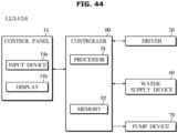
- the controller 90 may include at least one memory 92 and at least one processor 91 for performing the above-described operations and operations which will be described below.
- the controller 90 may include at least one memory 92 that stores data in the form of an algorithm and/or program for controlling operations of components in the washing machine 1, and at least one processor 91 that performs the above-described operations and operations which will be described below by using the data stored in the at least one memory 92.
- the memory 92 and the processor 91 may be implemented with separate chips.
- the processor 91 may include one, two, or more processor chips or one, two, or more processing cores.
- the memory 92 may include one, two, or more memory chips or one, two, or more memory blocks. Also, the memory 92 and the processor 91 may be implemented with a single chip.
- the controller 90 may process a user input received through the input device 14a, and control various components (for example, the driver 50, the water supply device 60, the display 14b, and the pump device 70) of the washing machine 1 based on the processed result of the user input.
- various components for example, the driver 50, the water supply device 60, the display 14b, and the pump device 70
- the controller 90 may perform a washing operation, a rinsing operation, and a dehydrating operation, sequentially, according to a user input received through the input device 14a.
- the controller 90 may control the water supply device 60 to provide water supplied from an external power source to the tub 20.
- the controller 90 may open the water supply valve 62 to supply water.
- the controller 90 may close the water supply valve 62 based on satisfaction of a water supply termination condition.
- the controller 90 may fully open the electronic valve to supply water.
- Water supplied to the detergent supply device 100 through the water supply port 106 during water supply may flow into the water supply hole 108 and the washing hole 109.
- the filter 120 may be washed.
- the controller 90 may perform a circulation operation during a washing operation and/or a rinsing operation.
- the controller 90 may drive the circulation pump 71 of the pump device 70.
- water pumped by the circulation pump 71 of the pump device 70 may flow into the tub 20 via the detergent supply device 100. According to a circulation operation in which water from which foreign materials have been removed flows into the tub 20, more efficient washing may be performed.
- foreign materials may be collected in the filter 120 during a circulation operation.
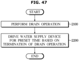
- the washing machine 1 may drive the water supply device 60 for a preset time during a drain operation.
- the controller 90 may open the water supply valve 62 for the preset time during the drain operation.
- the controller 90 may partially open the electronic valve for the preset time during a drain operation. That is, the controller 90 may open the water supply valve 62 by a first opening rate during a water supply operation, and open the water supply valve 62 by a second opening rate for the preset time during a drain operation, wherein the first opening rate may be greater than the second opening rate.
- an amount of water flowing into the tub 20 may be reduced.
- the washing machine 1 may receive a user input for cleaning the filter 120.
- the user input for cleaning the filter 120 may be received through the input device 14a of the control panel 14, or from an external device (for example, a user terminal) through a communication module of the washing machine 1.
- the controller 90 of the washing machine 1 may open the water supply valve 62 for a preset time based on reception of a user input for cleaning the filter 120. At this time, the water supply valve 62 may partially open.
- the user's convenience may be improved.
- FIG. 9 shows a cross section of a washing machine according to an embodiment.
- FIG. 10 is an exploded view of a detergent supply device shown in FIG. 9 .
- FIG. 11 shows a drawer shown in FIG. 9 .
- FIG. 12 shows a flow of water that is filtered by passing through a filter, in a cross section of the detergent supply device shown in FIG. 10 .
- FIG. 13 shows a flow of water that washes the filter, in the cross section of the detergent supply device shown in FIG. 10 .
- a washing machine 2 according to an embodiment will be described with reference to FIGS. 9 to 13 .
- the same components as those of the washing machine 1 shown in FIGS. 1 to 9 are assigned like reference numerals and detailed descriptions thereof will be omitted.
- the washing machine 2 may include a detergent supply device 200 configured to receive water through the water supply device 60.
- the detergent supply device 200 may be connected to the pump device 70 through the drain guide 82.
- the detergent supply device 200 may be connected to an external guide 84 to discharge water stored in the detergent supply device 200 to outside of the washing machine 2.
- the detergent supply device 200 may include a drawer case 200a configured with a case body 201, the case cover 105, and the case guide 107.
- the case body 201 may include a case inlet 204a and a case outlet 204b.
- the case inlet 204a may be connected to the drain guide 82. Water guided along the drain guide 82 may flow into the drawer case 200a through the case inlet 204a.
- the case inlet 204a may be connected to the filter inlet 124. The water flowed into the drawer case 200a through the case inlet 204a may flow into the inside of the filter 120 through the filter inlet 124.
- the case outlet 204b may be connected to the external guide 84. Water in the drawer case 200a may be discharged to the external guide 84 through the case outlet 204b.
- the case outlet 204b may communicate with a filter installing portion 216. Water in the filter installing portion 216 may be discharged to outside of the drawer case 200a through the case outlet 204b.
- the detergent supply device 200 may include a drawer 210 that is accommodated in the drawer case 200a.
- the drawer 210 may include a drawer outlet 214 for discharging water and/or a detergent in the detergent accommodating portion 113 to a space between the drawer body 211 and the case body 201.
- the drawer outlet 114 shown in FIG. 4 may communicate with the filter installing portion 116, whereas the drawer outlet 214 shown in FIG. 10 may not communicate with the filter installing portion 216.
- the drawer outlet 214 may be partitioned from the filter installing portion 216.
- the drawer 210 may include the filter installing portion 216 formed to install the filter 120 therein.
- the filter installing portion 216 may be separated from the drawer outlet 214.
- the filter installing portion 216 may be formed to prevent water in the filter installing portion 216 from being discharged to the space between the drawer body 211 and the case body 201.
- the filter installing portion 216 may include a filter inlet accommodating portion 216a in which the filter inlet 124 of the filter 120 is accommodated.
- the filter inlet accommodating portion 216a may be positioned to correspond to the case inlet 204a.
- the filter installing portion 216 may include a drain port 216b connected to the case outlet 204b.
- the drain port 216b may connect the filter installing portion 216 to the case outlet 204b. Water in the filter installing portion 216 may be discharged to the outside of the drawer case 200a through the case outlet 204b via the drain port 216b, without passing through the space between the drawer body 211 and the case body 201.
- the washing machine 2 may filter out, while discharging water in the tub 20 to the outside of the washing machine 2, foreign materials from water that is discharged.
- Water that is discharged from the pump device 70 toward the tub 20 may be guided along the drain guide 82.
- the water guided along the drain guide 82 may flow into the detergent supply device 200 through the case inlet 204a.
- the water flowed through the case inlet 204a may flow into the inside space of the filter 120 through the filter inlet 124 connected to the case inlet 204a. While the water flowed into the inside space of the filter 120 moves to the outside of the filter 120 through the filter portion 122, foreign materials may be filtered out from the water.
- the filter portion 122 may include the filter side 122a that faces the inside of the filter 120. While water passed through the filter inlet 124 moves from the inside of the filter 120 to the outside, foreign materials may be filtered out from the water, and the foreign materials filtered out by passing through the filter portion 122 may be collected on the filter side 122a of the filter portion 122.
- the water which has passed through the filter 120 and from which foreign materials have been filtered out may move to a space between the filter installing portion 216 and the filter 120.
- the water moved to the space between the filter installing portion 216 and the filter 120 may pass through the drain port 216b and the case outlet 204b sequentially and then be discharged from the detergent supply device 200.
- the water discharged through the case outlet 204b may be discharged to the outside of the washing machine 2 through the external guide 84.
- the washing machine 2 because the washing machine 2 according to various embodiments is capable of filtering out foreign materials from water discharged from the tub 20, an amount of foreign materials that are discharged from the washing machine 2, particularly, an amount of foreign materials having fine sizes may be reduced.
- the washing machine 2 may wash the filter 120 while water is supplied to the detergent supply device 200 by the water supply device 60.
- Water supplied by the water supply device 60 may flow into the detergent supply device 200 through the water supply port 106.
- the water flowed into the detergent supply device 200 may be guided by the guide rib 107a in the space between the case cover 105 and the case guide 107.
- a part of the water in the space between the case cover 105 and the case guide 107 may be discharged to the detergent accommodating portion 113 through the water supply hole 108.
- the water discharged to the detergent supply device 200 may be discharged, together with a detergent in the detergent accommodating portion 113, to the space between the drawer body 211 and the case body 201 through the drawer outlet 214.
- the water discharged to the space between the drawer body 211 and the case body 201 may be discharged through the tub port 103.
- the water discharged through the tub port 103 may be guided to the tub 20 through the tub guide 63.
- Another part of the water in the space between the case cover 105 and the case guide 107 may be discharged to the filter installing portion 216 through the washing hole 109.
- the water discharged to the filter installing portion 216 may be discharged toward the filter 120.
- the water discharged through the washing hole 109 may be discharged toward the outer side of the filter 120.
- the water discharged through the washing hole 109 may be discharged to the opposite side of the filter side 122a of the filter 120. Because water is supplied to the side of the filter 120 being opposite to the filter side 122a where foreign materials are collected, foreign materials collected on the filter side 122a may be separated from the filter side 122a.
- Foreign materials collected on the filter side 122a of the filter portion 122, positioned at the upper side of the filter 120 facing the washing hole 109, may move to the lower portion of the filter 120.
- At least a part of foreign materials collected on the filter side 122a of the filter portion 122, positioned at the front, rear, left, or right sides of the filter 120 may move to the lower portion of the filter 120.
- the water washed the filter 120 may move to the space between the filter installing portion 216 and the filter 120.
- the water moved to the space between the filter installing portion 216 and the filter 120 may pass through the drain port 216b and the case outlet 204b sequentially and then be discharged from the detergent supply device 200.
- the water discharged through the case outlet 204b may be discharged to the outside of the washing machine 2 through the external guide 84.
- the washing machine 2 may wash the filter 120 with water supplied through the water supply device 60, thereby extending a life span of the filter 120 and increasing a replacement cycle of the filter 120.
- FIG. 14 is a control block diagram of a washing machine according to an embodiment.
- the washing machine 2 may include the control panel 14 for interacting with a user, the driver 50 for rotating the drum 30, the water supply device 60 for supplying water to the tub 20, the pump device 70 for discharging water accommodated in the tub 20 to the outside, and the controller 90 for controlling various components of the washing machine 1.
- the control panel 14 may include the input device 14a and the display 14b, and operate based on a control signal from the controller 90.
- the controller 90 may open the water supply valve 62 to supply water.
- the controller 90 may close the water supply valve 62 based on satisfaction of a water supply termination condition.
- the controller 90 may fully open the electronic valve to supply water.
- Water supplied to the detergent supply device 200 through the water supply port 106 during water supply may flow into the water supply hole 108 and the washing hole 109.
- the filter 120 may be washed.
- the controller 90 may drive the drain pump 72 of the pump device 70.
- water pumped by the drain pump 72 of the pump device 70 may be discharged to the outside via the detergent supply device 200. According to a drain operation in which water from which foreign materials have been removed is discharged to the outside of the tub 20, environmental pollution may be further prevented.
- the controller 90 may wash the filter side 122a by opening the water supply valve 62 in the state in which an amount of water flowed into the filter 120 of the tub 20 is small during a drain operation.
- the controller 90 may open the water supply valve 62 for the preset time.
- the washing machine 2 may further include a water level sensor (not shown).
- the controller 90 may open the water supply valve 62 for the preset time.
- the controller 90 may open the water supply valve 62 for the preset time.
- foreign materials collected on the filter side 122a may be efficiently removed during a drain operation.
- the washing machine 2 may receive a user input for cleaning the filter 120.
- the user input for cleaning the filter 120 may be received through the input device 14a of the control panel 14, or from an external device (for example, a user terminal) through the communication module of the washing machine 2.
- the controller 90 of the washing machine 2 may open the water supply valve 62 for a preset time. At this time, the water supply valve 62 may partially open.
- the user's convenience may be improved.
- FIG. 15 shows a cross section of a washing machine according to an embodiment.
- FIG. 16 is an exploded view of a detergent supply device shown in FIG. 15 .
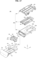
- FIG. 17 shows a drawer shown in FIG. 14 .
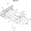
- FIG. 18 shows a state in which a circulation door of the drawer shown in FIG. 17 closes a circulation opening.
- FIG. 19 shows a flow of water that flows into a pump device and then is discharged to a tub, in a cross section of the detergent supply device shown in FIG. 16 .
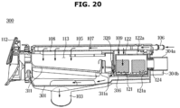
- FIG. 20 shows a flow of water that washes a filter and then is discharged to the tub, in the cross section of the detergent supply device shown in FIG. 16 .
- FIG. 20 shows a flow of water that washes a filter and then is discharged to the tub, in the cross section of the detergent supply device shown in FIG. 16 .
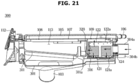
- FIG. 21 shows a flow of water that is supplied from the pump device and then discharged to outside of the washing machine, in the cross section of the detergent supply device shown in FIG. 16 .
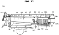
- FIG. 22 shows a flow of water that washes the filter and then is discharged to the outside of the washing machine, in the cross section of the detergent supply device shown in FIG. 16 .
- a washing machine 3 according to an embodiment will be described with reference to FIGS. 15 to 22 .
- the same components as those of the washing machine 2 shown in FIGS. 9 to 13 are assigned like reference numerals and detailed descriptions thereof will be omitted.
- the washing machine 3 may include a detergent supply device 300 configured to receive water through the water supply device 60.
- the detergent supply device 300 may be connected to the pump device 70 through the drain guide 82 and the circulation guide 83.
- the detergent supply device 300 may be connected to the tub guide 63 to discharge water in the detergent supply device 300 to the tub 20.
- the detergent supply device 300 may be connected to the external guide 84 and discharge water in the detergent supply device 300 to outside of the washing machine 3.
- the detergent supply device 300 may include a drawer case 300a configured with a case body 301, the case cover 105, and the case guide 107.
- the case body 301 may include a case inlet 304a and a case outlet 304b.
- the case inlet 304a may include a circulation case inlet 304aa and a drain case inlet 304ab.
- the circulation case inlet 304aa may be connected to the circulation guide 83. Water guided along the circulation guide 83 may flow into the drawer case 300a through the circulation case inlet 304aa.
- the drain case inlet 304ab may be connected to the drain guide 82. Water guided along the drain guide 82 may flow into the drawer case 300a through the drain case inlet 304ab.
- the case inlet 304a may be connected to the filter inlet 124. Water flowed into the drawer case 300a through the case inlet 304a may flow into the filter 120 through the filter inlet 124.
- the case outlet 304b may be connected to the external guide 84. Water in the drawer case 300a may be discharged to the external guide 84 through the case outlet 304b.
- the case outlet 304b may communicate with a filter installing portion 316. Water in the filter installing portion 216 may be discharged to outside of the drawer case 300a through the case outlet 340b.
- the detergent supply device 300 may include a drawer 310 that is accommodated in the drawer case 300a.
- the drawer 310 may include a drawer outlet 314 for discharging water and/or a detergent in the detergent accommodating portion 113 to a space between a drawer body 311 and the case body 301.
- the drawer outlet 314 shown in FIG. 16 may selectively communicate with the filter installing portion 316.
- the drawer 310 may include the filter installing portion 316 formed to install the filter 120 therein.
- the filter installing portion 316 may be selectively partitioned from the drawer outlet 314.
- the filter installing portion 316 may be formed to selectively discharge water in the filter installing portion 316 to the space between the drawer body 311 and the case body 301.
- the filter installing portion 316 may include a filter inlet accommodating portion 316a in which the filter inlet 124 of the filter 120 is accommodated.
- the filter inlet accommodating portion 316a may be positioned to correspond to the case inlet 304a.
- the filter installing portion 316 may include a drain port 316b connected to the case outlet 304b.
- the drain port 316b may connect the filter installing portion 316 to the case outlet 304b. Water in the filter installing portion 316 may be discharged to the outside of the drawer case 300a through the case outlet 304b via the drain port 316b without passing through the space between the drawer body 311 and the case body 301.
- the drawer body 311 may include a drawer hole 311a for communicating the filter installing portion 316 with the space between the drawer body 311 and the case body 301.
- the drawer hole 311a may be opened or closed by a hole opening/closing device 320.
- the detergent supply device 300 may include the hole opening/closing device 320 for opening or closing the drawer hole 311a.
- the hole opening/closing device 320 may include a hole door 321, and a door driver 322 for operating the hole door 321.
- the filter installing portion 316 may selectively communicate with the space between the drawer body 311 and the case body 301.
- the washing machine 3 may filter out, while circulating water in the tub 20, foreign materials from the circulating water. While water in the tub 20 circulates, the hole opening/closing device 320 may open the drawer hole 311a.
- Water discharged from the pump device 70 toward the tub 20 may be guided along the circulation guide 83.
- the water guided along the circulation guide 83 may flow into the detergent supply device 300 through the circulation case inlet 304aa of the case inlet 304a.
- the water flowed through the circulation case inlet 304aa of the case inlet 304a may flow into the inside space of the filter 120 through the filter inlet 124 connected to the case inlet 304a. While the water flowed into the inside space of the filter 120 moves to the outside of the filter 120 through the filter portion 122, foreign materials may be filtered out from the water.
- the filter portion 122 may include the filter side 122a that faces the inside of the filter 120. While water flowed through the filter inlet 124 moves from the inside of the filter 120 to the outside, foreign materials may be filtered out from the water, and the foreign materials filtered out by passing through the filter portion 122 may be collected on the filter side 122a of the filter portion 122.
- the water which has passed through the filter 120 and from which foreign materials have been filtered out may move to the space between the drawer body 311 and the case body 301 from the filter installing portion 316 through the drawer hole 311a.
- the water discharged to the space between the drawer body 311 and the case body 301 may be discharged through the tub port 103.
- the water discharged through the tub port 103 may be guided to the tub 20 through the tub guide 63.
- the washing machine 3 because the washing machine 3 according to various embodiments filters out foreign materials from water circulating through the tub 20, an amount of foreign materials that are discharged from the washing machine 3, particularly, an amount of foreign materials having fine sizes may be reduced.
- the washing machine 3 may wash the filter 120 while water is supplied to the detergent supply device 300 by the water supply device 60, and discharge water washed the filter 120 to the tub 20.
- the hole opening/closing device 320 may open the drawer hole 311a.
- Water supplied by the water supply device 60 may flow into the detergent supply device 300 through the water supply port 106.
- the water flowed into the detergent supply device 300 may be guided by the guide rib 107a in the space between the case cover 105 and the case guide 107.
- a part of the water in the space between the case cover 105 and the case guide 107 may be discharged to the detergent accommodating portion 113 through the water supply hole 108.
- the water discharged to the detergent accommodating portion 113 may be discharged, together with a detergent in the detergent accommodating portion 113, to the space between the drawer body 311 and the case body 301 through the drawer outlet 314.
- the water discharged to the space between the drawer body 311 and the case body 301 may be discharged through the tub port 103.
- the water discharged through the tub port 103 may be guided to the tub 20 through the tub guide 63.
- Another part of the water in the space between the case cover 105 and the case guide 107 may be discharged to the filter installing portion 316 through the washing hole 109.
- the water discharged to the filter installing portion 316 may be discharged toward the filter 120.
- the water discharged through the washing hole 109 may be discharged toward the outer side of the filter 120.
- the water discharged through the washing hole 109 may be discharged to the opposite side of the filter side 122a of the filter 120. Because water is supplied to the side of the filter 120 being opposite to the filter side 122a where foreign materials are collected, foreign materials collected on the filter side 122a may be separated from the filter side 122a.
- Foreign materials collected on the filter side 122a of the filter portion 122, positioned at the upper side of the filter 120 facing the washing hole 109, may move to the lower portion of the filter 120.
- At least a part of foreign materials collected on the filter side 122a of the filter portion 122, positioned at the front, rear, left, or right sides of the filter 120, may move to the lower portion of the filter 120.
- the water washed the filter 120 may move to the space between the drawer body 311 and the case body 301 from the filter installing portion 316 through the drawer hole 311a.
- the water discharged to the space between the drawer body 311 and the case bod 301 may be discharged through the tub port 103.
- the water discharged through the tub port 103 may be guided to the tub 20 through the tub guide 63.
- the washing machine 3 may wash the filter 120 with water supplied through the water supply device 60, thereby extending a life span of the filter 120 and increasing a replacement cycle of the filter 120.
- the washing machine 3 may filter foreign materials out from the water that is discharged. While water in tub 20 is discharged to the outside of the washing machine 3, the hole opening/closing device 320 may close the drawer hole 311a.
- Water discharged from the pump device 70 toward the tub 20 may be guided along the drain guide 82.
- the water guided along the drain guide 82 may flow into the detergent supply device 300 through the drain case inlet 304ab of the case inlet 304a.
- the water flowed through the drain case inlet 304ab of the case inlet 304a may flow into the inside space of the filter 120 through the filter inlet 124 connected to the case inlet 304a. While the water flowed into the inside space of the filter 120 moves to the outside of the filter 120 through the filter portion 122, foreign materials may be filtered out from the water.
- the filter portion 122 may include the filter side 122a that faces the inside of the filter 120. While water flowed through the filter inlet 124 moves from the inside of the filter 120 to the outside, foreign materials may be filtered out from the water, and the foreign materials filtered out by passing through the filter portion 122 may be collected on the filter side 122a of the filter portion 122.
- the water which has passed through the filter 120 and from which foreign materials have been filtered out may be discharged to the space between the filter installing portion 316 and the filter 120.
- the water moved to the space between the filter installing portion 316 and the filter 120 may pass the drain port 316b and the case outlet 304b sequentially and then be discharged from the detergent supply device 300.
- the water discharged through the case outlet 304b may be discharged to the outside of the washing machine 3 through the external guide 84.
- the washing machine 3 because the washing machine 3 according to various embodiments filters out foreign materials from water that is discharged from the tub 20, an amount of foreign materials that are discharged from the washing machine 3, particularly, an amount of foreign materials having fine sizes, may be reduced.
- the washing machine 3 may wash the filter 120 while water is supplied to the detergent supply device 300 by the water supply device 60, and discharge water washed the filter 120 to the outside of the washing machine 3.
- the hole opening/closing device 320 may close the drawer hole 311a.
- Water supplied by the water supply device 60 may flow into the detergent supply device 300 through the water supply port 106.
- the water flowed into the detergent supply device 300 may be guided by the guide rib 107a in the space between the case cover 105 and the case guide 107.
- a part of the water in the space between the case cover 105 and the case guide 107 may be discharged to the detergent accommodating portion 113 through the water supply hole 108.
- the water discharged to the detergent accommodating portion 113 may be discharged, together with a detergent in the detergent accommodating portion 113, to the space between the drawer body 311 and the case body 301 through the drawer outlet 314.
- the water discharged to the space between the drawer body 311 and the case body 301 may be discharged through the tub port 103.
- the water discharged through the tub port 103 may be guided to the tub 20 through the tub guide 63.
- Another part of the water in the space between the case cover 105 and the case guide 107 may be discharged to the filter installing portion 316 through the washing hole 109.
- the water discharged to the filter installing portion 316 may be discharged toward the filter 120.
- the water discharged through the washing hole 109 may be discharged toward the outer side of the filter 120.
- the water discharged through the washing hole 109 may be discharged to the opposite side of the filter side 122a of the filter 120. Because water is supplied to the side of the filter 120 being opposite to the filter side 122a where foreign materials are collected, foreign materials collected on the filter side 122a may be separated from the filter side 122a.
- Foreign materials collected on the filter side 122a of the filter portion 122, positioned at the upper side of the filter 120 facing the washing hole 109, may move to the lower portion of the filter 120.
- At least a part of foreign materials collected on the filter side 122a of the filter portion 122, positioned at the front, rear, left, or right sides of the filter 120 may move to the lower portion of the filter 120.
- the water washed the filter 120 may move to the space between the filter installing portion 316 and the filter 120.
- the water moved to the space between the filter installing portion 316 and the filter 120 may pass through the drain port 316b and the case outlet 304b sequentially and then be discharged from the detergent supply device 300.
- the water discharged through the case outlet 304b may be discharged to the outside of the washing machine 3 through the external guide 84.
- the washing machine 3 may wash the filter 120 with water supplied through the water supply device 60, thereby extending a life span of the filter 120 and increasing a replacement cycle of the filter 120.
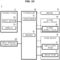
- FIG. 23 is a control block diagram of a washing machine according to an embodiment.
- the washing machine 3 may include the control panel 14 for interacting with a user, the driver 50 for rotating the drum 30, the water supply device 60 for supplying water to the tub 20, the pump device 70 for discharging water accommodated in the tub 20 to the outside, and the controller 90 for controlling various components of the washing machine 1.
- the control panel 14 may include the input device 14a and the display 14b, and operate based on a control signal from the controller 90.
- the washing machine 3 may further include the hole opening/closing device 320.
- the hole opening/closing device 320 may include the hole door 321, and the door driver 322 for operating the hole door 321. According to the hole opening/closing device 320 opening/closing the drawer hole 311a, the filter installing portion 316 may selectively communicate with the space between the drawer body 311 and the case body 301.
- the controller 90 may process a user input received through the input device 14a, and control various components (for example, the driver 50, the water supply device 60, the display 14b, the pump device 70 and/or the hole opening/closing device 320) of the washing machine 3 based on the processed result of the user input.
- various components for example, the driver 50, the water supply device 60, the display 14b, the pump device 70 and/or the hole opening/closing device 320
- the controller 90 may drive the circulation pump 71 of the pump device 70 for a circulation operation.
- water pumped by the circulation pump 71 of the pump device 70 of the washing machine 3 may flow into the tub 20 via the detergent supply device 300. According to a circulation operation in which water from which foreign materials have been removed flows into the tub 20, more efficient washing may be performed.
- the controller 90 may drive the drain pump 72 of the pump device 70.
- water pumped by the drain pump 72 of the pump device 70 of the washing machine 3 may be to the outside via the detergent supply device 300. According to a drain operation in which water from which foreign materials have been removed is discharged to the outside of the tub 20, environmental pollution may be further prevented.
- foreign materials may be collected in the filter 120 during a drain operation and a circulation operation.
- the washing machine 3 may drive the water supply device 60 for a preset time during a drain operation.
- the controller 90 may open the water supply valve 62 for the preset time during a drain operation.
- the controller 90 may partially open the electronic valve for the preset time during a drain operation. That is, the controller 90 may open the water supply valve 62 by a first opening rate during a water supply operation, and open the water supply valve 62 by a second opening rate for the preset time during a drain operation, wherein the first opening rate may be greater than the second opening rate.
- an amount of water that flows into the tub 20 may be reduced.
- the controller 90 may wash the filter side 122a by opening the water supply valve 62 in the state in which an amount of water flowed into the filter 120 of the tub 20 is small during a drain operation.
- the controller 90 may open the water supply valve 62 for the preset time.
- the washing machine 3 may further include a water level sensor (not shown).
- the controller 90 may open the water supply valve 62 for the preset time.
- the controller 90 may open the water supply valve 62 for the preset time.
- foreign materials collected on the filter side 122a may be efficiently removed during a drain operation.
- the washing machine 3 may open the drawer hole 311a during a circulation operation (3200).
- the controller 90 of the washing machine 3 may control the hole opening/closing device 320 to open the drawer hole 311a during a circulation operation.
- the hole opening/closing device 320 may open the hole door 321 based on a control signal from the controller 90 during the circulation operation.
- water passed through the filter 120 may again flow into the tub 20 through the drawer hole 311a.
- water passed through the filter 12 may be guided to again flow into the tub 20.
- the hole door 321 is positioned at an opposite side of a side to which water flows, a major part of water flowed into the inside space of the filter 120 by the pump device 70 may circulate to the tub 20 through the drawer hole 311a by pressure.
- the washing machine 3 may further include a drain valve (not shown) for opening/closing the case outlet 304b or opening/closing the external guide 84.
- the controller 90 may close the drain valve during a circulation operation.
- an amount of water that is discharged to the outside of the washing machine 3 during a circulation operation may be reduced.
- the washing machine 3 may close the drawer hole 311a during a drain operation.
- the controller 90 of the washing machine 3 may control the hole opening/closing device 320 to close the drawer hole 311a during a drain operation.
- the hole opening/closing device 320 may close the hole door 321 based on a control signal from the controller 90 during the drain operation.
- water passed through the filter 120 may be discharged to the outside through the case outlet 304b.
- water passed through the filter 120 may be guided to be discharged to the outside of the washing machine 3.
- the washing machine 3 may receive a user input for cleaning the filter 120.
- the user input for cleaning the filter 120 may be received through the input device 14a of the control panel 14, or from an external device (for example, a user terminal) through the communication module of the washing machine 2.
- FIG. 24 shows a cross section of a washing machine according to an embodiment.
- FIG. 25 is an exploded view of a detergent supply device shown in FIG. 24 .
- FIG. 26 shows a flow of water that is supplied to a detergent accommodating portion, in a cross section of the detergent supply device shown in FIG. 25 .
- FIG. 27 shows a flow of water that is filtered by passing through a filter, in the cross section of the detergent supply device shown in FIG. 25 .
- FIG. 28 shows a flow of water that washes the filter, in the cross section of the detergent supply device shown in FIG. 25 .
- a washing machine 4 according to an embodiment will be described with reference to FIGS. 24 to 28 .
- the same components as those of the washing machine 1 shown in FIGS. 1 to 7 are assigned like reference numerals and detailed descriptions thereof will be omitted.
- the washing machine 4 may include a detergent supply device 400 configured to receive water through a water supply device 60a.
- the detergent supply device 400 may be connected to the pump device 70 through the circulation guide 83.
- the detergent supply device 400 may be connected to the tub guide 63 to discharge water of the detergent supply device 400 to the tub 20.
- the detergent supply device 400 may include a drawer case 400a configured with the case body 101, a case cover 405, and a case guide 407.
- the case body 101 may have the same configuration as the case body 101 of the detergent supply device 100 shown in FIG. 4 .
- the detergent supply device 400 may include the drawer 110 and the filter 120 having the same configurations as the drawer 110 and the filter 120 of the detergent supply device 100 shown in FIG. 4 .
- the case cover 405 may include a first water supply port 406a and a second water supply port 406b.
- the first water supply port 406a may be formed through which water to be supplied to the detergent accommodating portion 113 flows into the drawer case 400a.
- a plurality of first water supply ports 406a for hot water and cold water may be provided.
- the second water supply port 406b may be formed through which water to be supplied to the filter 120 flows into the drawer case 400a.
- the washing machine 4 may include a first water supply guide 61a connected to the first water supply port 406a.
- a first water supply valve 62a may be provided in the first water supply guide 61a.
- the first water supply valve 62a may allow or block supply of water through the first water supply guide 61a.
- the washing machine 4 may include a second water supply guide 61b connected to the second water supply port 406b.
- a second water supply valve 62b may be provided in the second water supply guide 61b.
- the second water supply valve 62b may allow or block supply of water through the second water supply guide 61b.
- the case guide 407 may include the water supply hole 108 that communicates with the detergent accommodating portion 113, and the washing hole 109 that communicates with the filter installing portion 116.
- the case guide 407 may include a partition 407b for partitioning a first flow path P1 along which water to be supplied to the detergent accommodating portion 113 through the water supply hole 108 flows, from a second flow path P2 along which water to be supplied to the filter installing portion through the washing hole 109 flows.
- the partition 407b may prevent water provided through the first water supply port 406a from being supplied to the filter installing portion 116 through the washing hole 109.
- the partition 407b may prevent water provided through the second water supply port 406b from being supplied to the detergent accommodating portion 113 through the water supply hole 108.
- the washing machine 4 may supply no water to the filter 120 while supplying water to the detergent accommodating portion 113.
- the first water supply valve 62a may allow supply of water to the detergent supply device 400 through the first water supply guide 61a
- the second water supply valve 62b may block supply of water to the detergent supply device 400 through the second water supply guide 61b.
- Water supplied through the first water supply guide 61a may flow into the detergent supply device 400 through the first water supply port 406a. Water flowed into the space between the case cover 405 and the case guide 407 may be guided to the water supply hole 108 along the first flow path P1 and then discharged to the detergent accommodating portion 113. The water discharged to the detergent accommodating portion 113 may be discharged, together with a detergent in the detergent accommodating portion 113, to the space between the drawer body 111 and the case body 101 through the drawer outlet 114. The water discharged to the space between the drawer body 111 and the case body 101 may be discharged through the tub port 103. The water discharged through the tub port 103 may be guided to the tub 20 through the tub guide 63.
- the washing machine 4 may filter out, while circulating water in the tub 20, foreign materials from the circulating water.
- Water discharged toward the tub 20 from the pump device 70 may be guided along the circulation guide 83.
- the water guided along the circulation guide 83 may flow into the detergent supply device 400 through the case inlet 104.
- Water flowed through the case inlet 104 may flow into the inside space of the filter 120 through the filter inlet 124 connected to the case inlet 104. While the water flowed into the inside space of the filter 120 moves to the outside of the filter 120 through the filter portion 122, foreign materials may be filtered out from the water.
- the filter portion 122 may include the filter side 122a that faces the inside of the filter 120. While water flowed through the filter inlet 124 moves from the inside of the filter 120 to the outside, foreign materials may be filtered out from the water, and the foreign materials filtered out by passing through the filter portion 122 may be collected on the filter side 122a of the filter portion 122.
- the water which has passed through the filter 120 and from which foreign materials have been filtered out may be discharged to the space between the drawer body 111 and the case body 101 from the filter installing portion 116 through the drawer outlet 114.
- the water discharged to the space between the drawer body 111 and the case body 101 may be discharged through the tub port 103.
- the water discharged through the tub port 103 may be guided to the tub 20 through the tub guide 63.
- the washing machine 4 because the washing machine 4 according to various embodiments filters out foreign materials from water circulating through the tub 20, an amount of foreign materials that are discharged from the washing machine 4, particularly, an amount of foreign materials having fine sizes may be reduced.
- the washing machine 4 may supply no water to the detergent accommodating portion 113 while supplying water to the filter 120.
- the first water supply valve 62a may block supply of water to the detergent supply device 400 through the first water supply guide 61a
- the second water supply valve 62b may allow supply of water to the detergent supply device 400 through the second water supply guide 61b.
- Water supplied through the second water supply guide 61b may flow into the detergent supply device 400 through the second water supply port 406b. Water flowed into the space between the case cover 405 and the case guide 407 may be guided to the washing hole 109 along the second flow path P2 and then discharged to the filter installing portion 116. The water discharged to the filter installing portion 116 may be discharged toward the filter 120. Water discharged through the washing hole 109 may be discharged toward the outer side of the filter 120. The water discharged through the washing hole 109 may be discharged to the opposite side of the filter side 122a of the filter 120.
- the foreign materials collected on the filter side 122a may be separated from the filter side 122a.
- Foreign materials collected on the filter side 122a of the filter portion 122, positioned at the upper side of the filter 120 facing the washing hole 109, may move to the lower portion of the filter 120.
- At least a part of foreign materials collected on the filter side 122a of the filter portion 122, positioned at the front, rear, left, or right sides of the filter 120 may move to the lower portion of the filter 120.
- the water washed the filter 120 may move to the space between the drawer body 111 and the case body 101 from the filter installing portion 116 through the drawer outlet 114.
- the water moved to the space between the drawer body 111 and the case body 101 may be discharged through the tub port 103.
- the water discharged through the tub port 103 may be discharged to the tub 20 through the tub guide 63.
- the washing machine 4 may wash the filter 120 with water supplied through the water supply device 60a, thereby extending a life span of the filter 120 and increasing a replacement cycle of the filter 120. Because the washing machine 4 according to various embodiments supplies no water to the detergent accommodating portion 113 while supplying water to the detergent supply device 400 to wash the filter 120, the washing machine 4 may reduce water consumption.
- FIG. 29 is a control block diagram of a washing machine according to an embodiment.
- the washing machine 4 may include the control panel 14 for interacting with a user, the driver 50 for rotating the drum 30, the water supply device 60 for supplying water to the tub 20, the pump device 70 for discharging water accommodated in the tub 20 to the outside, and the controller 90 for controlling various components of the washing machine 1.
- the control panel 14 may include the input device 14a and the display 14b, and operate based on a control signal from the controller 90.
- the water supply device 60 may provide water supplied from an external water source to the inside of the tub 20 based on a control signal from the controller 90.
- the water supply device 60 may include the first water supply valve 62a provided in the first water supply guide 61a to supply water to the first water supply port 406a, and the second water supply valve 62b provided in the second water supply guide 61b to supply water to the second water supply port 406b.
- the first water supply valve 62a and the second water supply valve 62b may be on-off valves.
- Water supplied through the first water supply guide 61a may flow into the detergent supply device 400 through the first water supply port 406a and be guided to the water supply hole 108.
- Water supplied through the second water supply guide 61b may flow into the detergent supply device 400 through the second water supply port 406b and be guided to the washing hole 109.
- Water pumped by the drain pump 72 of the pump device 70 of the washing machine 4 may be discharged to the outside without passing through the detergent supply device 400.
- the controller 90 of the washing machine 4 may open the first water supply valve 62a to supply water.
- the controller 90 of the washing machine 4 may close the first water supply valve 62a based on satisfaction of a water supply termination condition.
- Water supplied to the detergent supply device 400 through the first water supply port 406a during water supply may flow into the water supply hole 108.
- the controller 90 may drive the circulation pump 71 of the pump device 70 for a circulation operation.
- water pumped by the circulation pump 71 of the pump device 70 may flow into the tub 20 via the detergent supply device 100. According to a circulation operation in which water from which foreign materials have been removed flows into the tub 20, more efficient washing may be performed.
- foreign materials may be collected in the filter 120 during a circulation operation.
- the washing machine 4 may drive the water supply device 60 for a preset time during a drain operation.
- the controller 90 may open the second water supply valve 62b for the preset time during water supply.
- a time for which the first water supply valve 62a opens during water supply may be shorter than a time for which the second water supply valve 62b opens.
- the washing machine 4 may receive a user input for cleaning the filter 120.
- the user input for cleaning the filter 120 may be received through the input device 14a of the control panel 14, or from an external device (for example, a user terminal) through the communication module of the washing machine 4.
- the controller 90 may open the second water supply valve 62b for a preset time based on reception of a user input for cleaning the filter 120.
- the user's convenience may be improved.
- FIG. 30 shows a cross section of a washing machine according to an embodiment.
- FIG. 31 is an exploded view of a detergent supply device shown in FIG. 30 .
- FIG. 32 shows a flow of water that is supplied to a detergent accommodating portion, in a cross section of a detergent supply device shown in FIG. 30 .
- FIG. 33 shows a flow of water that is filtered by passing through a filter, in the cross section of the detergent supply device shown in FIG. 30 .
- FIG. 34 shows a flow of water that washes the filter, in the cross section of the detergent supply device shown in FIG. 30 .
- a washing machine 5 according to an embodiment will be described with reference to FIGS. 30 to 34 .
- the same components as those of the washing machine 2 shown in FIGS. 9 to 13 and the washing machine 4 shown in FIGS. 24 to 28 are assigned like reference numerals and detailed descriptions thereof may be omitted.
- the washing machine 5 may include a detergent supply device 50 configured to receive water through the water supply device 60a.
- the detergent supply device 500 may be connected to the pump device 70 through the drain guide 82.
- the detergent supply device 500 may be connected to the external guide 84 to discharge water in the detergent supply device 500 to outside of the washing machine 5.
- the detergent supply device 500 may include a drawer case 500a configured with the case body 201, the case cover 405, and the case guide 407.
- the detergent supply device 500 may include the case body 201 having the same configuration as the case body 201 of the detergent supply device 200 shown in FIG. 10 .
- the detergent supply device 500 may include the drawer 210 and the filter 120 having the same configurations as the drawer 210 and the filter 120 of the detergent supply device 200 shown in FIG. 10 .
- the detergent supply device 500 may include the case cover 405 and the case guide 407 having the same configurations as the case cover 405 and the case guide 407 shown in FIG. 25 .
- the washing machine 5 may supply no water to the filter 120 while supplying water to the detergent accommodating portion 113.
- the first water supply valve 62a may allow supply of water to the detergent supply device 500 through the first water supply guide 61a
- the second water supply valve 62b may block supply of water to the detergent supply device 500 through the second water supply guide 61b.
- Water supplied through the first water supply guide 61a may flow into the detergent supply device 500 through the first water supply port 406a. Water flowed into the space between the case cover 405 and the case guide 407 may be guided to the water supply hole 108 along the first flow path P1 and then discharged to the detergent accommodating portion 113.
- the water discharged to the detergent accommodating portion 113 may be discharged together with a detergent in the detergent accommodating portion 113 to the space between the drawer body 211 and the case body 201 through the drawer outlet 214.
- the water discharged to the space between the drawer body 211 and the case body 201 may be discharged through the tub port 103.
- the water discharged through the tub port 103 may be guided to the tub 20 through the tub guide 63.
- the washing machine 5 may filter out, while discharging water in the tub 20 to the outside of the washing machine 5, foreign materials from the water that is discharged.
- Water that is discharged from the pump device 70 toward the tub 20 may be guided along the drain guide 82.
- the water guided along the drain guide 82 may flow into the detergent supply device 500 through the case inlet 204a.
- the water flowed through the case inlet 204a may flow into the inside space of the filter 120 through the filter inlet 124 connected to the case inlet 204a. While the water flowed into the inside space of the filter 120 moves to the outside of the filter 120 through the filter portion 122, foreign materials may be filtered out from the water.
- the filter portion 122 may include the filter side 122a that faces the inside of the filter 120. While water passed through the filter inlet 124 moves from the inside of the filter 120 to the outside, foreign materials may be filtered out from the water and the foreign materials filtered out by passing through the filter portion 122 may be collected on the filter side 122a of the filter portion 122.
- the water which has passed through the filter 120 and from which foreign materials have been filtered out may move to the space between the filter installing portion 216 and the filter 120.
- the water moved to the space between the filter installing portion 216 and the filter 120 may pass through the drain port 216b and the case outlet 204b sequentially and then be discharged from the detergent supply device 500.
- the water discharged through the case outlet 204b may be discharged to the outside of the washing machine 5 through the external guide 84.
- the washing machine 5 because the washing machine 5 according to various embodiments is capable of filtering out foreign materials from water discharged from the tub 20, an amount of foreign materials that are discharged from the washing machine 2, particularly, an amount of foreign materials having fine sizes may be reduced.
- the washing machine 5 may supply no water to the detergent accommodating portion 113 while supplying water to the filter 120.
- the first water supply valve 62a may block supply of water to the detergent supply device 500 through the first water supply guide 61a
- the second water supply valve 62b may allow supply of water to the detergent supply device 500 through the second water supply guide 61b.
- Water supplied through the second water supply guide 61b may flow into the detergent supply device 400 through the second water supply port 406b. Water flowed into the space between the case cover 405 and the case guide 407 may be guided to the washing hole 109 along the second flow path P2 and then discharged to the filter installing portion 216. The water discharged to the filter installing portion 216 may be discharged toward the filter 120. The water discharged through the washing hole 109 may be discharged toward the outer side of the filter 120. The water discharged through the washing hole 109 may be discharged to the opposite side of the filter side 122a of the filter 120.
- foreign materials collected on the filter side 122a may be separated from the filter side 122a.
- Foreign materials collected on the filter side 122a of the filter portion 122, positioned at the upper side of the filter 120 facing the washing hole 109 may move to the lower portion of the filter 120.
- At least a part of foreign materials collected on the filter side 122a of the filter portion 122, positioned at the front, rear, left, or right sides of the filter 120 may move to the lower portion of the filter 120.
- the water washed the filter 120 may move to the space between the filter installing portion 216 and the filter 120.
- the water moved to the space between the filter installing portion 216 and the filter 120 may pass through the drain port 216b and the case outlet 204b sequentially and then be discharged from the detergent supply device 500.
- the water discharged through the case outlet 204b may be discharged to the outside of the washing machine 5 through the external guide 84.
- the washing machine 5 may wash the filter 120 with water supplied through the water supply device 60a, thereby extending a life span of the filter 120 and increasing a replacement cycle of the filter 120.
- FIG. 35 is a control block diagram of a washing machine according to an embodiment.
- the washing machine 5 may include the control panel 14 for interacting with a user, the driver 50 for rotating the drum 30, the water supply device 60 for supplying water to the tub 20, the pump device 70 for discharging water accommodated in the tub 20 to the outside, and the controller 90 for controlling various components of the washing machine 1.
- the control panel 14 may include the input device 14a and the display 14b, and operate based on a control signal from the controller 90.
- the water supply device 60 may provide water supplied from an external water source to the inside of the tub 20 based on a control signal from the controller 90.
- the water supply device 60 may include the first water supply valve 62a provided in the first water supply guide 61a to supply water to the first water supply port 406a, and the second water supply valve 62b provided in the second water supply guide 61b to supply water to the second water supply port 406b.
- the first water supply valve 62a and the second water supply valve 62b may be on-off valves.
- Water supplied through the first water supply guide 61a may flow into the detergent supply device 500 through the first water supply port 406a and be guided to the water supply hole 108.
- Water supplied through the second water supply guide 61b may flow into the detergent supply device 500 through the second water supply port 406b and be guided to the washing hole 109.
- the controller 90 of the washing machine 5 may open the first water supply valve 62a to supply water.
- the controller 90 of the washing machine 5 may close the first water supply valve 62a based on satisfaction of a water supply termination condition.
- Water supplied to the detergent supply device 500 through the first water supply port 406a during water supply may flow into the water supply hole 108.
- the controller 90 of the washing machine 5 may open the second water supply valve 62b for a preset time during water supply.
- a time for which the first water supply valve 62a opens during water supply may be shorter than a time for which the second water supply valve 62b opens.
- the controller 90 may drive the drain pump 72 of the pump device 70.
- water pumped by the drain pump 72 of the pump device 70 may be discharged to the outside via the detergent supply device 500. According to a drain operation in which water from which foreign materials have been removed is discharged to the outside of the tub 20, environmental pollution may be prevented.
- the controller 90 of the washing machine 5 may wash the filter side 122a by opening the second water supply valve 62b in the state in which an amount of water flowed into the filter 120 of the tub 20 is small during a drain operation.
- the controller 90 may open the second water supply valve 62b for a preset time.
- the washing machine 5 may further include a water level sensor.
- the controller 90 of the washing machine 5 may open the second water supply valve 62b for the preset time.
- the controller 90 of the washing machine 5 may open the second water supply valve 62b for the preset time.
- foreign materials collected on the filter side 122a may be efficiently removed during a drain operation.
- FIG. 36 shows a cross section of a washing machine according to an embodiment.
- FIG. 37 is an exploded view of a detergent supply device shown in FIG. 36 .
- FIG. 38 shows a flow of water that is supplied to a detergent accommodating portion, in a cross section of the detergent supply device shown in FIG. 37 .
- FIG. 39 shows a flow of water that is supplied from a pump device and then discharged to a tub, in the cross section of the detergent supply device shown in FIG. 37 .
- FIG. 40 shows a flow of water that washes a filter and then is discharged to the tub, in the cross section of the detergent supply device shown in FIG. 37 .
- FIG. 38 shows a flow of water that is supplied to a detergent accommodating portion, in a cross section of the detergent supply device shown in FIG. 37 .
- FIG. 39 shows a flow of water that is supplied from a pump device and then discharged to a tub, in the cross section of the detergent supply device shown in FIG. 37 .
- FIG. 40 shows
- FIG. 41 shows a flow of water that is supplied from the pump device and then is discharged to outside of the washing machine, in the cross section of the detergent supply device shown in FIG. 37 .
- FIG. 42 shows a flow of water that washes the filter and then is discharged to the outside of the washing machine, in the cross section of the detergent supply device shown in FIG. 37 .
- a washing machine 6 will be described with reference to FIGS. 36 to 42 .
- the same components as those of the washing machine 3 shown in FIGS. 15 to 22 and the washing machine 4 shown in FIGS. 24 to 28 are assigned like reference numerals and detailed descriptions thereof will be omitted.
- the washing machine 6 may include a detergent supply device 600 configured to receive water through the water supply device 60a.
- the detergent supply device 600 may be connected to the pump device 70 through the drain guide 82 and the circulation guide 83.
- the detergent supply device 600 may be connected to the tub guide 63 to discharge water in the detergent supply device 600 to the tub 20.
- the detergent supply device 600 may be connected to the external guide 84 to discharge water in the detergent supply device 600 to outside of the washing machine 6.
- the detergent supply device 600 may include a drawer case 600a configured with the case body 301, the case cover 405, and the case guide 407.
- the detergent supply device 600 may include the case body 301 having the same configuration as the case body 301 of the detergent supply device 300 shown in FIG. 16 .
- the detergent supply device 600 may include the drawer 310 and the filter 120 having the same configurations as the drawer 310 and the filter 120 of the detergent supply device 300 shown in FIG. 16 .
- the detergent supply device 600 may include the case cover 405 and the case guide 407 having the same configurations as the case cover 405 and the case guide 407 shown in FIG. 25 .
- the washing machine 6 may supply no water to the filter 120 while supplying water to the detergent accommodating portion 113.
- the first water supply valve 62a may allow supply of water to the detergent supply device 600 through the first water supply guide 61a
- the second water supply valve 62b may block supply of water to the detergent supply device 400 through the second water supply guide 61b.
- the hole opening/closing device 320 may open or close the drawer hole 311a.
- Water supplied through the first water supply guide 61a may flow into the detergent supply device 600 through the first water supply port 406a. Water flowed into the space between the case cover 405 and the case guide 407 may be guided to the water supply hole 108 along the first flow path P1 and then discharged to the detergent accommodating portion 113.
- the water discharged to the detergent accommodating portion 113 may be discharged together with a detergent in the detergent accommodating portion 113 to the space between the drawer body 311 and the case body 301 through the drawer outlet 314.
- the water discharged to the space between the drawer body 311 and the case body 301 may be discharged through the tub port 103.
- the water discharged through the tub port 103 may be guided to the tub 20 through the tub guide 63.
- the washing machine 6 may filter out, while circulating water in the tub 20, foreign materials from the circulating water. While water in the tub 20 circulates, the hole opening/closing device 320 may open the drawer hole 311a.
- Water discharged from the pump device 70 toward the tub 20 may be guided along the circulation guide 83.
- the water guided along the circulation guide 83 may flow into the detergent supply device 600 through the circulation case inlet 304aa of the case inlet 304a.
- the water flowed through the circulation case inlet 304aa of the case inlet 304a may flow into the inside space of the filter 120 through the filter inlet 124 connected to the case inlet 304a. While the water flowed into the inside space of the filter 120 moves to the outside of the filter 120 through the filter portion 122, foreign materials may be filtered out from the water.
- the filter portion 122 may include the filter side 122a that faces the inside of the filter 120. While water passed through the filter inlet 124 moves from the inside of the filter 120 to the outside, foreign materials may be filtered out from the water and the foreign materials filtered out by passing through the filter portion 122 may be collected on the filter side 122a of the filter portion 122.
- the water which has passed through the filter 120 and from which foreign materials have been filtered out may move to the space between the drawer body 311 and the case body 301 from the filter installing portion 316 through the drawer hole 311a.
- the water discharged to the space between the drawer body 311 and the case body 301 may be discharged through the tub port 103.
- the water discharged through the tub port 103 may be guided to the tub 20 through the tub guide 63.
- the washing machine 6 because the washing machine 6 according to various embodiments filters out foreign materials from water circulating through the tub 20, an amount of foreign materials that are discharged from the washing machine 6, particularly, an amount of foreign materials having fine sizes may be reduced.
- the washing machine 6 may supply no water to the detergent accommodating portion 113 while supplying water to the filter 120.
- the first water supply valve 62a may block supply of water to the detergent supply device 600 through the first water supply guide 61a
- the second water supply valve 62b may allow supply of water to the detergent supply device 600 through the second water supply guide 61b.
- the hole opening/closing device 320 may open the drawer hole 311a.
- Water supplied through the second water supply guide 61b may flow into the detergent supply device 600 through the second water supply port 406b. Water flowed into the space between the case cover 405 and the case guide 407 may be guided to the washing hole 109 along the second flow path P2 and then discharged to the filter installing portion 116. The water discharged to the filter installing portion 116 may be discharged toward the filter 120. Water discharged through the washing hole 109 may be discharged toward the outer side of the filter 120. The water discharged through the washing hole 109 may be discharged to the opposite side of the filter side 122a of the filter 120.
- the foreign materials collected on the filter side 122a may be separated from the filter side 122a.
- Foreign materials collected on the filter side 122a of the filter portion 122, positioned at the upper side of the filter 120 facing the washing hole 109 may move to the lower portion of the filter 120.
- At least a part of foreign materials collected on the filter side 122a of the filter portion 122, positioned at the front, rear, left, or right sides of the filter 120 may move to the lower portion of the filter 120.
- the water washed the filter 120 may move to the space between the drawer body 311 and the case body 301 from the filter installing portion 316 through the drawer hole 311a.
- the water moved to the space between the drawer body 311 and the case body 301 may be discharged through the tub port 103.
- the water discharged through the tub port 103 may be discharged to the tub 20 through the tub guide 63.
- the washing machine 6 may wash the filter 120 with water supplied through the water supply device 60a, thereby extending a life span of the filter 120 and increasing a replacement cycle of the filter 120. Because the washing machine 6 according to various embodiments supplies no water to the detergent accommodating portion 113 while supplying water to the detergent supply device 400 to wash the filter 120, the washing machine 6 may reduce water consumption.
- the washing machine 6 may filter out, while discharging water in the tub 20 to the outside of the washing machine 6, foreign materials from water that is discharged. While water in the tub 20 is discharged to the outside of the washing machine 6, the hole opening/closing device 320 may close the drawer hole 311a.
- Water that is discharged from the pump device 70 toward the tub 20 may be guided along the drain guide 82.
- the water guided along the drain guide 82 may flow into the detergent supply device 600 through the drain case inlet 304ab of the case inlet 304a.
- the water flowed through the drain case inlet 304ab of the case inlet 304a may flow into the inside space of the filter 120 through the filter inlet 124 connected to the case inlet 304a. While the water flowed into the inside space of the filter 120 moves to the outside of the filter 120 through the filter portion 12, foreign materials may be filtered out from the water.
- the filter portion 122 may include the filter side 122a that faces the inside of the filter 120. While water flowed through the filter inlet 124 moves from the inside of the filter 120 to the outside, foreign materials may be filtered out from the water and the foreign materials filtered out by passing through the filter portion 122 may be collected on the filter side 122a of the filter portion 122.
- the water which has passed through the filter 120 and from which foreign materials have been filtered out may be discharged to the space between the filter installing portion 316 and the filter 120.
- the water discharged to the space between the filter installing portion 316 and the filter 120 may pass through the drain port 316b and the case outlet 304b sequentially and then be discharged from the detergent supply device 600.
- the water discharged through the case outlet 304b may be discharged to the outside of the washing machine 6 through the external guide 84.
- the washing machine 6 because the washing machine 6 according to various embodiments is capable of filtering out foreign materials from water discharged from the tub 20, an amount of foreign materials that are discharged from the washing machine 6, particularly, an amount of foreign materials having fine sizes may be reduced.
- the washing machine 6 may supply no water to the detergent accommodating portion 113 while supplying water to the filter 120.
- the first water supply valve 62a may block supply of water to the detergent supply device 400 through the first water supply guide 51a
- the second water supply valve 62b may allow supply of water to the detergent supply device 400 through the second water supply guide 61b.
- the hole opening/closing device 320 may close the drawer hole 311a.
- Water supplied through the second water supply guide 61b may flow into the detergent supply device 600 through the second water supply port 406b. Water flowed into the space between the case cover 405 and the case guide 407 may be guided to the washing hole 109 along the second flow path P2 and then discharged to the filter installing portion 316. The water discharged to the filter installing portion 316 may be discharged toward the filter 120. Water discharged through the washing hole 109 may be discharged toward the outer side of the filter 120. The water discharged through the washing hole 109 may be discharged to the opposite side of the filter side 122a of the filter 120.
- foreign materials collected on the filter side 122a may be separated from the filter side 122a.
- Foreign materials collected on the filter side 122a of the filter portion 122, positioned at the upper side of the filter 120 facing the washing hole 109 may move to the lower portion of the filter 120.
- At least a part of foreign materials collected on the filter side 122a of the filter portion 122, positioned at the front, rear, left, or right sides of the filter 120 may move to the lower portion of the filter 120.
- the water washed the filter 120 may move to the space between the filter installing portion 316 and the filter 120.
- the water moved to the space between the filter installing portion 316 and the filter 120 may pass through the drain port 316b and the case outlet 304b sequentially and then be discharged from the detergent supply device 600.
- the water discharged through the case outlet 304b may be discharged to the outside of the washing machine 6 through the external guide 84.
- the washing machine 6 may wash the filter 120 with water supplied through the water supply device 60a, thereby extending a life span of the filter 120 and increasing a replacement cycle of the filter 120.
- FIG. 43 is a control block diagram of a washing machine according to an embodiment.
- the washing machine 6 may include the control panel 14 for interacting with a user, the driver 50 for rotating the drum 30, the water supply device 60 for supplying water to the tub 20, the pump device 70 for discharging water accommodated in the tub 20 to the outside, and the controller 90 for controlling various components of the washing machine 1.
- the control panel 14 may include the input device 14a and the display 14b, and operate based on a control signal from the controller 90.
- the washing machine 6 may further include the hole opening/closing device 320.
- the hole opening/closing device 320 may include the hole door 321, and the door driver 322 for operating the hole door 321. According to the hole opening/closing device 320 opening/closing the drawer hole 311a, the filter installing portion 316 may selectively communicate with the space between the drawer body 311 and the case body 301.
- the water supply device 60 may provide water supplied from an external water source to the inside of the tub 20 based on a control signal from the controller 90.
- the water supply device 60 may include the first water supply valve 62a provided in the first water supply guide 61a to supply water to the first water supply port 406a, and the second water supply valve 62b provided in the second water supply guide 61b to supply water to the second water supply port 406b.
- the first water supply valve 62a and the second water supply valve 62b may be on-off valves.
- Water supplied through the first water supply guide 61a may flow into the detergent supply device 600 through the first water supply port 406a and be guided into the water supply hole 108.
- Water supplied through the second water supply guide 61b may flow into the detergent supply device 600 through the second water supply port 406b and be guided into the washing hole 109.
- the controller 90 of the washing machine 6 may open the first water supply valve 62a to supply water.
- the controller 90 of the washing machine 6 may close the first water supply valve 62a based on satisfaction of a water supply termination condition.
- Water supplied into the detergent supply device 600 through the first water supply port 406a during water supply may flow into the water supply hole 108.
- the controller 90 of the washing machine 6 may open the second water supply valve 62b for a preset time during water supply.
- a time for which the first water supply valve 62a opens during water supply may be shorter than a time for which the second water supply valve 62b opens.
- the controller 90 may drive the circulation pump 71 of the pump device 70 for a circulation operation.
- water pumped by the circulation pump 71 of the pump device 70 of the washing machine 6 may flow into the tub 20 via the detergent supply device 600. According to a circulation operation in which water from which foreign materials have been removed flows into the tub 20, more efficient washing may be performed.
- the controller 90 may drive the drain pump 72 of the pump device 70.
- water pumped by the drain pump 72 of the pump device 70 of the washing machine 3 may be discharged to the outside via the detergent supply device 300. According to a drain operation in which water from which foreign materials have been removed is discharged to the outside of the tub 20, environmental pollution may be further prevented.
- foreign materials may be collected on the filter 120 during a drain operation and a circulation operation.
- the washing machine 6 may drive the water supply device 60 for the preset time during a drain operation.
- the controller 90 may open the second water supply valve 62b for the preset time during a drain operation.
- the controller 90 may wash the filter side 122a by opening the second water supply valve 62b in the state in which an amount of water flowed into the filter 120 of the tub 20 is small during a drain operation.
- the controller 90 may open the second water supply valve 62b for the preset time.
- the washing machine 2 may further include a water level sensor (not shown).
- the controller 90 may open the second water supply valve 62b for the preset time.
- the controller 90 may open the second water supply valve 62b for the preset time.
- foreign materials collected on the filter side 122a may be efficiently removed during a drain operation.
- the washing machine 6 may open the drawer hole 311a during a circulation operation (3200).
- the controller 90 of the washing machine 6 may control the hole opening/closing device 320 to open the drawer hole 311a during a circulation operation.
- the hole opening/closing device 320 may open the hole door 321 based on a control signal from the controller 90 during the circulation operation.
- water passed through the filter 120 during the circulation operation may again flow into the tub 20 through the drawer hole 311a.
- water passed through the filter 120 during a circulation operation may be guided to again flow into the tub 20.
- the hole door 321 is positioned at an opposite side of a side to which water flows, a major part of water flowed into the inside space of the filter 120 by the pump device 70 may circulate to the tub 20 through the drawer hole 311a by pressure.
- the washing machine 6 may further include a drain valve (not shown) for opening/closing the case outlet 304b or opening/closing the external guide 84.
- the controller 90 may close the drain valve during a circulation operation.
- an amount of water that is discharged to the outside of the washing machine 6 during a circulation operation may be reduced.
- the washing machine 6 may close the drawer hole 311a during a drain operation.
- the controller 90 of the washing machine 6 may control the hole opening/closing device 320 to close the drawer hole 311a during a drain operation.
- the hole opening/closing device 320 may close the hole door 321 based on a control signal from the controller 90 during the drain operation.
- water passed through the filter 120 during the drain operation may be discharged to the outside through the case outlet 304b.
- water passed through the filter 120 may be guided to be discharged to the outside of the washing machine 6.
- the washing machine 6 may receive a user input for cleaning the filter 120.
- the user input for cleaning the filter 120 may be received through the input device 14a of the control panel 14, or from an external device (for example, a user terminal) through a communication module of the washing machine 6.
- the controller 90 may open the second water supply valve 62b for a preset time based on reception of a user input for cleaning the filter 120. At this time, the water supply valve 62 may partially open.
- FIG. 44 is a control block diagram showing a configuration of a washing machine according to various embodiments.
- the washing machine 1, 2, 3, 4, 5, or 6 may include the control panel 14 for interacting with a user, the driver 50 for rotating the drum 30, the water supply device 60 for supplying water to the tub 20, the pump device 70 for discharging water accommodated in the tub 20 to the outside, and the controller 90 for controlling various components of the washing machine 1.
- the control panel 14 may include the input device 14a and the display 14b, and operate based on a control signal from the controller 90.
- the driver 50 may rotate the drum 30.
- the driver 50 may include diving circuitry for supplying driving current to the driving motor 51, and the driving circuitry may supply driving current to the driving motor 51 in response to a driving signal from the controller 90.
- the driver 50 may include rectifier circuitry for rectifying alternating current power from an external power source, direct current link circuitry for removing ripples of the rectified power and outputting direct current power, inverter circuitry for converting the direct current power into sinusoidal driving power and outputting driving current to the driving motor 51, a current sensor for measuring the driving current that is supplied to the driving motor 51, and a gate driver for turning on/off a switching device included in the inverter circuitry based on a driving signal from the controller 90.
- the water supply device 60 may provide water supplied from an external water source to the inside of the tub 20 based on a control signal from the controller 90.
- the water supply device 60 of the washing machine 1, 2, or 3 may include the water supply valve 62 provided in the water supply guide 61 to supply water to the water supply port 106.
- the water supply valve 62 may be an electronic valve of which an opening rate is adjusted, or an on-off valve of which an opening rate is not adjusted.
- Water supplied by the water supply device 60 of the washing machine 1, 2, or 3 may flow into the detergent supply device 100, 200, or 300 through the water supply port 106, a part of water in the space between the case cover 105 and the case guide 107 may be discharged to the detergent accommodating portion 113 through the water supply hole 108, and another part of the water in the space between the case cover 105 and the case guide 107 may be discharged to the filter installing portion 116 through the washing hole 109.
- the water supply device 60 of the washing machine 4, 5, or 6 may include the first water supply valve 62a provided in the first water supply guide 61a to supply water to the first water supply port 406a, and the second water supply valve 62b provided in the second water supply guide 61b to supply water to the second water supply port 406b.
- the first water supply valve 62a and the second water supply valve 62b may be on-off valves.
- Water supplied through the first water supply guide 61a may flow into the detergent supply device 400, 500, or 600 through the first water supply port 406a and be guided into the water supply hole 108.
- Water supplied through the second water supply guide 61b may flow into the detergent supply device 400, 500, or 600 through the second water supply port 406b and be guided into the washing hole 109.
- the pump device 70 may include the circulation pump 71 and the drain pump 72. Water pumped by the circulation pump 71 of the pump device 70 of the washing machine 1, 3, 4, or 6 according to an embodiment may flow into the tub 20 via the detergent supply device 100, 300, 400, or 600.
- Water pumped by the circulation pump 71 of the pump device 70 of the washing machine 2 or 5 may flow into the tub 20 without passing through the detergent supply device 200 or 500.
- Water pumped by the circulation pump 71 of the pump device 70 of the washing machine 2, 3, 5, or 6 may be discharged to the outside via the detergent supply device 200, 300, 500, or 600.
- Water pumped by the drain pump 72 of the pump device 70 of the washing machine 1 or 4 may be discharged to the outside without passing through the detergent supply device 100 or 400.
- the pump device 70 may be driven by a driving signal from the controller 90.
- the controller 90 may include at least one memory 92 and at least one processor 91 for performing the above-described operations and operations which will be described below.
- the controller 90 may include at least one memory 92 that stores data in the form of an algorithm and/or program for controlling operations of components in the washing machine 1, 2, 3, 4, 5, or 6, and at least one processor 91 that performs the above-described operations and operations which will be described below by using the data stored in the at least one memory 92.
- the memory 92 and the processor 91 may be implemented with separate chips.
- the processor 91 may include one, two, or more processor chips or one, two, or more processing cores.
- the memory 92 may include one, two, or more memory chips or one, two, or more memory blocks. Also, the memory 92 and the processor 91 may be implemented with a single chip.
- the controller 90 may process a user input received through the input device 14a, and control various components (for example, the driver 50, the water supply device 60, the display 14b, and the pump device 70) of the washing machine 1, 2, 3, 4, 5, or 6 based on the processed result of the user input.
- various components for example, the driver 50, the water supply device 60, the display 14b, and the pump device 70
- FIG. 45 shows an example of a washing cycle according to an embodiment.
- a washing cycle may include a washing operation 1010, a rinsing operation 1020, and/or a dehydrating operation 1030.
- the washing machine 1, 2, 3, 4, 5, or 6 may perform the washing operation 1010, the rinsing operation 1020, and the dehydrating operation 1030 sequentially according to a user input through the input device 14a.
- laundry may be washed. More specifically, foreign materials attached to the laundry may be separated from the laundry by chemical actions by a detergent and/or mechanical actions such as falling.
- the washing operation 1010 may include laundry measurement 1011 of measuring an amount of laundry, water supply 1012 of supplying water to the tub 20, washing 1013 of rotating the drum 30 at low speed to wash laundry, drainage 1014 of draining water stored in the tub 20, and midway dehydrating 1015 of rotating the drum 30 at high speed to separate water from laundry.
- the controller 90 may control the driver 50 to repeatedly turn on/off the driving motor 51, and measure a load (a weight of the laundry) in the drum 30 based on a counter electromotive force value generated upon turning-off of the driving motor 51.
- the controller 90 may control the water supply device 60 to provide water supplied from an external water supply source to the inside of the tub 20.
- the controller 90 of the washing machine 1, 2, or 3 may open the water supply valve 62 for the water supply 1012.
- the controller 90 of the washing machine 1, 2, or 3 may close the water supply valve 62 based on satisfaction of a water supply termination condition.
- the controller 90 may fully open the electronic valve to supply water.
- Water supplied to the detergent supply device 100, 200, or 300 through the water supply port 106 during the water supply 1012 may flow into the water supply hole 108 and the washing hole 109.
- the filter 120 may be washed.
- the controller 90 of the washing machine 4, 5, or 6 may open the first water supply valve 62a for the water supply 1012.
- the controller 90 of the washing machine 4, 5, or 6 according to an embodiment may close the water supply valve 62a based on satisfaction of a water supply termination condition.
- Water supplied to the water supply device 400, 500, or 600 through the first water supply port 406a during the water supply 1012 may flow into the water supply hole 108.
- the controller 90 of the washing machine 4, 5, or 6 may open the second water supply valve 62b for a preset time during the water supply 1012.
- a time for which the first water supply valve 62a opens during the water supply 1012 may be shorter than a time for which the second water supply valve 62b opens.
- the filter 120 may be washed.
- the controller 90 may control the driver 50 to rotate the driving motor 51 forward (for example, a clockwise direction) or backward (for example, a counterclockwise direction). By rotating the drum 30, laundry may fall from an upper area of the drum 30 to a lower area of the drum 30 and, by the falling, the laundry may be washed.
- a circulation operation of causing water in the tub 20 to pass through the pump device 70 and again enter the tub 20 may be performed.
- the controller 90 may drive the circulation pump 71 of the pump device 70.
- water pumped by the circulation pump 71 of the pump device 70 of the washing machine 1, 3, 4, or 6 may flow into the tub 20 via the detergent supply device 100, 300, 400, or 600. According to a circulation operation in which water from which foreign materials have been removed flows into the tub 20, more efficient washing may be performed.
- foreign materials may be collected in the filter 120 during a circulation operation.
- the controller 90 may drive the drain pump 72 of the pump device 70.
- Water pumped by the drain pump 72 of the pump device 70 of the washing machine 2, 3, 5, or 6 according to an embodiment during the drainage 1014 may be discharged to the outside via the detergent supply device 200, 300, 500, or 600. According to the drainage 1014 in which water from which foreign materials have been removed is discharged to the outside of the tub 20, environmental pollution may be prevented.
- foreign materials may be collected in the filter 120 during the drainage 1014.
- the controller 90 may control the driver 50 to rotate the driving motor 51 at high speed.
- the high-speed rotation of the drum 30 water may be separated from the laundry accommodated in the drum 30 and discharged to the outside of the washing machine 1, 2, 3, 4, 5, or 6.
- the laundry may be rinsed. More specifically, a detergent or foreign materials remaining in the laundry may be washed away by water.
- the rinsing operation 1020 may include water supply 1021 of supplying water to the tub 20, rinsing 1022 of driving the drum 30 to rinse laundry, drainage 1023 of discharging water stored in the tub 20, and midway dehydrating 1024 of driving the drum 30 to separate water from the laundry.
- the water supply 1021, the drainage 1023, and the midway dehydrating 1024 of the rinsing operation 1020 may be the same as the water supply 1012, the drainage 1014, and the midway dehydrating 1015 of the washing operation 1010, respectively. Accordingly, descriptions about the water supply 1021, the drainage 1023, and the midway dehydrating 1024 of the rinsing operation 1020 will be omitted.
- the controller 90 may control the driver 50 to rotate the driving motor 51 forward (for example, the clockwise direction) or backward (for example, the counterclockwise direction). By rotating the drum 30, the laundry may fall from the upper area of the drum 30 to the lower area of the drum 30 and, by the falling, the laundry may be rinsed.
- a circulation operation of causing water in the tub 20 to pass through the pump device 70 and again enter the tub 20 may be performed.
- the controller 90 may drive the circulation pump 71 of the pump device 70.
- water pumped by the circulation pump 71 of the pump device 70 of the washing machine 1, 3, 4, or 6 may flow into the tub 20 via the detergent supply device 100, 300, 400, or 600.
- more efficient rinsing may be performed.
- the laundry By the dehydrating 1030, the laundry may be dehydrated. More specifically, water may be separated from the laundry by a high-speed rotation of the drum 30, and the separated water may be discharged to the outside of the washing machine 1.
- the dehydrating operation 1030 may include final dehydrating 1031 of separating water from laundry by rotating the drum 30 at high speed. Due to the final dehydrating 1031, final midway dehydrating 1024 of the rinsing operation 1020 may be omitted.
- the controller 90 may control the driver 50 to rotate the driving motor 51 at high speed.
- the high-speed rotation of the drum 30 water may be separated from the laundry accommodated in the drum 30 and discharged to the outside of the washing machine 1, 2, 3, 4, 5, or 6.
- a rotation speed of the driving motor 51 may increase in stages.
- a time for which the final dehydrating 1031 is performed may be longer than a time for which the midway dehydrating 1015 or 1024 is performed.
- a drain operation may be performed.
- the controller 90 may operate the drain pump 72 of the pump device 70 during the dehydrating operation 1030.
- the circulation operation may be an operation in which the circulation pump 71 of the pump device 70 operates
- the drain operation may be an operation in which the drain pump 72 of the pump device 70 operates.
- the filter 120 may be washed.
- the life span of the filter 120 may increase, which improves a user's satisfaction.
- an operation of washing the filter 120 may be performed even in the remaining operations except for the water supply 1012 or 1021.
- FIG. 46 is a flowchart illustrating an example of a control method of a washing machine according to various embodiments.
- the washing machine 1, 2, 3, 4, 5, or 6 may perform a circulation operation during a washing cycle (1100).
- the controller 90 may drive the pump device 70 to perform the circulation operation.
- the circulation operation may be performed in a section of the washing operation 1010 or in a section of the rinsing operation 1020, as described above.
- water pumped by the circulation pump 71 of the pump device 70 during a circulation operation may flow into the tub 20 via the detergent supply device 100, 300, 400, or 600. Accordingly, upon completion of the circulation operation, foreign materials filtered out by passing through the filter portion 122 may be collected on the filter side 122a of the filter portion 122.
- the washing machine 1, 3, 4 or 6 may drive the water supply device 60 for a preset time during a drain operation (1200).
- the controller 90 of the washing machine 1 or 3 may open the water supply valve 62 for the preset time during the drain operation.
- the controller 90 may partially open the electronic valve for the preset time during the drain operation. That is, the controller 90 may open the water supply valve 62 by a first opening rate during a water supply operation, and open the water supply valve 62 by a second opening rate for the preset time during a drain operation, wherein the first opening rate may be greater than the second opening rate.
- an amount of water that flows into the tub 20 may be reduced.
- controller 90 of the washing machine 4 or 6 may open the second water supply valve 62b for the preset time during the drain operation.
- the preset time may be set to be shorter than a time of the drain operation, and may be stored in the memory 92.
- the preset time may be set to about 10 seconds, although not limited thereto.
- the washing machine 2 or 5 may also drive the water supply device 60 for the preset time during a drain operation.
- the controller 90 of the washing machine 2, 3, 5, or 6 may wash the filter side 122a by opening the water supply valve 62 in the state in which an amount of water flowed into the filter 120 of the tub 20 is small during a drain operation.
- the controller 90 of the washing machine 2, 3, 5, or 6 may open the water supply valve 62 or 62b for the preset time.
- the washing machine 1, 2, 3, 4, 5, or 6 may further include a water level sensor (not shown).
- the controller 90 of the washing machine 2, 3, 5, or 6 may open the water supply valve 62 or 62b for the preset time.
- the controller 90 of the washing machine 2, 3, 5, or 6 may open the water supply valve 62 or 62b for the preset time.
- foreign materials collected on the filter side 122a may be efficiently removed during a drain operation.
- FIG. 47 is a flowchart illustrating an example of a control method of a washing machine according to various embodiments.
- the washing machine 1, 2, 3, 4, 5, or 6 may perform a drain operation during a washing cycle (2100).
- the controller 90 may drive the pump device 70 to perform the drain operation.
- the drain operation may be performed in a section of a washing operation 1010 or in a section of a rinsing operation 1020.
- water pumped by the drain pump 72 of the pump device 70 during a drain operation may flow into the tub 20 via the detergent supply device 200, 300, 500, or 600. Accordingly, foreign materials filtered out by passing through the filter portion 122 during the drain operation may be collected on the filter side 122a of the filter portion 122.
- the controller 90 of the washing machine 2, 3, 5, or 6 may open the water supply valve 62 or 62b in the state in which an amount of water flowed into the filter 120 is small during a drain operation, thereby washing the filter side 122a.
- the washing machine 2, 3, 5, or 6 may drive the water supply device 60 for a preset time based on termination of the drain operation (2200).
- Termination of the drain operation may be operation termination of the pump device 70.
- the washing machine 2, 3, 5, or 6 may drive the water supply device 60 for the preset time based on operation termination of the pump device 70.
- the controller 90 of the washing machine 2 or 3 may open the water supply valve 62 for the preset time based on termination of the drain operation.
- the controller 90 may partially open the electronic valve for the preset time based on termination of the drain operation. That is, the controller 90 may open the water supply valve 62 by a first opening rate during a water supply operation, and open the water supply valve 62 by a second opening rate for the preset time after a drain operation terminates, wherein the first opening rate may be greater than the second opening rate.
- washing efficiency may be improved.
- an amount of water that flows into the tub 20 after a drain operation terminates may be reduced.
- the controller 90 of the washing machine 5 or 6 may open the second water supply valve 62b for the preset time based on termination of a drain operation.
- washing efficiency may be improved.
- an amount of water that flows into the tub 20 after a drain operation terminates may be reduced.
- the washing machine 1 or 4 may also open the water supply valve 62 or 62b based on termination of a drain operation.
- FIG. 48 is a control block diagram showing a configuration of a washing machine according to various embodiments.
- the washing machine 3 or 6 may further include the hole opening/closing device 320 in addition to components described above with reference to FIG. 44 .
- the hole opening/closing device 320 may include the hole door 321, and the door driver 322 for operating the hole door 321. According to the hole opening/closing device 320 opening/closing the drawer hole 311a, the filter installing portion 316 may selectively communicate with the space between the drawer body 311 and the case body 301.
- FIG. 49 is a flowchart showing an example of a control method of a washing machine according to various embodiments.
- the washing machine 3 or 6 may open the drawer hole 311a during a circulation operation (circulation in 3100) (3200).
- controller 90 of the washing machine 3 or 6 may control the hole opening/closing device 320 to open the drawer hole 311a during the circulation operation (circulation in 3100) (3200).
- the hole opening/closing device 320 may open the hole door 321 based on a control signal from the controller 90 during the circulation operation.
- water passed through the filter 120 during the circulation operation may again flow into the tub 20 through the drawer hole 311a.
- water passed through the filter 120 during the circulation operation may be guided to again flow into the tub 20.
- the hole door 321 is positioned at an opposite side of a side to which water flows, a major part of water flowed into the inside space of the filter 120 by the pump device 70 may circulate to the tub 20 through the drawer hole 311a by pressure.
- washing machine 3 or 6 may further include a drain valve (not shown) for opening/closing the case outlet 304b or opening/closing the external guide 84.
- the controller 90 may close the drain valve during the circulation operation.
- an amount of water that is discharged to the outside of the washing machine 3 or 6 during the circulation operation may be reduced.
- the washing machine 3 or 6 may close the drawer hole 311a during a drain operation (drainage in 3100) (3300).
- the controller 90 of the washing machine 3 or 6 may control the hole opening/closing device 320 to close the drawer hole 311a during a drain operation (drainage in 3100) (3300).
- the hole opening/closing device 320 may close the hole door 321 based on a control signal from the controller 90 during the drain operation.
- water passed through the filter 120 during the drain operation may be discharged to the outside through the case outlet 304b.
- water passed through the filter 120 during the drain operation may be guided to be discharged to the outside of the washing machine 3 or 6.
- the washing machine 3 or 6 may drive the water supply device 60 for a preset time during the drain operation (3400).
- the controller 90 may wash the filter side 122a by opening the water supply valve 62 in the state in which an amount of water flowed into the filter 120 of the tub 20 is small during the drain operation.
- the washing machine 3 or 6 may drive the water supply device 60 for the preset time based on termination of the drain operation (3400).
- the controller 90 may open the water supply valve 62 or 62b for the preset time based on termination of the drain operation.
- all of foreign materials of water that circulates during a circulation operation and foreign materials of water that is discharged during a drain operation may be removed by the filter 120.
- an operation of washing the filter 120 may be performed according to a command from a user.
- the washing machine 1, 2, 3, 4, 5 or 6 may receive a user input for cleaning the filter 120.
- the user input for cleaning the filter 120 may be received through the input device 14a of the control panel 14, or from an external device (for example, a user terminal) through the communication module of the washing machine 1, 2, 3, 4, 5 or 6.
- the controller 90 may open the water supply valve 62 or 62b for a preset time based on reception of a user input for cleaning the filter 120.
- the controller 90 of the washing machine 1, 2, or 3 may open the water supply valve 62 for the preset time based on reception of a user input for cleaning the filter 120. At this time, the water supply valve 62 may partially open.
- the controller 90 of the washing machine 4, 5, or 6 may open the second water supply valve 62b for the preset time based on reception of a user input for cleaning the filter 120. At this time, the water supply valve 62 may partially open.
- the user's convenience may be improved.
Landscapes
- Engineering & Computer Science (AREA)
- Textile Engineering (AREA)
- Chemical & Material Sciences (AREA)
- Chemical Kinetics & Catalysis (AREA)
- Detail Structures Of Washing Machines And Dryers (AREA)
Applications Claiming Priority (4)
| Application Number | Priority Date | Filing Date | Title |
|---|---|---|---|
| KR20220079295 | 2022-06-28 | ||
| KR20220093493 | 2022-07-27 | ||
| KR1020220130087A KR20240002120A (ko) | 2022-06-28 | 2022-10-11 | 세탁기 및 세탁기의 제어방법 |
| PCT/KR2023/007014 WO2024005371A1 (ko) | 2022-06-28 | 2023-05-23 | 세탁기 및 세탁기의 제어방법 |
Publications (2)
| Publication Number | Publication Date |
|---|---|
| EP4506501A1 true EP4506501A1 (de) | 2025-02-12 |
| EP4506501A4 EP4506501A4 (de) | 2025-07-09 |
Family
ID=89380977
Family Applications (1)
| Application Number | Title | Priority Date | Filing Date |
|---|---|---|---|
| EP23831735.8A Pending EP4506501A4 (de) | 2022-06-28 | 2023-05-23 | Waschmaschine und steuerungsverfahren für waschmaschine |
Country Status (4)
| Country | Link |
|---|---|
| US (1) | US20250137182A1 (de) |
| EP (1) | EP4506501A4 (de) |
| CN (1) | CN119325529A (de) |
| WO (1) | WO2024005371A1 (de) |
Family Cites Families (10)
| Publication number | Priority date | Publication date | Assignee | Title |
|---|---|---|---|---|
| JPH08266787A (ja) * | 1995-01-31 | 1996-10-15 | Sharp Corp | 洗濯機 |
| JP2001079293A (ja) * | 1999-09-16 | 2001-03-27 | Sanyo Electric Co Ltd | 洗濯機 |
| KR20130062304A (ko) * | 2013-04-26 | 2013-06-12 | 삼성전자주식회사 | 세탁기 및 이에 구비되는 펌프필터 |
| JP6936593B2 (ja) * | 2017-03-06 | 2021-09-15 | 東芝ライフスタイル株式会社 | 洗濯機 |
| US11066771B2 (en) * | 2017-10-25 | 2021-07-20 | E.G.O. Elektro-Geraetebau Gmbh | Method for operating a washing machine and washing machine |
| DE102018221092A1 (de) * | 2018-12-06 | 2020-06-10 | BSH Hausgeräte GmbH | Wasserführendes Haushaltsgerät |
| PL3983599T3 (pl) * | 2019-06-14 | 2025-04-07 | Arçelik Anonim Sirketi | Pralka zawierająca człon filtrujący |
| CN115323723A (zh) * | 2021-05-10 | 2022-11-11 | 青岛海尔洗衣机有限公司 | 一种过滤式洗涤剂投放组件及洗涤设备 |
| CN215856820U (zh) * | 2021-06-21 | 2022-02-18 | 无锡小天鹅电器有限公司 | 一种洗涤剂盒组件以及洗涤设备 |
| DE102022207149A1 (de) * | 2022-07-13 | 2024-01-18 | BSH Hausgeräte GmbH | Rückspülen von Partikelfiltern durch Einspüldüsen |
-
2023
- 2023-05-23 EP EP23831735.8A patent/EP4506501A4/de active Pending
- 2023-05-23 CN CN202380043935.5A patent/CN119325529A/zh active Pending
- 2023-05-23 WO PCT/KR2023/007014 patent/WO2024005371A1/ko not_active Ceased
-
2024
- 2024-11-08 US US18/941,976 patent/US20250137182A1/en active Pending
Also Published As
| Publication number | Publication date |
|---|---|
| WO2024005371A1 (ko) | 2024-01-04 |
| EP4506501A4 (de) | 2025-07-09 |
| CN119325529A (zh) | 2025-01-17 |
| US20250137182A1 (en) | 2025-05-01 |
Similar Documents
| Publication | Publication Date | Title |
|---|---|---|
| US20250075402A1 (en) | Washing machine | |
| US20250066984A1 (en) | Washing machine and controlling method of washing machine | |
| KR20100066172A (ko) | 세탁기 및 세탁 방법 | |
| US12584263B2 (en) | Washing machine and controlling method of washing machine | |
| KR100985069B1 (ko) | 세탁기 | |
| EP4353896B1 (de) | Waschmaschine | |
| EP4506501A1 (de) | Waschmaschine und steuerungsverfahren für waschmaschine | |
| CN119546810A (zh) | 过滤器装置及具有过滤器装置的衣服处理装置 | |
| EP4632136A2 (de) | Vorrichtung zur behandlung von kleidungsstücken | |
| KR20240002120A (ko) | 세탁기 및 세탁기의 제어방법 | |
| EP4357516A1 (de) | Waschmaschine und vorrichtung zur behandlung von kleidung | |
| EP4528015A1 (de) | Filtervorrichtung und wäschebehandlungsvorrichtung damit | |
| KR20240002119A (ko) | 세탁기 및 세탁기의 제어방법 | |
| KR20240021087A (ko) | 필터장치 및 필터장치를 갖는 의류 처리 장치 | |
| KR19980036844U (ko) | 세탁기 | |
| EP4459035A1 (de) | Waschmaschine und waschmaschinensteuerungsverfahren | |
| KR100441095B1 (ko) | 드럼세탁기 | |
| EP4488439A1 (de) | Waschmaschine und wäschebehandlungsvorrichtung | |
| KR20240002118A (ko) | 세탁기 | |
| US20250367583A1 (en) | Filter apparatus and clothes treating apparatus having same | |
| US20250188667A1 (en) | Filter module, filter apparatus, and clothes treating apparatus | |
| KR20240168811A (ko) | 필터장치 및 의류 처리 장치 | |
| KR20240002121A (ko) | 세탁기 및 세탁기의 제어방법 | |
| KR20100066173A (ko) | 세탁기 및 세탁 방법 | |
| KR20250089328A (ko) | 필터모듈, 필터장치, 및 의류 처리 장치 |
Legal Events
| Date | Code | Title | Description |
|---|---|---|---|
| STAA | Information on the status of an ep patent application or granted ep patent |
Free format text: STATUS: THE INTERNATIONAL PUBLICATION HAS BEEN MADE |
|
| PUAI | Public reference made under article 153(3) epc to a published international application that has entered the european phase |
Free format text: ORIGINAL CODE: 0009012 |
|
| STAA | Information on the status of an ep patent application or granted ep patent |
Free format text: STATUS: REQUEST FOR EXAMINATION WAS MADE |
|
| 17P | Request for examination filed |
Effective date: 20241107 |
|
| AK | Designated contracting states |
Kind code of ref document: A1 Designated state(s): AL AT BE BG CH CY CZ DE DK EE ES FI FR GB GR HR HU IE IS IT LI LT LU LV MC ME MK MT NL NO PL PT RO RS SE SI SK SM TR |
|
| A4 | Supplementary search report drawn up and despatched |
Effective date: 20250611 |
|
| RIC1 | Information provided on ipc code assigned before grant |
Ipc: D06F 105/08 20200101ALI20250604BHEP Ipc: D06F 105/02 20200101ALI20250604BHEP Ipc: D06F 33/42 20200101ALI20250604BHEP Ipc: D06F 33/34 20200101ALI20250604BHEP Ipc: B01D 29/62 20060101ALI20250604BHEP Ipc: B01D 35/02 20060101ALI20250604BHEP Ipc: D06F 39/02 20060101ALI20250604BHEP Ipc: D06F 39/08 20060101ALI20250604BHEP Ipc: D06F 39/10 20060101AFI20250604BHEP |
|
| DAV | Request for validation of the european patent (deleted) | ||
| DAX | Request for extension of the european patent (deleted) |