EP4506522A1 - Schalungssystem für eine gebäudeöffnung - Google Patents
Schalungssystem für eine gebäudeöffnung Download PDFInfo
- Publication number
- EP4506522A1 EP4506522A1 EP24193498.3A EP24193498A EP4506522A1 EP 4506522 A1 EP4506522 A1 EP 4506522A1 EP 24193498 A EP24193498 A EP 24193498A EP 4506522 A1 EP4506522 A1 EP 4506522A1
- Authority
- EP
- European Patent Office
- Prior art keywords
- profile
- angle
- elements
- edge
- length
- Prior art date
- Legal status (The legal status is an assumption and is not a legal conclusion. Google has not performed a legal analysis and makes no representation as to the accuracy of the status listed.)
- Withdrawn
Links
Images


Classifications
-
- E—FIXED CONSTRUCTIONS
- E04—BUILDING
- E04G—SCAFFOLDING; FORMS; SHUTTERING; BUILDING IMPLEMENTS OR AIDS, OR THEIR USE; HANDLING BUILDING MATERIALS ON THE SITE; REPAIRING, BREAKING-UP OR OTHER WORK ON EXISTING BUILDINGS
- E04G15/00—Forms or shutterings for making openings, cavities, slits, or channels
- E04G15/02—Forms or shutterings for making openings, cavities, slits, or channels for windows, doors, or the like
-
- E—FIXED CONSTRUCTIONS
- E04—BUILDING
- E04G—SCAFFOLDING; FORMS; SHUTTERING; BUILDING IMPLEMENTS OR AIDS, OR THEIR USE; HANDLING BUILDING MATERIALS ON THE SITE; REPAIRING, BREAKING-UP OR OTHER WORK ON EXISTING BUILDINGS
- E04G15/00—Forms or shutterings for making openings, cavities, slits, or channels
- E04G15/06—Forms or shutterings for making openings, cavities, slits, or channels for cavities or channels in walls of floors, e.g. for making chimneys
- E04G15/063—Re-usable forms
Definitions
- the present invention relates to a formwork system for a building opening, for example a door or a window.
- a generic reveal formwork for forming an opening in a concrete part is shown.
- This reveal formwork has two formwork panels that are arranged with their formwork surfaces at an angle to each other.
- the formwork surfaces adjoin one another at a common edge to form a corner.
- the formwork panels are connected with an angle connector so that the formwork panels form an essentially square opening.
- Horizontal and vertical spindle supports are also required to stiffen the reveal formwork.
- formwork panels are required that have the dimensions of the opening, so they can only be used for openings with a precisely defined length and width. From the document CN210177944U is a formwork system for a building opening that features telescopic beam elements between angle connectors.
- This formwork system can be used for building openings of different sizes because the telescopic beam elements can be adjusted to the desired width or height.
- the angle elements are clamped diagonally with tensioning elements.
- vertical and horizontal support elements are required, the height or width of which can be adjusted to the corresponding width or height of the building opening.
- the angle connectors themselves can have telescopic arms, see document GB 2 162 230 A
- the telescopic beam elements of these previously known solutions are usually made of metal, which, in addition to the additional weight of the telescopic beam elements, also has the disadvantage that the telescopic beam elements become dirty during operation.
- additional plate elements are provided on the outer edges of the telescopic beam elements. The solution is therefore complex to assemble and handle and requires the use of a crane, particularly for a larger building opening due to the corresponding dead weight of the metal elements.
- the object of the invention is to provide a formwork system for a building opening that can be used for building openings with different dimensions.
- the formwork system according to the invention can be used for various building openings.
- the formwork system can be easily installed and removed by one person, even manually.
- the object of the invention is to provide a formwork system that does not tend to become dirty and can be cleaned quickly and easily after it has become dirty.
- a formwork system for a building opening comprises a first angle element, a second angle element and at least one first profile element extending between the first angle element and the second angle element, wherein each of the first and second angle elements contains a first angle element leg and a second angle element leg.
- the second angle element leg of the first angle element has an angle element outer surface.
- the first angle element leg of the second angle element has an angle element outer surface.
- the first profile element has a first profile element edge and a second profile element edge, the first profile element having a profile element length, the profile element length extending from the first profile element edge to the second profile element edge.
- Each of the first and second angle elements contains a fastening element which is designed to fasten the first profile element to the first and second angle element such that the surface of the first profile element forms a flat surface with the angle element outer surface of the first angle element and the angle element outer surface of the second angle element.
- the first angle element leg of the first angle element contains a first fastening element which is designed to receive a second profile element.
- the second angle element leg of the second angle element contains a second fastening element which is designed to receive a third profile element.
- the second profile element has a profile element length and the third profile element has a profile element length.
- the profile element length of the first profile element, as well as at least one of the profile element lengths of at least one of the second profile element and the third profile element, are adjustable.
- At least one of the first, second and third profile elements is designed as a dimensionally stable component.
- a dimensionally stable component is meant in particular a sheet element or a panel element which contains, for example, a wood material or
- the formwork system can have first and second angle elements.
- a first profile element which is adjustable in length, can be mounted flush between the first and second angle elements.
- a second and third profile element can be mounted on the free ends of the first and second angle elements, whereby the length of the second and third profile elements can also be adjusted.
- the term "adjustable" means that the length of each of the first, second or third profile elements can be adjusted. In other words, profile elements of different lengths can be used.
- the length of the profile elements can be shortened, for example, by cutting them to size. In particular, the dimensionally stable component can simply be cut to the desired length.
- the profile elements can be easily cut to size on site to produce a formwork system with the correct length and height.
- the first profile element is designed as a plate element with a rectangular surface.
- a profile element can be used in many different ways. Therefore, such a profile element is usually used on a construction site anyway available and does not have to be ordered separately. If available, a formwork panel can be used as a profile element.
- the profile element contains a plastic, in particular the profile element can be designed as a plastic profile.
- the second profile element and the third profile element each contain a first profile sub-element and a second profile sub-element.
- at least one of the first or second profile sub-elements can have a predetermined profile sub-element length.
- the profile sub-element with the predetermined profile sub-element length can be coupled to a profile sub-element whose profile sub-element can be easily changed on site, in particular can be cut to the required profile sub-element length.
- At least one of the first profile part elements is designed as a plate element with a rectangular surface.
- a plate element with a rectangular surface requires little space and can therefore be kept in stock on a construction site.
- At least one of the second profile elements comprises a frame element.
- a frame element can in particular comprise a skeleton element made of a high-strength material, for example a metal.
- the skeleton element can be connected to at least one planking plate.
- the planking plate is in particular designed such that concrete does not adhere to its surface, so that the profile element can be easily removed after the concrete wall has been completed because no concrete can adhere to the surface of the planking plate.
- the planking plate contains a plastic, in particular the profile element can be designed as a plastic profile.
- the planking plate can contain polypropylene or polyethylene.
- a third angle element is connected to the second profile element and a fourth angle element is connected to the third profile element, with a fourth profile element being arranged between the third and fourth angle elements.
- a formwork system is available for a square opening, for example for a window.
- a formwork system for a building opening contains a first angle element, a second angle element and at least one first profile element extending between the first angle element and the second angle element.
- Each of the first and second angle elements contains a first angle element leg and a second angle element leg.
- the first angle element leg of the first angle element has an angle element outer surface.
- the first angle element leg of the second angle element has an angle element outer surface.
- the first profile element includes a first profile part element and a second profile part element, wherein the first profile part element and the second profile part element form a common corner.
- Each of the first and second profile part elements has a rectangular surface, wherein the first profile part element has a first profile element edge and a second profile element edge.
- the first profile part element has a first profile part element length, wherein the first profile part element length extends from the first profile part element edge to the second profile part element edge of the first profile part element.
- the second profile part element has a first profile element edge and a second profile element edge.
- the second profile part element has a second profile part element length, wherein the first profile part element length extends from the first profile part element edge to the second profile part element edge of the second profile part element.
- Each of the first and second angle elements has a fastening element which is designed to fasten the first profile element to the first and second angle element in such a way that the surface of the first profile element forms a flat surface with the angle element outer surface of the first angle element, and the surface of the second profile element forms a flat surface with the angle element outer surface of the second angle element.
- At least one of the profile element lengths is adjustable. According to this embodiment, a formwork system for a square opening is available, for example for a window.
- the second angle element legs of the first angle element and the second angle element are connected to a second profile element in such a way that a common closed outer surface is formed by the first and second angle elements and the first and second profile elements.
- the outer surface is square.
- at least one of the angle element outer surfaces contains a planking plate.
- a profile element or profile part element or angle element which contains a planking panel can contain a component which ensures the strength and dimensional stability of the formwork system and another component which can be particularly easily separated from the concrete after completion of the concreting work.
- adjustable beam elements require that each adjustable beam element, which is usually made of steel, must be operated either for the assembly/dismantling of the formwork system and/or for other desired dimensions.
- the use of such adjustable beam elements can have the following disadvantages in addition to the increased assembly effort: All moving components (be it turnbuckles, threaded rods or telescopic guides) have guide and sliding surfaces. These guide and sliding surfaces become contaminated with concrete, concrete water or dust in rough construction site use. Contamination can not only impair the sliding properties along the sliding surfaces, but can also damage the sliding surfaces to such an extent that they are no longer usable and therefore no longer functional.
- telescopic beam elements are solidly built and made of metal, usually steel. Due to their own weight, they cannot be assembled or disassembled, especially by one person alone. It is also known that formwork systems with adjustable components transfer the concrete pressure to the opposite element of the formwork system.
- the formwork system according to the invention By means of the formwork system according to the invention, the forces caused by the concrete pressure are transferred to the stable wall formwork. This means that the formwork system according to the invention can be built significantly slimmer and lighter.
- formwork systems containing adjustable beam elements have a large number of components, whereby the number of additional components must be increased by at least the number of adjustable components. More components mean higher procurement costs and more effort in handling the formwork system on site.
- the document CN210177944U A diagonally arranged screw clamp element (10) and two adjusting rods (11) are required to hold the frame together.
- a telescopic beam element (3) is used for the planking.
- first, second and third profile elements can be dispensed with, which makes assembly, disassembly and adjustment of the dimensions significantly easier.
- Each of the first, second and third profile elements therefore consists of only one single component.
- at least one of the first, second or third profile elements is designed as a single dimensionally stable component
- Each of the first, second or third profile elements can be individually adapted by cutting accordingly.
- the profile elements according to the invention have a low dead weight in order to efficiently move, assemble or dismantle a formwork opening. A single person can carry out the assembly, disassembly or moving quickly and inexpensively without a crane.
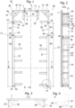
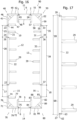
- Fig. 1 shows a first embodiment of a formwork system 10.
- the formwork system 10 for a building opening contains a first angle element 40, a second angle element 50 and at least one first profile element 11 extending between the first and the second angle element 40, 50.
- Each of the first and second angle elements 40, 50 includes a first angle element leg 41, 51 and a second angle element leg 42, 52, wherein the second angle element leg 42 of the first angle element 40 has an angle element outer surface 49, wherein the first angle element leg 51 of the second angle element 50 has an angle element outer surface 56.
- the first profile element 11 has a first profile element edge 1 and a second profile element edge 2 as well as a profile element length 5.
- the profile element length 5 extends from the first profile element edge 1 to the second profile element edge 2.
- the first profile element 11 is designed as a plate element with a rectangular surface.
- Each of the first and second angle elements 40, 50 contains a fastening element 45, 54 which is designed to fasten the first profile element 11 to the first and second angle elements 40, 50.
- the first angle element 40 has a first fastening element 44 and a second fastening element 45.
- the second fastening element 45 is designed to fasten the first profile element edge 1 of the first profile element 11 to the first angle element 40.
- the second angle element 50 has a first fastening element 54 and a second fastening element 55.
- the first fastening element 54 is designed to fasten the second profile element edge 2 of the first profile element 11 to the second angle element 50.
- the surface 6 of the profile element 11 forms a flat surface with the angle element outer surface 49 of the first angle element 50 and the angle element outer surface 56 of the second angle element 50.
- the first angle element leg 41 of the first angle element 40 contains a first fastening element 44, which is designed to receive a second profile element 12.
- the second angle element leg 52 of the second angle element 50 contains a second fastening element 55, which is designed to receive a third profile element 13.
- the second profile element 12 has a profile element length 3, see Fig. 10 .
- the third profile element 13 has a profile element length 4, see Fig. 10 .
- the first Angle element 40 thus connects the second profile element 12.
- the second profile element 12 comprises a first profile element 21 and a second profile element 22.
- the first profile element 21 is designed as a plate element with a rectangular surface.
- a third profile element 13 is also connected to the second angle element 50.
- the third profile element 13 comprises a first profile part element 31 and a second profile part element 32.
- the first profile part element 31 is designed as a plate element with a rectangular surface.
- the second profile element 12 thus comprises a first profile sub-element 21 and a second profile sub-element 22.
- the first profile sub-element 21 has a first profile sub-element edge 23 and a second profile sub-element edge 24.
- the first profile sub-element 21 has a profile sub-element length 25, wherein the profile sub-element length 25 of the first profile sub-element 21 extends from its first profile sub-element edge 23 to its second profile sub-element edge 24.
- the second profile sub-element 22 has a first profile sub-element edge 26 and a second profile sub-element edge 27.
- the second profile sub-element 22 has a profile sub-element length 28, wherein the profile sub-element length 28 of the second profile sub-element 22 extends from its first profile sub-element edge 26 to its second profile sub-element edge 27.
- the profile element length 3 results from the sum of the profile element length 25 of the first profile element 21 and the profile element length 28 of the second profile element 22.
- the third profile element 13 comprises a first profile sub-element 31 and a second profile sub-element 32.
- the first profile sub-element 31 has a first profile sub-element edge 33 and a second profile sub-element edge 34.
- the first profile sub-element 31 has a profile sub-element length 35, wherein the profile sub-element length 35 of the first profile sub-element 31 extends from its first profile sub-element edge 33 to its second profile sub-element edge 34.
- the second profile sub-element 32 has a first profile sub-element edge 36 and a second profile sub-element edge 37.
- the second profile sub-element 32 has a profile sub-element length 38, wherein the profile sub-element length 38 of the second profile sub-element 32 extends from its first profile sub-element edge 36 to its second profile sub-element edge 37.
- the profile element length 4 results from the sum of the profile element length 35 of the first profile element 31 and the profile element length 38 of the second profile element 32.
- the profile element length 5 of the first profile element 11 is adjustable.
- a first profile element 11 with any profile element length 5 can be attached to the first and second fastening elements 45, 54 of the corresponding first and second angle elements 40, 50.
- the profile element 11 can thus be used according to the desired total length L, total width B or total height H of the formwork system, see also Fig. 10 , 14 .
- the profile element length 3 of the second profile element 12 and the profile element length 4 of the third profile element 13 are also adjustable. If the second profile element 12 comprises a first profile element 21 and a second profile element 22, in particular the profile element length 25 of the first profile element 21 can be adjusted. For example, the first profile element 21 can be cut to the desired profile element length 25. According to the present exemplary embodiment, the second profile element 22 is a prefabricated component. If the third profile element 13 comprises a first profile element 31 and a second profile element 32, in particular the profile element length 35 of the first profile element 31 can be adjusted. For example, the first profile element 31 can be cut to the desired profile element length 35. According to the present exemplary embodiment, the second profile element 32 is a prefabricated component.
- the second profile part element 22 and the second profile part element 32 can be designed in the same way.
- Fig. 17 shows an embodiment of such a profile part element 22, 32.
- at least one of the first or second profile part elements 22, 32 can be designed as a frame element.
- the first angle element 40 contains at least one reinforcing element, in Fig. 1 A first reinforcing element 47 and a second reinforcing element 48 are shown as examples.
- the second angle element 50 contains at least one reinforcing element, in Fig. 1 A first reinforcing element 57 and a second reinforcing element 58 are shown as examples.
- Fig. 2 shows a section through the formwork system according to Fig. 1 along the section line BB, in which the first profile element 11 is visible in a sectional view, as well as the second angle element 50 and the third profile element 13 in a side view.
- a wall formwork 7 is shown schematically, to which the formwork system 10
- the profile element 11 is connected to the second angle element 50 via the first fastening element 54, which is Fig. 9 is shown in detail.
- the second angle element 50 according to this embodiment is connected to the wall formwork 7 by means of the first reinforcing element 57 and the second reinforcing element 58.
- the first and second reinforcing elements 57, 58 can contain openings for receiving fastening means (not shown), for example screws or nails.
- the first and second reinforcing elements 57, 58 are fastened to the wall formwork 7 by means of the fastening means or means.
- the first and second reinforcing elements 57, 58 have a triangular cross-section according to the present embodiment, which is shown in Fig. 6 shown detail for the second reinforcing element 58 is shown more clearly.
- the third profile element 13 is also visible.
- the third profile element 13 comprises the first profile part element 31 and the second profile part element 32.
- the first profile part element 31 extends from the first profile part element edge 33 to the second profile part element edge 34.
- the profile part element length 35 extends from the first profile part element edge 33 to the second profile part element edge 34, as in Fig. 1 is shown.
- the first profile part element 31 of the third profile element 13 is designed as a plate element with a rectangular surface.
- the first profile part element 31 adjoins the second angle element 50, more precisely its second angle element leg 52.
- the angle element inner surface opposite the angle element outer surface 59 is visible.
- the angle element inner surface contains an angle element recess 53.
- the second angle element leg 52 can comprise a frame element and a planking plate 9.
- This design has the advantage that the frame element can consist of a material that can ensure the load-bearing capacity of the formwork system and the planking plate 9 contains a material that can be easily removed from the concrete after the concreting work.
- the frame element can have the angle element recess 53 shown to reduce weight. According to an embodiment not shown, the frame element does not contain a recess.
- the first profile element 31 is connected to the second angle element 50 by means of the second fastening element 55.
- the first profile element 31 can be connected to the second fastening element 55 by means of screws or nails.
- the second fastening element 55 is designed as a tab which is attached to the free end of the second angle element leg 52.
- the second fastening element 55 can be arranged pivotably around the free end of the second angle element leg 52, as shown for example in detail E according to Fig. 4 for the corresponding fastening element of the second profile part element 32 or in detail D of the Fig. 8 .
- the second profile element 32 is connected to the first profile element 31 in such a way that the second profile element edge 34 of the first profile element 31 adjoins the first profile element edge 36 of the second profile element 32.
- a first fastening element 65 is attached to the first profile element edge 36 of the second profile element 32. The first fastening element 65 serves to couple the first profile element 31 to the second profile element 32.
- the second profile element 32 can be designed as a frame element.
- the profile element inner surface contains a plurality of profile element recesses 64.
- the second profile element 32 can comprise a frame element and a planking plate 9.
- This design has the advantage that the frame element can consist of a material that can ensure the load-bearing capacity of the formwork system and the planking plate 9 contains a material that can be easily removed from the concrete after the concreting work.
- the frame element can have a plurality of profile element recesses 64 to reduce weight; in the present embodiment, four profile element recesses 64 are visible as an example. According to an embodiment not shown, the frame element contains no recesses or a different number of recesses.
- the second profile part element 32 with its second profile part element edge 37 stands on a non-described base.
- the second profile element 32 contains a plurality of reinforcing elements 39, which in Fig. 1 are best visible. Of the five reinforcement elements shown as examples, Fig. 1 For simplicity, only one is provided with a reference symbol. The number of reinforcing elements 39 can differ from the number shown in individual cases. According to an embodiment not shown, the second profile part element 32 can also not contain a single reinforcing element.
- the second profile part element 22 of the second profile element 12 shown can have the same structure as the second profile part element 32 of the third profile element 13.
- Fig. 3 shows a section through the formwork system according to Fig. 1 along the section line CC, which shows the second profile element 22 of the second profile element 12 and the second profile element 32 of the third profile element 13 in section.
- a wall formwork 7 is shown, to which the formwork system 10 is connected in the installed state.
- Fig. 3 the arrangement of one reinforcing element 29 of the second profile part element 22 and one reinforcing element 39 of the second profile part element 32.
- Fig. 4 shows a detail E of the formwork system according to Fig. 1 , in which the lowermost part of the second profile element 32 of the third profile element 13 is shown.
- the detail thus shows the second profile element edge 37 as well as a part of the reinforcing element 39 closest to the second profile element edge 37.
- a second fastening element 62 is attached to the second profile element edge 37, which is arranged so as to be pivotable about the second profile element edge 37.
- Fig. 5 shows a view of the formwork system 10 according to the first embodiment in a perspective view.
- the first profile element 11, the first angle element 40 and the second profile element 12 are arranged in this view such that their outside is visible.
- the outside forms the support surface, recess surface or contact surface for a concrete masonry in which a building opening is to be made, in particular a door or a window.
- the inside of the second angle element 50 is partially visible.
- the wall formwork is omitted in this view.
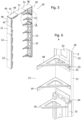
- Fig. 6 shows a detail A of the formwork system according to Fig. 5 , which shows a part of the second angle element 50.
- the third profile element 13 adjoins the angle element 50, whereby the third profile element 13 consists of the first profile element 31 and the second profile element 32.
- the first profile element 32 is completely visible, only a part of the second profile element 32 is shown.
- the first profile part element 31 also contains a reinforcing element 19.
- the reinforcing elements 19, 29, 39 according to the first embodiment contain a first reinforcing element leg, a second reinforcing element leg and a connecting strut which connects the first Reinforcing element leg with the second reinforcing element leg. At least one of the first and second reinforcing element legs can contain at least one opening for receiving a fastening means.
- the reinforcing element 19 is provided with a plurality of openings which are located on the first reinforcing element leg and on the second reinforcing element leg.
- the reinforcing element 19 is fastened with fastening means both to the wall formwork 7 and to the first profile part element 21, 31.
- the profile element 11 can also contain a reinforcing element, which is not shown in the drawing.
- Fig. 6 the inside of the second angle element 50 is shown, so this illustration shows the inside belonging to the angle element outer surface 59.
- the inside has a flat inner base surface, to which a left and a right tab are connected.
- the tab serves to stiffen the angle element outer surface, which can be designed to be thin-walled.
- a planking plate 9 is placed on the angle element outer surface, which forms the surface that comes into contact with the concrete.
- the planking plate 9 contains a surface to which no concrete adheres, so that after completion of the concrete wall, the formwork system can be easily removed from the concrete wall.
- the planking plate 9 can contain a plastic or be made of plastic.
- the planking plate 9 does not bond with the concrete and can therefore be easily removed after the concrete wall has been completed and has hardened accordingly. If the planking plate 9 is subject to wear, it can be easily replaced if necessary.
- the panel 9 may contain polyethylene or polypropylene or a similarly effective plastic.
- the angle element may contain a metal.
- the outer surface of the angle element is for direct contact with the concrete to be filled.
- the planking plate 9 can be omitted.
- angle elements and the profile elements which contain corresponding reinforcement elements.
- the angle elements, the profile elements and/or the angle elements are attached to the wall formwork using fastening means.
- the fastening means can in particular comprise screws or nails.
- the fastening elements are not shown in the drawings. Additional bracing, such as cross-beam elements, is not required.
- Fig. 7 shows a view of the formwork system according to the first embodiment in a perspective view from below.
- the first profile element 11, the first angle element 40 are arranged in this view such that their inside is at least partially visible.
- the outside of the second profile element 12 is visible, which is the support surface or contact surface for a concrete masonry in which a building opening is to be made, in particular a door or a window.
- the inside of the second angle element 50 is visible.
- the wall formwork is omitted in this view.
- Fig. 8 shows a detail D of the formwork system according to Fig. 7 , in which a part of the second profile element 32 of the profile element 13 adjoining the second profile element edge 37 is connected.
- the fastening element 66 is also visible, which is arranged on the second profile part element edge 37.
- the fastening element 66 can be pivoted in relation to the second profile part element edge 37.
- the fastening element 66 can be pivoted by an angle of up to and including 90 degrees.
- the fastening element 66 In a first pivot position, the fastening element 66 is arranged parallel to the reinforcing element 39; in a second pivot position, the fastening element 66 is arranged essentially parallel to the surface spanned by the second profile part element 32, which is not shown in the drawing.
- the fastening element 66 contains a locking element 67, for example a pin element.
- the locking element 67 is arranged in an opening of the fastening element 66.
- the locking element 67 can be removed if the fastening element 66 is to be moved from the first pivot position to the second pivot position or vice versa.
- the locking element 67 is reinserted into the opening.
- the fastening elements 44, 45, 54, 55 of the angle elements 40, 50 and of the profile part element 22 can be constructed in the same way.
- Fig. 9 shows a detail of an angle element of the formwork system according to the first embodiment.
- the first angle element 40 and the second angle element 50 have according to the Fig. 1 illustrated embodiment of the formwork system 10 has the same structure.
- the following description of an angle element is therefore equally applicable to the first and second and any further angle elements 40, 50.
- the angle element 50 contains a first angle element leg 51 and a second angle element leg 52.
- Each of the angle element legs 51, 52 has an angle element outer surface 56, 59, which is designed as a flat surface.
- the angle element outer surface can be designed to accommodate a planking plate 9, which can rest as planking on the angle element outer surface 56, 59, so that the planking plate 9 covers the angle element outer surface 56, 59 in the installed state.
- the planking plate 9 can also be omitted. According to this embodiment, the planking plate 9 forms the angle element outer surface 56, 59.
- the inner surface of the angle element opposite the corresponding outer surface of the angle element is delimited by two corner reinforcement elements, which can be provided to increase the stability of the angle element.
- At least one of the corner reinforcement elements can contain at least one opening for receiving a fastening means.
- the angle element 50 contains at least one reinforcing element, in Fig. 9 a first reinforcing element 57 and a second reinforcing element 58.
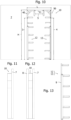
- Fig. 10 shows a view of the formwork system 10 according to the first embodiment in the installed state from the front, which is attached to a wall formwork 7.
- Fig. 10 that both the length L and the height H of the formwork system are adjustable.
- Each of the profile element lengths 3, 4, 5 can be changed by using profile elements 11, 12, 13 which are variable in their dimensions.
- Fig. 11 shows a side view of the formwork system 10 according to Fig. 10 , which is attached on one side to a wall formwork 7.
- Fig. 12 shows a side view of the formwork system 10 according to Fig. 10 , which is attached to both sides of a wall formwork 7, 8, so that the formwork system 10 extends between the wall formwork 7, 8.
- Fig. 13 shows a detail of one of the first or second profile elements 12, 13 for a formwork system 10 according to the first embodiment, to the description Fig. 1 and 2 can be referred to here.
- Each of the second partial profile elements 22, 32 can have a planking plate 9 on the outer surface, as in connection with Fig. 1 or Fig. 2 described.
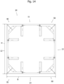
- Fig. 14 shows a view of a formwork system 20 according to a second embodiment.
- the formwork system 20 for a building opening contains a first angle element 40, a second angle element 50 and at least one first and the second angle element 2 extending first profile element 11.
- the first profile element 11 is designed as a plate element with a rectangular surface.
- the first profile element 11 has a first profile element edge and a second profile element edge as well as a profile element length.
- the profile element length extends from the first profile element edge to the second profile element edge.
- Each of the angle elements 40, 50 has a fastening element which is designed to fasten the first and second profile element edges of the first profile element 11 to the corresponding first or second angle element 40, 50.
- the profile element length 5 of the profile element 11 is adjustable. In other words, a first profile element 11 with any profile element length 5 can be fastened to the first and second fastening elements of the corresponding first and second angle elements 40, 50.
- the profile element 11 can thus be used according to the desired overall length, overall width or overall height of the formwork system.
- the formwork system 20 contains a third angle element 70 and a fourth angle element 80 as well as at least one fourth profile element 14 extending between the third angle element 70 and the fourth angle element 80.
- the formwork system 20 contains a second profile element 12, which is arranged between the first angle element 40 and the third angle element 70.
- the formwork system 20 also includes a third profile element 13, which is arranged between the second angle element 50 and the fourth angle element 80.
- Each of the angle elements 40, 50, 70, 80 can be used in connection with Fig. 1-13 described angle elements.
- Fig. 15 shows a view of a formwork system 100 according to a third embodiment.
- the formwork system 100 for a building opening contains a first angle element 103, a second angle element 153 and at least one first profile element 110 extending between the first angle element 103 and the second angle element 153.
- Each of the first and second angle elements 103, 153 contains a first angle element leg 101, 151 and a second angle element leg 102, 152.
- the first angle element leg 101 of the first angle element 103 has an angle element outer surface 106.
- the first angle element leg 151 of the second angle element 153 has an angle element outer surface 156.
- the first profile element 110 contains a first profile part element 111 and a second profile part element 121.
- the first profile part element 111 and/or the second profile part element 121 can be designed as a plate element.
- the first profile part element 111 and the second Profile part element 121 form a common corner.
- Each of the first and second profile part elements 111, 121 has a rectangular surface, wherein the first profile part element 111 has a first profile part element edge 113 and a second profile part element edge 114.
- the first profile part element 111 has a first profile part element length 115, wherein the first profile part element length 115 extends from the first profile part element edge 113 to the second profile part element edge 114 of the first profile part element 111.
- the second profile part element 121 has a second profile part element length 125, wherein the second profile part element length 125 extends from the first profile part element edge 123 to the second profile part element edge 124 of the second profile part element 121.
- Each of the first and second angle elements 103, 153 has a fastening element 104, 154 which is designed to fasten the first profile element 110 to the first and second angle elements 103, 153 in such a way that the surface 116 of the first profile element 111 forms a flat surface with the angle element outer surface 106 of the first angle element 103, and the surface 126 of the second profile element 121 forms a flat surface with the angle element outer surface 156 of the second angle element.
- At least one of the profile element lengths 115, 125 is adjustable. In other words, a first profile element 111 with any profile element length 115 can be combined with a second profile element 121 with any profile element length 125.
- the first profile element 110 can be used according to the desired total length or total width of the formwork system 100.
- the first profile element 111 is arranged in particular at an angle of 90 degrees to the second profile element 121.
- the second profile element edge 114 of the first profile element 111 rests on the inner surface of the second profile element 121.
- the inner surface is arranged opposite the surface 126.
- the second angle element legs 102, 152 of the first angle element 103 and the second angle element 153 can be connected to a second profile element 130 in such a way that a common closed outer surface is formed by the first and second angle elements 103, 153 and the first and second profile elements 110, 130.
- the outer surface of the formwork system can be square.
- At least one of the angle element outer surfaces contains a planking plate 119.
- each of the first and second angle elements 103, 153 may include a first and a second reinforcing element 107, 108, 157, 158.
- a second profile element 120 is provided, which is fastened to the second angle element leg 102 of the first angle element 102 and to the second angle element leg 152 of the second angle element 153, so that a building opening that is closed on all sides is formed, for example for a window.
- the second profile element 120 contains a third profile part element 131 and a fourth profile part element 141.
- the third profile part element 131 and/or the fourth profile part element 141 can be designed as a plate element.
- the third profile part element 131 and the fourth profile part element 141 form a common corner.
- Each of the third and fourth profile part elements 131, 141 has a rectangular surface, wherein the third profile part element 131 has a first profile element edge 133 and a second profile element edge 134.
- the third profile part element 131 has a third profile part element length 135, wherein the third profile part element length 135 extends from the first profile part element edge 133 to the second profile part element edge 134 of the third profile part element 131.
- the fourth profile part element 141 has a first profile element edge 143 and a second profile element edge 144.
- the fourth profile part element 141 has a fourth profile part element length 145, wherein the fourth profile part element length 145 extends from the first profile part element edge 143 to the second profile part element edge 144 of the fourth profile part element 141.
- Each of the first and second angle elements 103, 153 has a fastening element 105, 155 which is designed to fasten the second profile element 120 to the first and second angle elements 103, 153 in such a way that the surface 136 of the third profile element 131 forms a flat surface with the angle element outer surface 109 of the first angle element 103, and the surface 146 of the fourth profile element 141 forms a flat surface with the angle element outer surface 159 of the second angle element 153.
- At least one of the third and fourth profile element lengths 135, 145 is adjustable. In other words, a third profile element 131 with any profile element length 135 can be combined with a fourth profile element 141 with any profile element length 145.
- Each of the first, second, third and fourth profile part elements 111, 121, 131, 141 can contain a reinforcing element.
- the first profile part element 111 contains a reinforcing element 112 and the fourth profile part element contains a reinforcing element 142.
- Fig. 16 shows a view of a formwork system 90 according to a fourth embodiment, which differs from the formwork system 10 of the first embodiment in that a fifth profile element 15 and a sixth profile element 16 are connected to the free ends of the profile elements 12, 13.
- a third angle element 70 and a fourth angle element 80 are connected to the fifth profile element 15 and the sixth profile element 16.
- a fourth profile element 14 extends between the third angle element 70 and the fourth angle element 80.
- the formwork system 90 for a building opening contains a first angle element 40, a second angle element 50 and at least one first profile element 11 extending between the first and second angle elements 40, 50.
- the formwork system 90 for a building opening further contains a third angle element 70, a fourth angle element 80 and at least one fourth profile element 14 extending between the third and fourth angle elements 70, 80.
- Each of the first and second angle elements 40, 50 includes a first angle element leg 41, 51 and a second angle element leg 42, 52, wherein the second angle element leg 42 of the first angle element 40 has an angle element outer surface 49, wherein the first angle element leg 51 of the second angle element 50 has an angle element outer surface 56.
- the first profile element 11 has a first profile element edge 1 and a second profile element edge 2 as well as a profile element length 5.
- the profile element length 5 extends from the first profile element edge 1 to the second profile element edge 2.
- the first profile element 11 is designed as a plate element with a rectangular surface.
- Each of the first and second angle elements 40, 50 contains a fastening element 45, 54 which is designed to fasten the first profile element 11 to the first and second angle elements 40, 50.
- the first angle element 40 has a first fastening element 44 and a second fastening element 45.
- the second fastening element 45 is designed to fasten the first profile element edge 1 of the first profile element 11 to the first angle element 40.
- the second angle element 50 has a first fastening element 54 and a second fastening element 55.
- the first fastening element 54 is designed to fasten the second profile element edge 2 of the first profile element 11 to the second angle element 50.
- the surface 6 of the Profile element 11 forms a flat surface with the angle element outer surface 49 of the first angle element 50 and the angle element outer surface 56 of the second angle element 50.
- the first angle element leg 41 of the first angle element 40 contains a first fastening element 44, which is designed to receive a second profile element 12.
- the second angle element leg 52 of the second angle element 50 contains a second fastening element 55, which is designed to receive a third profile element 13.
- the second profile element 12 has a profile element length 3, see Fig. 10 .
- the third profile element 13 has a profile element length 4, see Fig. 10 .
- the second profile element 12 is thus connected to the first angle element 40.
- the second profile element 12 comprises a first profile element 21 and a second profile element 22.
- the first profile element 21 is designed as a plate element with a rectangular surface.
- a third profile element 13 is also connected to the second angle element 50.
- the third profile element 13 comprises a first profile part element 31 and a second profile part element 32.
- the first profile part element 31 is designed as a plate element with a rectangular surface.
- the second profile element 12 thus comprises a first profile sub-element 21 and a second profile sub-element 22.
- the first profile sub-element 21 has a first profile sub-element edge 23 and a second profile sub-element edge 24.
- the first profile sub-element 21 has a profile sub-element length 25, wherein the profile sub-element length 25 of the first profile sub-element 21 extends from its first profile sub-element edge 23 to its second profile sub-element edge 24.
- the second profile sub-element 22 has a first profile sub-element edge 26 and a second profile sub-element edge 27.
- the second profile sub-element 22 has a profile sub-element length 28, wherein the profile sub-element length 28 of the second profile sub-element 22 extends from its first profile sub-element edge 26 to its second profile sub-element edge 27.
- the profile element length 3 results from the sum of the profile element length 25 of the first profile element 21 and the profile element length 28 of the second profile element 22.
- the third profile element 13 comprises a first profile element 31 and a second profile element 32.
- the first profile element 31 has a first profile element edge 33 and a second profile element edge 34.
- the first profile element 31 has a profile element length 35, wherein the Profile part element length 35 of the first profile part element 31 extends from its first profile part element edge 33 to its second profile part element edge 34.
- the second profile part element 32 has a first profile part element edge 36 and a second profile part element edge 37.
- the second profile part element 32 has a profile part element length 38, wherein the profile part element length 38 of the second profile part element 32 extends from its first profile part element edge 36 to its second profile part element edge 37.
- the profile element length 4 results from the sum of the profile element length 35 of the first profile element 31 and the profile element length 38 of the second profile element 32.
- Each of the third and fourth angle elements 70, 80 includes a first angle element leg 71, 81 and a second angle element leg 72, 82, wherein the second angle element leg 72 of the third angle element 70 has an angle element outer surface 79, wherein the first angle element leg 81 of the second angle element 80 has an angle element outer surface 86.
- the fourth profile element 14 has a first profile element edge 1 and a second profile element edge 2 as well as a profile element length 5, which correspond to the first profile element 11 and therefore the same reference numerals have been used.
- the profile element length 5 extends from the first profile element edge 1 to the second profile element edge 2.
- the fourth profile element 14 is designed according to this embodiment as a plate element with a rectangular surface.
- Each of the third and fourth angle elements 70, 80 contains a fastening element 75, 84 which is designed to fasten the fourth profile element 14 to the third and fourth angle elements 70, 80.
- the third angle element 70 has a first fastening element 74 and a second fastening element 75.
- the second fastening element 75 is designed to fasten the first profile element edge 1 of the fourth profile element 14 to the third angle element 70.
- the fourth angle element 80 has a first fastening element 84 and a second fastening element 85.
- the first fastening element 84 is designed to fasten the second profile element edge 2 of the fourth profile element 14 to the fourth angle element 80.
- the surface 6 of the fourth profile element 14 forms a flat surface with the angle element outer surface 79 of the first angle element 70 and the angle element outer surface 86 of the second angle element 80.
- the first angle element leg 71 of the first angle element 70 contains a first fastening element 74, which is designed to receive a fifth profile element 15.
- the second angle element leg 82 of the second angle element 80 contains a second fastening element 85, which is designed to receive a sixth profile element 16.
- the fifth profile element 15 has a profile element length 17.
- the sixth profile element 16 has a profile element length 18.
- the fifth profile element 15 thus adjoins the third angle element 70.
- the sixth profile element 16 thus adjoins the fourth angle element 80.
- the second profile element 12 comprises a first profile element 21 and a second profile element 22.
- the first profile element 21 is designed as a plate element with a rectangular surface.
- a third profile element 13 is also connected to the second angle element 50. According to Fig. 16 the third profile element 13 comprises a first profile part element 31 and a second profile part element 32.
- the first profile part element 31 is designed as a plate element with a rectangular surface.
- the profile element length 5 of the first profile element 14 is adjustable.
- a fourth profile element 14 with any profile element length 5 can be attached to the third and fourth fastening elements 75, 84 of the corresponding third and fourth angle elements 70, 80.
- the profile element 14 can thus be used according to the desired total length L, total width B or total height H of the formwork system.
- the profile element length 3 of the second profile element 12 and the profile element length 4 of the third profile element 13 are also adjustable. If the second profile element 12 comprises a first profile element 21 and a second profile element 22, in particular the profile element length 25 of the first profile element 21 can be adjusted. For example, the first profile element 21 can be cut to the desired profile element length 25. According to the present exemplary embodiment, the second profile element 22 is a prefabricated component. If the third profile element 13 comprises a first profile element 31 and a second profile element 32, in particular the profile element length 35 of the first profile element 31 can be adjusted. For example, the first profile element 31 can be cut to the desired profile element length 35. According to the present exemplary embodiment, the second profile element 32 is a prefabricated component.
- the second profile part element 22 and the second profile part element 32 can be designed in the same way.
- Fig. 17 shows an embodiment of such a profile part element 22, 32.
- at least one of the second profile part elements 22, 32 can be designed as a frame element.
- the first angle element 40 contains at least one reinforcing element, in Fig. 16 A first reinforcing element 47 and a second reinforcing element 48 are shown as examples.
- the second angle element 50 contains at least one reinforcing element, in Fig. 16 A first reinforcing element 57 and a second reinforcing element 58 are shown as examples.
- the third angle element 70 contains at least one reinforcing element, in Fig. 16 A first reinforcing element 77 and a second reinforcing element 78 are shown as examples.
- the second angle element 80 contains at least one reinforcing element, in Fig. 16 A first reinforcing element 87 and a second reinforcing element 88 are shown as examples.
- the fifth profile element 15 and the sixth profile element 16 can be omitted.
- the third angle element 70 is arranged adjacent to the second profile part element 22 of the second profile element 12.
- the fourth angle element 80 is arranged adjacent to the second profile part element 32 of the third profile element 13 according to this embodiment.
- Fig. 17 shows a detail of a profile part element 22 for a formwork system 90 according to a fourth embodiment.
- This profile part element corresponds to the profile part element of the first embodiment, therefore the same reference numerals are used for it.
- the profile part element 22 has a profile part element length 28 which extends from the first profile part element edge 26 to the second profile part element edge 27.
- a first fastening element 61 is attached to the first profile element edge 26 of the second profile element 22.
- the first fastening element 61 serves to couple the first profile element 21 to the second profile element 22.
- the fastening element 62 is also visible, which is arranged on the second profile part element edge 27.
- the fastening element 62 is pivotable with respect to the second profile part element edge 27.
- the fastening element 62 is pivotable by an angle of up to and including 90 degrees.
- the fastening element 62 In a first In a first pivot position, the fastening element 62 is arranged parallel to the reinforcing element 29, which is not shown in the drawing; in a second pivot position, the fastening element 62 is arranged essentially parallel to the surface spanned by the second profile part element 32.
- the fastening element 62 contains a locking element 63, for example a pin element.
- the locking element 63 is arranged in an opening in the fastening element 62.
- the locking element 63 can be removed if the fastening element 62 is to be moved from the first pivot position to the second pivot position or vice versa. When the desired pivot position is reached, the locking element 63 is inserted back into the opening.
- the fastening element 62 can comprise one hinge half each, with one hinge half being arranged on the fifth profile element 15 and the second hinge half on the profile part element 22.
- the first hinge half can be pivoted away if no profile element 15 is attached to it.
- a hinge is formed from the two hinge halves in interaction with the locking element 63.
- Such hinges can be provided for attaching each of the first to sixth profile elements 11, 12, 13, 14, 15, 16.
- the distance of the fastening element 62 from the outer surface 68 corresponds in the Fig. 17 shown pivot position of the thickness of the fifth profile element 15. This ensures that the outer surface 68 is flush with the outer surface of the fifth profile element 15.
- the fastening element 62 can be attached in such a way that differences in thickness between a planking plate and the fifth profile element 15 can be compensated.
- the planking plate can have a thickness of 15 mm and the fifth profile element 15 a thickness of 27 mm.
- the fastening element can be inserted into the Fig. 17 not shown swivel position, which is also possible in Fig. 8 for the fastening element 66 of the profile part element 32.
- the formwork system 10, 20, 90, 100 for a building opening thus contains at least one angle element 40, 50, 70, 80, 103, 153 and at least one profile element 11, 12, 13, 14, 15, 16, 110, 120. At least some of the profile elements 11, 12, 13, 14, 15, 16, 110, 120 have a profile element length 3, 4, 5, 115, 125, 135, 145, which is adjustable.
- the formwork system for concrete walls and ceilings therefore comprises at least one angle element or at least one profile element that contains a planking panel.
- the angle element or the profile element containing the planking panel is supplemented with at least one patch piece so that a flush formwork is available.
- the patch piece or patch pieces are designed as profile elements, for example formwork panels can be used.
- Each of the profile elements and each of the paneling panels according to each of the embodiments can be designed as a plastic profile.
- the profile element can be manufactured continuously using an extrusion process and subsequently cut to the desired length.
Landscapes
- Engineering & Computer Science (AREA)
- Architecture (AREA)
- Mechanical Engineering (AREA)
- Civil Engineering (AREA)
- Structural Engineering (AREA)
- Forms Removed On Construction Sites Or Auxiliary Members Thereof (AREA)
Abstract
Ein Schalungssystem (10) für eine Gebäudeöffnung enthält mindestens ein Winkelelement (40, 50) und mindestens ein Profilelement (11, 12, 13) Zumindest ein Teil der Profilelemente (11, 12, 13) weist eine Profilelementlänge (3, 4, 5) auf, die einstellbar ist.
Description
- Die vorliegende Erfindung betrifft ein Schalungssystem für eine Gebäudeöffnung, beispielsweise eine Tür oder ein Fenster.
- In dem Dokument
DE 20 2017 103 751 U wird eine gattungsgemässe Laibungsschalung zum Schalen einer Öffnung in einem Betonteil gezeigt. Diese Laibungsschalung weist zwei Schaltafeln auf, die mit ihren Schalflächen in einem Winkel zueinander angeordnet sind. Die Schalflächen grenzen an einer gemeinsamen Kante aneinander, um eine Ecke auszubilden. Die Schaltafeln sind mit einem Winkelverbinder verbunden, sodass die Schaltafeln eine im Wesentlichen quadratische Öffnung ausbilden. Zur Versteifung der Laibungsschalung sind zusätzlich horizontale und vertikale Spindelstützen erforderlich. Für diese vorbekannte Lösung werden Schaltafeln benötigt, welche die Abmessungen der Öffnung aufweisen, sie sind also nur für Öffnungen mit einer genau bestimmten Länge und Breite verwendbar. Aus dem DokumentCN210177944U ist ein Schalungssystem für eine Gebäudeöffnung bekannt, welches teleskopische Balkenelemente zwischen Winkelverbindern zeigt. Dieses Schalungssystem kann für Gebäudeöffnungen unterschiedlicher Grösse verwendet werden, weil die teleskopischen Balkenelemente auf die gewünschte Breite oder Höhe angepasst werden können. Die Winkelelemente werden diagonal mit Spannelementen verspannt. Zudem sind vertikale und horizontale Stützelemente erforderlich, deren Höhe bzw. Breite an die entsprechende Breite oder Höhe der Gebäudeöffnung angepasst werden kann. Diese Lösung ist zwar universell einsetzbar, aber aufwändig zu installieren. Die Winkelelemente müssen zudem vorgespannt werden, sodass die teleskopischen Balkenelemente an ihrer Position verbleiben, wodurch der Innenraum nach Montage des Schalungssystems nicht mehr zugänglich ist. Alternativ ist es auch möglich, dass die Winkelverbinder selbst teleskopische Arme aufweisen, siehe DokumentGB 2 162 230 A - Es ist Aufgabe der Erfindung, ein Schalungssystem für eine Gebäudeöffnung bereitzustellen, die für Gebäudeöffnungen mit unterschiedlichen Abmessungen verwendet werden kann. Das erfindungsgemässe Schalungssystem ist für verschiedene Gebäudeöffnungen verwendbar. Das Schalungssystem kann leicht, sogar manuell, von einer Person hergestellt und auch wieder entfernt werden. Zudem ist es Aufgabe der Erfindung ein Schalungssystem bereitzustellen, welches nicht zu Verschmutzungen neigt bzw. nach Verschmutzung einfach und schnell gereinigt werden kann.
- Die Lösung der Aufgabe der Erfindung erfolgt durch einen Schalungssystem gemäss Anspruch 1 oder Anspruch 7. Vorteilhafte Ausführungsbeispiele des Schalungssystems gemäss Anspruch 1 sind Gegenstand der Ansprüche 2 bis 6. Vorteilhafte Ausführungsbeispiele des Schalungssystems gemäss Anspruch 7 sind Gegenstand der Ansprüche 8 bis 10.
- Wenn der Begriff "beispielsweise" in der nachfolgenden Beschreibung verwendet wird, bezieht sich dieser Begriff auf Ausführungsbeispiele und/oder Ausführungsformen, was nicht notwendigerweise als eine bevorzugtere Anwendung der Lehre der Erfindung zu verstehen ist. In ähnlicher Weise sind die Begriffe "vorzugsweise", "bevorzugt" zu verstehen, indem sie sich auf ein Beispiel aus einer Menge von Ausführungsbeispielen und/oder Ausführungsformen beziehen, was nicht notwendigerweise als eine bevorzugte Anwendung der Lehre der Erfindung zu verstehen ist. Dementsprechend können sich die Begriffe "beispielsweise", "vorzugsweise" oder "bevorzugt" auf eine Mehrzahl von Ausführungsbeispielen und/oder Ausführungsformen beziehen.
- Die nachfolgende detaillierte Beschreibung enthält verschiedene Ausführungsbeispiele für das erfindungsgemässe Schalungssystem. Die Beschreibung eines bestimmten Schalungssystems ist nur als beispielhaft anzusehen. In der Beschreibung und den Ansprüchen werden die Begriffe "enthalten", "umfassen", "aufweisen" als "enthalten, aber nicht beschränkt auf" interpretiert.
- Ein Schalungssystem für eine Gebäudeöffnung umfasst ein erstes Winkelelement, ein zweites Winkelelement sowie zumindest ein sich zwischen dem ersten Winkelelement und dem zweiten Winkelelement erstreckendes erstes Profilelement, wobei jedes der ersten und zweiten Winkelelemente einen ersten Winkelelementschenkel und einen zweiten Winkelelementschenkel enthalten. Der zweite Winkelelementschenkel des ersten Winkelelements weist eine Winkelelementaussenfläche auf. Der erste Winkelelementschenkel des zweiten Winkelelements weist eine Winkelelementaussenfläche auf. Das erste Profilelement weist eine erste Profilelementkante und eine zweite Profilelementkante auf, wobei das erste Profilelement eine Profilelementlänge aufweist, wobei sich die Profilelementlänge von der ersten Profilelementkante zur zweiten Profilelementkante erstreckt. Jedes der ersten und zweiten Winkelelemente enthält je ein Befestigungselement, welches zur Befestigung des ersten Profilelements an dem ersten und zweiten Winkelelement derart ausgebildet ist, sodass die Oberfläche des ersten Profilelements mit der Winkelelementaussenfläche des ersten Winkelelements und der Winkelelementaussenfläche des zweiten Winkelelements eine ebene Fläche ausbildet. Der erste Winkelelementschenkel des ersten Winkelelements enthält ein erstes Befestigungselement, welches zur Aufnahme eines zweiten Profilelements ausgebildet ist. Der zweite Winkelelementschenkel des zweiten Winkelelements enthält ein zweites Befestigungselement, welches zur Aufnahme eines dritten Profilelements ausgebildet ist. Das zweite Profilelement weist eine Profilelementlänge auf und das dritte Profilelement weist eine Profilelementlänge auf. Die Profilelementlänge des ersten Profilelements, sowie zumindest eine der Profilelementlängen zumindest eines des zweiten Profilelements und des dritten Profilelements sind einstellbar. Zumindest eines der ersten, zweiten und dritten Profilelemente ist als ein formstabiles Bauelement ausgebildet. Mit einem formstabilen Bauelement ist insbesondere ein Blattelement oder ein Tafelelement gemeint, welches beispielsweise einen Holzwerkstoff oder einen Kunststoff enthält.
- Insbesondere kann das Schalungssystem erste und zweite Winkelelemente aufweisen. Zwischen den ersten und zweiten Winkelelementen kann flächenbündig ein erstes Profilelement montiert werden, welches in der Länge einstellbar ist. An die noch freien Enden der ersten und zweiten Winkelelemente kann je ein zweites und drittes Profilelement montiert werden, wobei auch die Länge der zweiten und dritten Profilelemente einstellbar ist. Mit dem Begriff «einstellbar» ist gemeint, dass die Länge jedes der ersten, zweiten oder dritten Profilelemente anpassbar ist. Mit anderen Worten können Profilelemente unterschiedlicher Länge verwendet werden. Die Länge der Profilelemente kann beispielsweise durch Zuschneiden verkürzt werden. Insbesondere kann das formstabile Bauelement einfach auf die gewünschte Länge zugeschnitten werden.
- Die Profilelemente können auf einer Baustelle einfach so zugeschnitten werden, dass ein Schalungssystem mit der korrekten Länge und der korrekten Höhe erhältlich ist.
- Gemäss eines Ausführungsbeispiels ist das erste Profilelement als ein Plattenelement mit rechteckiger Oberfläche ausgebildet. Ein derartiges Profilelement kann vielseitig eingesetzt werden. Daher ist ein derartiges Profilelement üblicherweise ohnehin auf einer Baustelle verfügbar und muss nicht separat bestellt werden. Wenn vorhanden, kann als Profilelement eine Schaltafel verwendet werden. Gemäss eines Ausführungsbeispiels enthält das Profilelement einen Kunststoff, insbesondere kann das Profilelement als ein Kunststoffprofil ausgebildet sein.
- Gemäss eines Ausführungsbeispiels enthalten das zweite Profilelement und das dritte Profilelement je ein erstes Profilteilelement und ein zweites Profilteilelement. Insbesondere kann zumindest eines der ersten oder zweiten Profilteilelemente eine vorgegebene Profilteilelementlänge aufweisen. Das Profilteilelement mit der vorgegebenen Profilteilelementlänge kann mit einem Profilteilelement gekoppelt werden, dessen Profilteilelement einfach vor Ort verändert werden kann, insbesondere auf die benötigte Profilteilelementlänge zugeschnitten werden kann.
- Gemäss eines Ausführungsbeispiels ist zumindest eines der ersten Profilteilelemente als in Plattenelement mit rechteckiger Oberfläche ausgebildet. Ein derartiges Plattenelement mit rechteckiger Oberfläche benötigt wenig Platz und kann daher auf einer Baustelle vorrätig gehalten werden.
- Gemäss eines Ausführungsbeispiels umfasst zumindest eines der zweiten Profilteilelemente ein Rahmenelement. Ein derartiges Rahmenelement kann insbesondere ein Skelettelement aus einem Werkstoff hoher Festigkeit, beispielsweise aus einem Metall umfassen. Das Skelettelement kann mit mindestens einer Beplankungsplatte verbunden sein. Die Beplankungsplatte ist insbesondere derart ausgebildet, dass Beton auf deren Oberfläche nicht haftet, sodass das Profilteilelement nach Fertigstellung der Betonwand einfach entfernt werden kann, weil kein Beton auf der Oberfläche der Beplankungsplatte haften kann. Gemäss eines Ausführungsbeispiels enthält die Beplankungsplatte einen Kunststoff, insbesondere kann das Profilelement als ein Kunststoffprofil ausgebildet sein. Beispielsweise kann die Beplankungsplatte Polypropylen oder Polyethylen enthalten.
- Gemäss eines Ausführungsbeispiels schliessen an das zweite Profilelement ein drittes Winkelelement und an das dritte Profilelement ein viertes Winkelelement an, wobei zwischen dem dritten und dem vierten Winkelelement ein viertes Profilelement angeordnet ist. Gemäss dieses Ausführungsbeispiels ist ein Schalungssystem für eine viereckige Öffnung erhältlich, beispielsweise für ein Fenster.
- Ein Schalungssystem für eine Gebäudeöffnung gemäss eines Ausführungsbeispiels enthält ein erstes Winkelelement, ein zweites Winkelelement sowie zumindest ein sich zwischen dem ersten Winkelelement und dem zweiten Winkelelement erstreckendes erstes Profilelement. Jedes der ersten und zweiten Winkelelemente enthalten einen ersten Winkelelementschenkel und einen zweiten Winkelelementschenkel. Der erste Winkelelementschenkel des ersten Winkelelements weist eine Winkelelementaussenfläche auf. Der erste Winkelelementschenkel des zweiten Winkelelements weist eine Winkelelementaussenfläche auf. Das erste Profilelement enthält ein erstes Profilteilelement und ein zweites Profilteilelement, wobei das erste Profilteilelement und das zweite Profilteilelement eine gemeinsame Ecke ausbilden. Jedes der ersten und zweiten Profilteilelemente weist eine rechteckige Oberfläche auf, wobei das erste Profilteilelement eine erste Profilelementkante und eine zweite Profilelementkante aufweist. Das erste Profilteilelement weist eine erste Profilteilelementlänge auf, wobei sich die erste Profilteilelementlänge von der ersten Profilteilelementkante zur zweiten Profilteilelementkante des ersten Profilteilelements erstreckt. Das zweite Profilteilelement weist eine erste Profilelementkante und eine zweite Profilelementkante auf. Das zweite Profilteilelement weist eine zweite Profilteilelementlänge auf, wobei sich die erste Profilteilelementlänge von der ersten Profilteilelementkante zur zweiten Profilteilelementkante des zweiten Profilteilelements erstreckt. Jedes der ersten und zweiten Winkelelemente weist je ein Befestigungselement auf, welches zur Befestigung des ersten Profilelements an dem ersten und zweiten Winkelelement derart ausgebildet ist, dass die Oberfläche des ersten Profilteilelements mit der Winkelelementaussenfläche des ersten Winkelelements eine ebene Fläche ausbildet, und die Oberfläche des zweiten Profilteilelements mit der Winkelelementaussenfläche des zweiten Winkelelements eine ebene Fläche ausbildet. Zumindest eine der Profilteilelementlängen ist einstellbar. Gemäss dieses Ausführungsbeispiels ist ein Schalungssystem für eine viereckige Öffnung erhältlich, beispielsweise für ein Fenster.
- Gemäss eines Ausführungsbeispiels sind die zweiten Winkelelementschenkel des ersten Winkelelements und des zweiten Winkelelements mit einem zweiten Profilelement derart verbunden, dass von den ersten und zweiten Winkelelementen und den ersten und zweiten Profilelementen eine gemeinsame geschlossene Aussenfläche ausgebildet ist. Gemäss eines Ausführungsbeispiels ist die Aussenfläche viereckig ausgebildet. Gemäss eines Ausführungsbeispiels enthält zumindest eine der Winkelelementaussenflächen eine Beplankungsplatte.
- Ein Profilelement oder Profilteilelement oder Winkelelement, welches eine Beplankungsplatte enthält, kann eine Komponente enthalten, welche die Festigkeit und Formstabilität des Schalungssystems gewährleistet und eine weitere Komponente, die sich nach Abschluss der Betonierungsarbeiten besonders einfach vom Beton abtrennen lässt.
- Der Einsatz von teleskopischen, mit anderen Worten verstellbaren, Balkenelementen, wie in
CN210177944U beschrieben, bedingt dass jedes verstellbare Balkenelement, welches meistens aus Stahl besteht, entweder für die Montage/Demontage des Schalungssystems und/oder für andere gewünschte Abmessungen betätigt werden muss. Der Einsatz von derartigen verstellbaren Balkenelementen kann aber neben des erhöhten Montageaufwands folgende Nachteile haben:
Alle beweglichen Komponenten (sei es Spannschlösser, Gewindestangen, oder Teleskopführungen) haben Führungs- und Gleitebenen. Diese Führungs- und Gleitebenen werden im rauen Baustelleneinsatz mit Beton, Betonwasser, oder Staub verschmutzt. Verschmutzung kann nicht nur die Gleiteigenschaften entlang der Gleitebenen beeinträchtigen, sondern auch die Gleitflächen derart beschädigen, dass sie nicht mehr brauchbar und somit nicht mehr funktionsfähig sind. - Die vorbekannten teleskopischen Balkenelemente sind massiv gebaut und bestehen aus Metall, üblicherweise aus Stahl. Infolge ihres Eigengewichts sind sie insbesondere für eine Person allein nicht montierbar oder demontierbar. Ferner ist bekannt, dass Schalungssysteme mit verstellbaren Komponenten den Betondruck auf das gegenüberliegende Element des Schalungssystems weiterleiten.
- Mittels des erfindungsgemässen Schalungssystems werden durch den Betondruck verursachten Kräfte des Betondrucks an die stabile Wandschalung weitergeleitet. Damit kann das erfindungsgemässe Schalungssystem deutlich schlanker und leichter gebaut werden.
- Zudem hat sich als nachteilig erwiesen, dass Schalungssysteme, die verstellbare Balkenelemente enthalten, eine Vielzahl von Komponenten aufweisen, wobei die Anzahl der zusätzlichen Komponenten mindestens um die Anzahl der verstellbaren Komponenten zu erhöhen ist. Mehr Komponenten bedeutet höhere Beschaffungskosten und mehr Aufwand in der Handhabung des Schalungssystems auf der Baustelle. Beispielsweise werden im Dokument
CN210177944U je ein diagonal angeordnetes Schraubspannelement (10) und zwei Einstellstangen (11) benötigt, um den Rahmen zusammenzuhalten. Zudem wird eine teleskopisches Balkenelement (3) für die Beplankung verwendet. - Erfindungsgemäss sind keinerlei längenverstellbare Komponenten zum Spannen, Sperren oder Abstützen erforderlich. Auf eine Abstützung der ersten zweiten, dritten Profilelemente kann erfindungsgemäss verzichtet werden, was die Montage, Demontage und Anpassung der Abmessungen deutlich vereinfacht. Jedes der ersten zweiten, dritten Profilelemente besteht somit nur aus einer einzigen Komponente. Mit anderen Worten ist zumindest eines der ersten zweiten oder dritten Profilelemente als ein einziges formstabiles Bauelement ausgebildet. Jedes der ersten, zweiten oder dritten Profilelemente kann individuell durch entsprechenden Zuschnitt angepasst werden.
- Zudem weisen die erfindungsgemässen Profilelemente ein geringes Eigengewicht auf, um eine Schalungsöffnung effizient zu versetzen, zu montieren oder zu demontieren. Eine einzelne Person kann die Montage oder Demontage oder Versetzung ohne Kran schnell und kostengünstig ausführen.
- Nachfolgend wird das erfindungsgemässe Schalungssystem anhand einiger Ausführungsbeispiele dargestellt. Es zeigen
-
Fig. 1 eine Ansicht eines Schalungssystems gemäss eines ersten Ausführungsbeispiels, -
Fig. 2 einen Schnitt durch das Schalungssystem gemässFig. 1 entlang der Schnittlinie B-B, -
Fig. 3 einen Schnitt durch das Schalungssystem gemässFig. 1 entlang der Schnittlinie C-C, -
Fig. 4 ein Detail E des Schalungssystems gemässFig. 1 , -
Fig. 5 eine Ansicht des Schalungssystems gemäss des ersten Ausführungsbeispiels, -
Fig. 6 ein Detail A des Schalungssystems gemässFig. 5 , -
Fig. 7 eine Ansicht des Schalungssystems gemäss des ersten Ausführungsbeispiels, -
Fig. 8 ein Detail D des Schalungssystems gemässFig. 7 , -
Fig. 9 ein Detail eines Winkelelements des Schalungssystems gemäss des ersten Ausführungsbeispiels, -
Fig. 10 eine Ansicht eines Schalungssystems gemäss eines ersten Ausführungsbeispiels im Einbauzustand von vorne, -
Fig. 11 eine Seitenansicht des Schalungssystems gemässFig. 10 , -
Fig. 12 eine Seitenansicht des Schalungssystems gemässFig. 10 , -
Fig. 13 ein Detail eines Profilelements für ein Schalungselement, -
Fig. 14 eine Ansicht eines Schalungssystems gemäss eines zweiten Ausführungsbeispiels, -
Fig. 15 eine Ansicht eines Schalungssystems gemäss eines dritten Ausführungsbeispiels, -
Fig. 16 eine Ansicht eines Schalungssystems gemäss eines vierten Ausführungsbeispiels, -
Fig. 17 ein Detail eines Schalungselements für ein Schalungssystem gemäss eines vierten Ausführungsbeispiels. -
Fig. 1 zeigt ein erstes Ausführungsbeispiel eines Schalungssystems 10. Das Schalungssystem 10 für eine Gebäudeöffnung enthält ein erstes Winkelelement 40, ein zweites Winkelelement 50 sowie zumindest ein sich zwischen dem ersten und dem zweiten Winkelelement 40, 50 erstreckendes erstes Profilelement 11. - Jedes der ersten und zweiten Winkelelemente 40, 50 enthält einen ersten Winkelelementschenkel 41, 51 und einen zweiten Winkelelementschenkel 42, 52, wobei der zweite Winkelelementschenkel 42 des ersten Winkelelements 40 eine Winkelelementaussenfläche 49 aufweist, wobei der erste Winkelelementschenkel 51 des zweiten Winkelelements 50 eine Winkelelementaussenfläche 56 aufweist.
- Das erste Profilelement 11 weist eine erste Profilelementkante 1 und eine zweite Profilelementkante 2 sowie eine Profilelementlänge 5 auf. Die Profilelementlänge 5 erstreckt sich von der ersten Profilelementkante 1 zur zweiten Profilelementkante 2. Das erste Profilelement 11 ist gemäss dieses Ausführungsbeispiels als ein Plattenelement mit rechteckiger Oberfläche ausgebildet.
- Jedes der ersten und zweiten Winkelelemente 40, 50 enthält je ein Befestigungselement 45, 54, welches zur Befestigung des ersten Profilelements 11 an dem ersten und zweiten Winkelelement 40, 50 ausgebildet ist. Gemäss des vorliegenden Ausführungsbeispiels weist das erste Winkelelement 40 ein erstes Befestigungselement 44 und ein zweites Befestigungselement 45 auf. Das zweite Befestigungselement 45 ist zur Befestigung der ersten Profilelementkante 1 des ersten Profilelements 11 an dem ersten Winkelelement 40 ausgebildet. Gemäss des vorliegenden Ausführungsbeispiels weist das zweite Winkelelement 50 ein erstes Befestigungselement 54 und ein zweites Befestigungselement 55 auf. Das erste Befestigungselement 54 ist Befestigung der zweiten Profilelementkante 2 des ersten Profilelements 11 an dem zweiten Winkelelement 50 ausgebildet. Die Oberfläche 6 des Profilelements 11 bildet mit der Winkelelementaussenfläche 49 des ersten Winkelelements 50 und der Winkelelementaussenfläche 56 des zweiten Winkelelements 50 eine ebene Fläche aus.
- Der erste Winkelelementschenkel 41 des ersten Winkelelements 40 enthält ein erstes Befestigungselement 44, welches zur Aufnahme eines zweiten Profilelements 12 ausgebildet ist. Der zweite Winkelelementschenkel 52 des zweiten Winkelelements 50 enthält ein zweites Befestigungselement 55, welches zur Aufnahme eines dritten Profilelements 13 ausgebildet ist. Das zweite Profilelement 12 weist eine Profilelementlänge 3 auf, siehe
Fig. 10 . Das dritte Profilelement 13 weist eine Profilelementlänge 4 auf, sieheFig. 10 . An das erste Winkelelement 40 schliesst somit das zweite Profilelement 12 an. GemässFig. 1 umfasst das zweite Profilelement 12 ein erstes Profilteilelement 21 und ein zweites Profilteilelement 22. Das erste Profilteilelement 21 ist als ein Plattenelement mit rechteckiger Oberfläche ausgebildet. An das zweite Winkelelement 50 schliesst ferner ein drittes Profilelement 13 an. GemässFig. 1 umfasst das dritte Profilelement 13 ein erstes Profilteilelement 31 und ein zweites Profilteilelement 32. Das erste Profilteilelement 31 ist als ein Plattenelement mit rechteckiger Oberfläche ausgebildet. - Das zweite Profilelement 12 umfasst gemäss des vorliegenden Ausführungsbeispiels somit ein erstes Profilteilelement 21 und ein zweites Profilteilelement 22. Das erste Profilteilelement 21 weist eine erste Profilteilelementkante 23 und eine zweite Profilteilelementkante 24 auf. Das erste Profilteilelement 21 weist eine Profilteilelementlänge 25 auf, wobei sich die Profilteilelementlänge 25 des ersten Profilteilelements 21 von dessen erster Profilteilelementkante 23 zu dessen zweiter Profilteilelementkante 24 erstreckt. Das zweite Profilteilelement 22 weist eine erste Profilteilelementkante 26 und eine zweite Profilteilelementkante 27 auf. Das zweite Profilteilelement 22 weist eine Profilteilelementlänge 28 auf, wobei sich die Profilteilelementlänge 28 des zweiten Profilteilelements 22 von dessen erster Profilteilelementkante 26 zu dessen zweiter Profilteilelementkante 27 erstreckt.
- Gemäss des vorliegenden Ausführungsbeispiels ergibt sich die Profilelementlänge 3 als Summe der Profilteilelementlänge 25 des ersten Profilteilelements 21 und der Profilteilelementlänge 28 des zweiten Profilteilelements 22.
- Das dritte Profilelement 13 umfasst gemäss des vorliegenden Ausführungsbeispiels ein erstes Profilteilelement 31 und ein zweites Profilteilelement 32. Das erste Profilteilelement 31 weist eine erste Profilteilelementkante 33 und eine zweite Profilteilelementkante 34 auf. Das erste Profilteilelement 31 weist eine Profilteilelementlänge 35 auf, wobei sich die Profilteilelementlänge 35 des ersten Profilteilelements 31 von dessen erster Profilteilelementkante 33 zu dessen zweiter Profilteilelementkante 34 erstreckt. Das zweite Profilteilelement 32 weist eine erste Profilteilelementkante 36 und eine zweite Profilteilelementkante 37 auf. Das zweite Profilteilelement 32 weist eine Profilteilelementlänge 38 auf, wobei sich die Profilteilelementlänge 38 des zweiten Profilteilelements 32 von dessen erster Profilteilelementkante 36 zu dessen zweiter Profilteilelementkante 37 erstreckt.
- Gemäss des vorliegenden Ausführungsbeispiels ergibt sich die Profilelementlänge 4 als Summe der Profilteilelementlänge 35 des ersten Profilteilelements 31 und der Profilteilelementlänge 38 des zweiten Profilteilelements 32.
- Die Profilelementlänge 5 des ersten Profilelements 11 ist einstellbar. Mit anderen Worten kann ein erstes Profilelement 11 mit beliebiger Profilelementlänge 5 an den ersten und zweiten Befestigungselementen 45, 54 des entsprechenden ersten und zweiten Winkelelements 40, 50 befestigt werden. Somit kann das Profilelement 11 entsprechend der gewünschten Gesamtlänge L, Gesamtbreite B oder Gesamthöhe H des Schalungssystems eingesetzt werden, siehe hierzu auch
Fig. 10 ,14 . - Auch die Profilelementlänge 3 des zweiten Profilelements 12 sowie die Profilelementlänge 4 des dritten Profilelements 13 sind einstellbar. Wenn das zweite Profilelement 12 ein erstes Profilteilelement 21 und ein zweites Profilteilelement 22 umfasst, kann insbesondere die Profilteilelementlänge 25 des ersten Profilteilelements 21 eingestellt werden. Beispielsweise kann das erste Profilteilelement 21 auf die gewünschte Profilteilelementlänge 25 zugeschnitten werden. Gemäss des vorliegenden Ausführungsbeispiels ist das zweite Profilteilelement 22 ein vorgefertigtes Bauelement. Wenn das dritte Profilelement 13 ein erstes Profilteilelement 31 und ein zweites Profilteilelement 32 umfasst, kann insbesondere die Profilteilelementlänge 35 des ersten Profilteilelements 31 eingestellt werden. Beispielsweise kann das erste Profilteilelement 31 auf die gewünschte Profilteilelementlänge 35 zugeschnitten werden. Gemäss des vorliegenden Ausführungsbeispiels ist das zweite Profilteilelement 32 ein vorgefertigtes Bauelement. Insbesondere können das zweite Profilteilelement 22 und das zweite Profilteilelement 32 gleichartig ausgebildet sein.
Fig. 17 zeigt ein Ausführungsbeispiel für ein derartiges Profilteilelement 22, 32. Beispielsweise kann zumindest eines der ersten oder zweiten Profilteilelemente 22, 32 als Rahmenelement ausgebildet sein. - Das erste Winkelelement 40 enthält mindestens ein Verstärkungselement, in
Fig. 1 sind exemplarisch ein erstes Verstärkungselement 47 und ein zweites Verstärkungselement 48 gezeigt. Das zweite Winkelelement 50 enthält mindestens ein Verstärkungselement, inFig. 1 sind exemplarisch ein erstes Verstärkungselement 57 und ein zweites Verstärkungselement 58 gezeigt. -
Fig. 2 zeigt einen Schnitt durch das Schalungssystem gemässFig. 1 entlang der Schnittlinie B-B, in welchem das erste Profilelement 11 in einer Schnittdarstellung, sowie das zweite Winkelelement 50 und das dritte Profilelement 13 in einer Seitenansicht sichtbar sind. Zudem ist schematisch eine Wandschalung 7 gezeigt, an welcher das Schalungssystem 10 angebracht wird. Das Profilelement 11 ist mit dem zweiten Winkelelement 50 über das erste Befestigungselement 54 verbunden, welches inFig. 9 im Detail dargestellt ist. Das zweite Winkelelement 50 gemäss dieses Ausführungsbeispiels ist mittels des ersten Verstärkungselements 57 und des zweiten Verstärkungselements 58 mit der Wandschalung 7 verbunden. Beispielsweise kann das erste und zweite Verstärkungselement 57, 58 Öffnungen zur Aufnahme von nicht dargestellten Befestigungsmitteln enthalten, beispielsweise Schrauben oder Nägel. Mittels des oder der Befestigungsmittel wird das erste und zweite Verstärkungselement 57, 58 an der Wandschalung 7 befestigt. Das erste und das zweite Verstärkungselement 57, 58 haben gemäss des vorliegenden Ausführungsbeispiels einen dreieckförmigen Querschnitt, was in dem inFig. 6 gezeigten Detail für das zweite Verstärkungselement 58 deutlicher dargestellt ist. - In
Fig. 2 ist weiters das dritte Profilelement 13 sichtbar. Gemäss des vorliegenden Ausführungsbeispiels umfasst das dritte Profilelement 13 das erste Profilteilelement 31 und das zweite Profilteilelement 32. Das erste Profilteilelement 31 erstreckt sich von der ersten Profilteilelementkante 33 bis zur zweiten Profilteilelementkante 34. Die Profilteilelementlänge 35 erstreckt sich von der ersten Profilteilelementkante 33 bis zur zweiten Profilteilelementkante 34, wie inFig. 1 gezeigt ist. Das ersten Profilteilelement 31 des dritten Profilelements 13 ist als in Plattenelement mit rechteckiger Oberfläche ausgebildet. Das erste Profilteilelement 31 schliesst an das zweite Winkelelement 50 an, genauer an dessen zweiten Winkelelementschenkel 52. - In
Fig. 2 ist die der Winkelelementaussenfläche 59 gegenüberliegende Winkelelementinnenfläche sichtbar. Die Winkelelementinnenfläche enthält gemäss dieses Ausführungsbeispiels eine Winkelelementausnehmung 53. Der zweite Winkelelementschenkel 52 kann ein Rahmenelement und eine Beplankungsplatte 9 umfassen. Diese Ausführung hat den Vorteil, dass das Rahmenelement aus einem Material bestehen kann, welches die Tragfähigkeit des Schalungssystems gewährleisten kann und die Beplankungsplatte 9 ein Material enthält, welches nach den Betonierungsarbeiten leicht vom Beton lösbar ist. Das Rahmenelement kann zur Gewichtsreduktion die gezeigte Winkelelementausnehmung 53 aufweisen. Gemäss eines nicht dargestellten Ausführungsbeispiels enthält das Rahmenelement keine Ausnehmung. - Das erste Profilteilelement 31 ist mittels des zweiten Befestigungselements 55 mit dem zweiten Winkelelement 50 verbunden. Beispielsweise kann das erste Profilteilelement 31 mit dem zweiten Befestigungselement 55 mittels Schrauben oder Nägeln verbunden sein. Das zweite Befestigungselement 55 ist als eine Lasche ausgebildet, welches an das freie Ende des zweiten Winkelelementschenkels 52 anschliesst. Insbesondere kann das zweite Befestigungselement 55 um das freie Ende des zweiten Winkelelementschenkels 52 schwenkbar angeordnet sein, wie es beispielsweise im Detail E gemäss
Fig. 4 für das entsprechende Befestigungselement des zweiten Profilteilelements 32 gezeigt ist oder im Detail D derFig. 8 . - Das zweite Profilteilelement 32 ist mit dem ersten Profilteilelement 31 derart verbunden, dass die zweite Profilteilelementkante 34 des ersten Profilteilelements 31 an die erste Profilteilelementkante 36 des zweiten Profilteilelements 32 anschliesst. Gemäss des vorliegenden Ausführungsbeispiels ist an der ersten Profilteilelementkante 36 des zweiten Profilteilelements 32 ein erstes Befestigungselement 65 angebracht. Das erste Befestigungselement 65 dient der Koppelung des ersten Profilteilelements 31 mit dem zweiten Profilteilelement 32.
- Das zweite Profilteilelement 32 kann als Rahmenelement ausgebildet sein. Die Profilteilelementinnenfläche enthält gemäss dieses Ausführungsbeispiels eine Mehrzahl von Profilteilelementausnehmungen 64. Das zweite Profilteilelement 32 kann ein Rahmenelement und eine Beplankungsplatte 9 umfassen. Diese Ausführung hat den Vorteil, dass das Rahmenelement aus einem Material bestehen kann, welches die Tragfähigkeit des Schalungssystems gewährleisten kann und die Beplankungsplatte 9 ein Material enthält, welches nach den Betonierungsarbeiten leicht vom Beton lösbar ist. Das Rahmenelement kann zur Gewichtsreduktion eine Mehrzahl von Profilteilelementausnehmungen 64 aufweisen, im vorliegenden Ausführungsbeispiel sind exemplarisch vier Profilteilelementausnehmungen 64 sichtbar. Gemäss eines nicht dargestellten Ausführungsbeispiels enthält das Rahmenelement keine Ausnehmungen oder eine andere Anzahl an Ausnehmungen.
- Gemäss des vorliegenden Ausführungsbeispiels steht das zweite Profilteilelement 32 mit dessen zweiter Profilteilelementkante 37 auf einem nicht näher bezeichneten Untergrund.
- Das zweite Profilteilelement 32 enthält gemäss des vorliegenden Ausführungsbeispiels eine Mehrzahl von Verstärkungselementen 39, die in
Fig. 1 am besten sichtbar sind. Von den exemplarisch dargestellten fünf Verstärkungselementen ist inFig. 1 zur Vereinfachung nur eines mit einem Bezugszeichen versehen. Die Anzahl der Verstärkungselemente 39 kann sich im Einzelfall von der dargestellten Anzahl unterscheiden. Gemäss eines nicht dargestellten Ausführungsbeispiels kann das zweite Profilteilelement 32 auch kein einziges Verstärkungselement enthalten. - Das in
Fig. 1 dargestellte zweite Profilteilelement 22 des zweiten Profilelements 12 kann denselben Aufbau wie das zweite Profilteilelement 32 des dritten Profilelements 13 aufweisen. -
Fig. 3 zeigt einen Schnitt durch das Schalungssystem gemässFig. 1 entlang der Schnittlinie C-C, welche das zweite Profilteilelement 22 des zweiten Profilelements 12 und das zweite Profilteilelement 32 des dritten Profilelements 13 im Schnitt zeigt. Eine Wandschalung 7 ist dargestellt, mit welcher das Schalungssystem 10 im Einbauzustand verbunden ist. Insbesondere zeigtFig. 3 die Anordnung je eines Verstärkungselements 29 des zweiten Profilteilelements 22 und eines Verstärkungselements 39 des zweiten Profilteilelements 32. -
Fig. 4 zeigt ein Detail E des Schalungssystems gemässFig. 1 , in welchem der unterste Teil des zweiten Profilteilelements 32 des dritten Profilelements 13 dargestellt ist. Das Detail zeigt somit die zweite Profilteilelementkante 37 sowie einen Teil des der zweiten Profilteilelementkante 37 nächstgelegenen Verstärkungselements 39. An der zweiten Profilteilelementkante 37 ist gemäss dieses Ausführungsbeispiels ein zweites Befestigungselement 62 angebracht, welches um die zweite Profilteilelementkante 37 schwenkbar angeordnet ist. -
Fig. 5 zeigt eine Ansicht des Schalungssystems 10 gemäss des ersten Ausführungsbeispiels in einer perspektivischen Darstellung. Das erste Profilelement 11, das erste Winkelelement 40 und das zweite Profilelement 12 sind in dieser Darstellung derart angeordnet, dass deren Aussenseite sichtbar ist. Die Aussenseite bildet die Auflagefläche, Aussparungsfläche oder Anlagefläche für ein Betonmauerwerk aus, in welchem eine Gebäudeöffnung angebracht werden soll, insbesondere eine Türe oder ein Fenster. Vom zweiten Winkelelement 50 ist dessen Innenseite teilweise sichtbar. An das zweite Winkelelement 50 schliesst das dritte Profilelement 13 an, welches aus dem ersten Profilteilelement 31 und dem zweiten Profilteilelement 32 besteht. Die Wandschalung ist in dieser Darstellung weggelassen. -
Fig. 6 zeigt ein Detail A des Schalungssystems gemässFig. 5 , welches einen Teil des zweiten Winkelelements 50 zeigt. An das Winkelelement 50 schliesst das dritte Profilelement 13 an, wobei das dritte Profilelement 13 aus dem ersten Profilteilelement 31 und dem zweiten Profilteilelement 32 besteht. Das erste Profilteilelement 32 ist vollständig sichtbar, vom zweiten Profilteilelement 32 ist nur ein Teil gezeigt. - Gemäss des vorliegenden Ausführungsbeispiels enthält auch das erste Profilteilelement 31 ein Verstärkungselement 19. Die Verstärkungselemente 19, 29, 39 gemäss des ersten Ausführungsbeispiels enthalten einen ersten Verstärkungselementschenkel, einen zweiten Verstärkungselementschenkel und eine Verbindungsstrebe, welche den ersten Verstärkungselementschenkel mit dem zweiten Verstärkungselementschenkel verbindet. Zumindest einer der ersten und zweiten Verstärkungselementschenkel kann mindestens eine Öffnung zur Aufnahme eines Befestigungsmittels enthalten. Das Verstärkungselement 19 ist mit einer Mehrzahl von Öffnungen versehen, die sich am ersten Verstärkungselementschenkel und am zweiten Verstärkungselementschenkel befinden. Das Verstärkungselement 19 wird mit Befestigungsmitteln sowohl an der Wandschalung 7 als auch am ersten Profilteilelement 21, 31 befestigt. Auch das Profilelement 11 kann ein Verstärkungselement enthalten, was zeichnerisch nicht dargestellt ist.
- In
Fig. 6 ist die Innenseite des zweiten Winkelelements 50 gezeigt, daher zeigt diese Darstellung die zur Winkelelementaussenfläche 59 gehörige Innenseite. Die Innenseite weist eine ebene Innengrundfläche auf, an welche eine linke und eine rechte Lasche anschliessen. Die Lasche dient der Versteifung der Winkelelementaussenfläche, die dünnwandig ausgebildet sein kann. Gemäss des vorliegenden Ausführungsbeispiels wird auf die Winkelelementaussenfläche eine Beplankungsplatte 9 aufgelegt, welche die Oberfläche ausbildet, die mit dem Beton in Kontakt kommt. Die Beplankungsplatte 9 enthält eine Oberfläche, an welcher kein Beton haften bleibt, sodass nach Fertigstellung der Betonwand das Schalungssystem einfach von der Betonwand entfernt werden kann. Die Beplankungsplatte 9 kann einen Kunststoff enthalten oder aus Kunststoff bestehen. Die Beplankungsplatte 9 geht keine Verbindung mit dem Beton ein und kann daher einfach entfernt werden, nachdem die Betonwand fertiggestellt worden ist und entsprechend ausgehärtet ist. Wenn die Beplankungsplatte 9 Verschleiss unterliegt, kann sie bei Bedarf einfach ausgetauscht werden. Beispielsweise kann die Beplankungsplatte 9 Polyethylen oder Polypropylen oder einen gleichwirkenden Kunststoff enthalten. Das Winkelelement kann ein Metall enthalten. - Gemäss eines nicht dargestellten Ausführungsbeispiels ist die Winkelelementaussenfläche zum direkten Kontakt mit dem einzufüllenden Beton. Gemäss dieses nicht dargestellten Ausführungsbeispiels kann die Beplankungsplatte 9 entfallen.
- Kräfte, die durch den Betonierdruck in das Schalungssystem eingeleitet werden, können über die Winkelelemente sowie die Profilelemente, welche entsprechende Verstärkungselemente enthalten, auf die Wandschalung 7 übertragen werden. Hierzu werden die Winkelelemente, die Profilelemente und/oder die Winkelelemente an der Wandschalung mittels Befestigungsmitteln befestigt. Die Befestigungsmittel können insbesondere Schrauben oder Nägel umfassen. Die Befestigungselemente sind in den Zeichnungen nicht dargestellt. Zusätzliche Verstrebungen, wie beispielsweise Querträgerelemente, sind nicht erforderlich.
-
Fig. 7 zeigt eine Ansicht des Schalungssystems gemäss des ersten Ausführungsbeispiels in einer perspektivischen Darstellung von unten. Das erste Profilelement 11, das erste Winkelelement 40 sind in dieser Darstellung derart angeordnet, dass deren Innenseite zumindest teilweise sichtbar ist. Vom zweiten Profilelement 12 ist die Aussenseite sichtbar, welche die Auflagefläche oder Anlagefläche für ein Betonmauerwerk aus, in welchem eine Gebäudeöffnung angebracht werden soll, insbesondere eine Türe oder ein Fenster. Vom zweiten Winkelelement 50 ist dessen Innenseite sichtbar. An das zweite Winkelelement 50 schliesst das dritte Profilelement 13 an, welches aus dem ersten Profilteilelement 31 und dem zweiten Profilteilelement 32 besteht. Die Wandschalung ist in dieser Darstellung weggelassen. -
Fig. 8 zeigt ein Detail D des Schalungssystems gemässFig. 7 , in welchem ein Teil des an die zweite Profilteilelementkante 37 anschliessenden zweiten Profilteilelements 32 des Profilelements 13 anschliesst. InFig. 7 ist auch das Befestigungselement 66 sichtbar, welches an der zweiten Profilteilelementkante 37 angeordnet ist. Das Befestigungselement 66 ist in Bezug auf die zweite Profilteilelementkante 37 schwenkbar. Insbesondere ist das Befestigungselement 66 um einen Winkel von bis zu einschliesslich 90 Grad schwenkbar. In einer ersten Schwenkposition ist das Befestigungselement 66 parallel zu dem Verstärkungselement 39 angeordnet, in einer zweiten Schwenkposition ist das Befestigungselement 66 im Wesentlichen parallel zu der vom zweiten Profilteilelement 32 aufgespannten Fläche angeordnet, was zeichnerisch nicht dargestellt ist. - Gemäss des vorliegenden Ausführungsbeispiels enthält das Befestigungselement 66 ein Arretierelement 67, beispielsweise ein Stiftelement. Das Arretierelement 67 ist in einer Öffnung des Befestigungselements 66 angeordnet. Das Arretierelement 67 kann entfernt werden, wenn das Befestigungselement 66 von der ersten Schwenkposition in die zweite Schwenkposition oder umgekehrt bewegt werden soll. Wenn die gewünschte Schwenkposition erreicht ist, wird das Arretierelement 67 wieder in die Öffnung eingeführt. Die Befestigungselemente 44, 45, 54, 55 der Winkelelemente 40, 50 sowie des Profilteilelements 22 können gleich aufgebaut sein.
-
Fig. 9 zeigt ein Detail eines Winkelelements des Schalungssystems gemäss des ersten Ausführungsbeispiels. Das erste Winkelelement 40 und das zweite Winkelelement 50 haben gemäss des inFig. 1 dargestellten Ausführungsbeispiels des Schalungssystems 10 denselben Aufbau. Die nachfolgende Beschreibung eines Winkelelements ist somit auf das erste und zweite und allfällige weitere Winkelelemente 40, 50 in gleicher Weise anwendbar. - Das Winkelelement 50 gemäss
Fig. 9 enthält einen ersten Winkelelementschenkel 51 und einen zweiten Winkelelementschenkel 52. Jeder der Winkelelementschenkel 51, 52 weist eine Winkelelementaussenfläche 56, 59 auf, die als eine ebene Oberfläche ausgebildet ist. Die Winkelelementaussenfläche kann zur Aufnahme einer Beplankungsplatte 9 ausgebildet sein, welche als Beplankung auf der Winkelelementaussenfläche 56, 59 aufliegen kann, sodass die Beplankungsplatte 9 die Winkelelementaussenfläche 56, 59 im Einbauzustand bedeckt. Die Beplankungsplatte 9 kann auch entfallen. Gemäss dieses Ausführungsbeispiels bildet die Beplankungsplatte 9 die Winkelelementaussenfläche 56, 59 aus. - Die der entsprechenden Winkelelementaussenfläche gegenüberliegende Winkelelementinnenfläche wird gemäss des vorliegenden Ausführungsbeispiels von zwei Eckversteifungselementen begrenzt, welche zur Erhöhung der Stabilität des Winkelelements vorgesehen sein können. Zumindest eines der Eckversteifungselemente kann mindestens eine Öffnung zur Aufnahme eines Befestigungsmittels enthalten.
- Das Winkelelement 50 enthält mindestens ein Verstärkungselement, in
Fig. 9 ein erstes Verstärkungselement 57 und ein zweites Verstärkungselement 58. -
Fig. 10 zeigt eine Ansicht des Schalungssystems 10 gemäss des ersten Ausführungsbeispiels im Einbauzustand von vorne, welches an einer Wandschalung 7 befestigt ist. Insbesondere zeigtFig. 10 , dass sowohl die Länge L als auch die Höhe H des Schalungssystems einstellbar sind. Jede der Profilelementlängen, 3, 4, 5 kann verändert werden, indem Profilelemente 11, 12, 13 verwendet werden, die in ihren Abmessungen variabel ausgebildet sind. -
Fig. 11 zeigt eine Seitenansicht des Schalungssystems 10 gemässFig. 10 , welches einseitig an einer Wandschalung 7 angebracht ist. -
Fig. 12 zeigt eine Seitenansicht des Schalungssystems 10 gemässFig. 10 , welches beidseitig an einer Wandschalung 7, 8 angebracht ist, sodass sich das Schalungssystem 10 zwischen den Wandschalungen 7, 8 erstreckt. -
Fig. 13 zeigt ein Detail eines der ersten oder zweiten Profilelemente 12, 13 für ein Schalungssystem 10 gemäss des ersten Ausführungsbeispiels, auf die Beschreibung zuFig. 1 und 2 kann an dieser Stelle verwiesen werden. Jedes der zweiten Teilprofilelemente 22, 32 kann an der Aussenfläche eine Beplankungsplatte 9 aufweisen, wie in Zusammenhang mitFig. 1 oder Fig. 2 beschrieben ist. -
Fig. 14 zeigt eine Ansicht eines Schalungssystems 20 gemäss eines zweiten Ausführungsbeispiels. Das Schalungssystem 20 für eine Gebäudeöffnung enthält ein erstes Winkelelement 40, ein zweites Winkelelement 50 sowie zumindest ein sich zwischen dem ersten und dem zweiten Winkelelement 2 erstreckendes erstes Profilelement 11. Das erste Profilelement 11 ist als ein Plattenelement mit rechteckiger Oberfläche ausgebildet, Das erste Profilelement 11 weist eine erste Profilelementkante und eine zweite Profilelementkante sowie eine Profilelementlänge auf. Die Profilelementlänge erstreckt sich von der ersten Profilelementkante zur zweiten Profilelementkante. - Jedes der Winkelelemente 40, 50 weist je ein Befestigungselement auf, welches zur Befestigung der ersten und zweiten Profilelementkanten des ersten Profilelements 11 an dem entsprechenden ersten oder zweiten Winkelelement 40, 50 ausgebildet ist. Die Profilelementlänge 5 des Profilelements 11 ist einstellbar. Mit anderen Worten kann ein erstes Profilelement 11 mit beliebiger Profilelementlänge 5 an den ersten und zweiten Befestigungselementen des entsprechenden ersten und zweiten Winkelelements 40, 50 befestigt werden. Somit kann das Profilelement 11 entsprechend der gewünschten Gesamtlänge, Gesamtbreite oder Gesamthöhe des Schalungssystems eingesetzt werden.
- Das Schalungssystem 20 enthält ein drittes Winkelelement 70 und ein viertes Winkelelement 80 sowie zumindest ein sich zwischen dem dritten Winkelelement 70 und dem vierten Winkelelement 80 erstreckendes viertes Profilelement 14.
- Zudem enthält das Schalungssystem 20 ein zweites Profilelement 12, welches zwischen dem ersten Winkelelement 40 und dem dritten Winkelelement 70 angeordnet ist.
- Das Schalungssystem 20 enthält auch ein drittes Profilelement 13, welches zwischen dem zweiten Winkelelement 50 und dem vierten Winkelelement 80 angeordnet ist.
- Jedes der Winkelelemente 40, 50, 70, 80 kann den in Zusammenhang mit
Fig. 1-13 beschriebenen Winkelelementen entsprechen. -
Fig. 15 zeigt eine Ansicht eines Schalungssystems 100 gemäss eines dritten Ausführungsbeispiels. Das Schalungssystem 100 für eine Gebäudeöffnung enthält ein erstes Winkelelement 103, ein zweites Winkelelement 153 sowie zumindest ein sich zwischen dem ersten Winkelelement 103 und dem zweiten Winkelelement 153 erstreckendes erstes Profilelement 110. Jedes der ersten und zweiten Winkelelemente 103, 153 enthält einen ersten Winkelelementschenkel 101, 151 und einen zweiten Winkelelementschenkel 102, 152. Der erste Winkelelementschenkel 101 des ersten Winkelelements 103 weist eine Winkelelementaussenfläche 106 auf. Der erste Winkelelementschenkel 151 des zweiten Winkelelements 153 weist eine Winkelelementaussenfläche 156 auf. Das erste Profilelement 110 enthält ein erstes Profilteilelement 111 und ein zweites Profilteilelement 121. Das erste Profilteilelement 111 und/oder das zweite Profilteilelement 121 können als ein Plattenelement ausgebildet sein. Das erste Profilteilelement 111 und das zweite Profilteilelement 121 bilden eine gemeinsame Ecke aus. Jedes der ersten und zweiten Profilteilelemente 111, 121 weist eine rechteckige Oberfläche auf, wobei das erste Profilteilelement 111 eine erste Profilteilelementkante 113 und eine zweite Profilteilelementkante 114 aufweist. Das erste Profilteilelement 111 weist eine erste Profilteilelementlänge 115 auf, wobei sich die erste Profilteilelementlänge 115 von der ersten Profilteilelementkante 113 zur zweiten Profilteilelementkante 114 des ersten Profilteilelements 111 erstreckt. Das zweite Profilteilelement 121 weist eine zweite Profilteilelementlänge 125 auf, wobei sich die zweite Profilteilelementlänge 125 von der ersten Profilteilelementkante 123 zur zweiten Profilteilelementkante 124 des zweiten Profilteilelements 121 erstreckt. Jedes der ersten und zweiten Winkelelemente 103, 153 weist je ein Befestigungselement 104, 154 auf, welches zur Befestigung des ersten Profilelements 110 an dem ersten und zweiten Winkelelement 103, 153 derart ausgebildet ist, dass die Oberfläche 116 des ersten Profilteilelements 111 mit der Winkelelementaussenfläche 106 des ersten Winkelelements 103 eine ebene Fläche ausbildet, und die Oberfläche 126 des zweiten Profilteilelements 121 mit der Winkelelementaussenfläche 156 des zweiten Winkelelements eine ebene Fläche ausbildet. Zumindest eine der Profilteilelementlängen 115, 125 ist einstellbar. Mit anderen Worten kann ein erstes Profilteilelement 111 mit beliebiger Profilteilelementlänge 115 mit einem zweiten Profilteilelement 121 mit beliebiger Profilteilelementlänge 125 kombiniert werden. - Somit kann das erste Profilelement 110 entsprechend der gewünschten Gesamtlänge bzw. Gesamtbreite des Schalungssystems 100 eingesetzt werden. Das erste Profilteilelement 111 ist insbesondere in einem Winkel von 90 Grad zum zweiten Profilteilelement 121 angeordnet. Gemäss des vorliegenden Ausführungsbeispiels liegt die zweite Profilteilelementkante 114 des ersten Profilteilelements 111 auf der Innenfläche des zweiten Profilteilelements 121 auf. Die Innenfläche ist gegenüberliegend zur Oberfläche 126 angeordnet.
- Insbesondere können die zweiten Winkelelementschenkel 102, 152 des ersten Winkelelements 103 und des zweiten Winkelelements 153 mit einem zweiten Profilelement 130 derart verbunden sein, dass von den ersten und zweiten Winkelelementen 103, 153 und den ersten und zweiten Profilelementen 110, 130 eine gemeinsame geschlossene Aussenfläche ausgebildet ist. Insbesondere kann die Aussenfläche des Schalungssystems viereckig ausgebildet sein.
- Gemäss eines Ausführungsbeispiels enthält zumindest eine der Winkelelementaussenflächen eine Beplankungsplatte 119.
- Wie in den vorhergehenden Ausführungsbeispielen kann jedes der ersten und zweiten Winkelelemente 103, 153 je ein erstes und ein zweites Verstärkungselement 107, 108, 157, 158 enthalten.
- Gemäss des vorliegenden Ausführungsbeispiels ist ein zweites Profilelement 120 vorgesehen, welches am zweiten Winkelelementschenkel 102 des ersten Winkelelements 102 und am zweiten Winkelelementschenkel 152 des zweiten Winkelelements 153 befestigt ist, sodass eine allseitig geschlossene Gebäudeöffnung ausgebildet wird, beispielsweise für ein Fenster. Das zweite Profilelement 120 enthält ein drittes Profilteilelement 131 und ein viertes Profilteilelement 141. Das dritte Profilteilelement 131 und/oder das vierte Profilteilelement 141 können als ein Plattenelement ausgebildet sein. Das dritte Profilteilelement 131 und das vierte Profilteilelement 141 bilden eine gemeinsame Ecke aus. Jedes der dritten und vierten Profilteilelemente 131, 141 weist eine rechteckige Oberfläche auf, wobei das dritte Profilteilelement 131 eine erste Profilelementkante 133 und eine zweite Profilelementkante 134 aufweist. Das dritte Profilteilelement 131 weist eine dritte Profilteilelementlänge 135 auf, wobei sich die dritte Profilteilelementlänge 135 von der ersten Profilteilelementkante 133 zur zweiten Profilteilelementkante 134 des dritten Profilteilelements 131 erstreckt. Das vierte Profilteilelement 141 weist eine erste Profilelementkante 143 und eine zweite Profilelementkante 144 auf. Das vierte Profilteilelement 141 weist eine vierte Profilteilelementlänge 145 auf, wobei sich die vierte Profilteilelementlänge 145 von der ersten Profilteilelementkante 143 zur zweiten Profilteilelementkante 144 des vierten Profilteilelements 141 erstreckt. Jedes der ersten und zweiten Winkelelemente 103, 153 weist je ein Befestigungselement 105, 155 auf, welches zur Befestigung des zweiten Profilelements 120 an dem ersten und zweiten Winkelelement 103, 153 derart ausgebildet ist, dass die Oberfläche 136 des dritten Profilteilelements 131 mit der Winkelelementaussenfläche 109 des ersten Winkelelements 103 eine ebene Fläche ausbildet, und die Oberfläche 146 des vierten Profilteilelements 141 mit der Winkelelementaussenfläche 159 des zweiten Winkelelements 153 eine ebene Fläche ausbildet. Zumindest eine der dritten und vierten Profilteilelementlängen 135, 145 ist einstellbar. Mit anderen Worten kann ein drittes Profilteilelement 131 mit beliebiger Profilteilelementlänge 135 mit einem vierten Profilteilelement 141 mit beliebiger Profilteilelementlänge 145 kombiniert werden.
- Jedes der ersten, zweiten, dritten und vierten Profilteilelemente 111, 121, 131, 141 kann ein Verstärkungselement enthalten. Gemäss des vorliegenden Ausführungsbeispiels enthält das erste Profilteilelement 111 ein Verstärkungselement 112 und das vierte Profilteilelement ein Verstärkungselement 142.
-
Fig. 16 zeigt eine Ansicht eines Schalungssystems 90 gemäss eines vierten Ausführungsbeispiels, welches sich vom Schalungssystem 10 des ersten Ausführungsbeispiels dahingehend unterscheidet, dass an die freien Enden der Profilelemente 12, 13 sich je ein fünftes Profilelement 15 und ein sechstes Profilelement 16 anschliessen. An das fünfte Profilelement 15 und das sechste Profilelement 16 schliessen ein drittes Winkelelement 70 und ein viertes Winkelelement 80 an. Zwischen dem dritten Winkelelement 70 und dem vierten Winkelelement 80 erstreckt sich ein viertes Profilelement 14. - Das Schalungssystem 90 für eine Gebäudeöffnung enthält ein erstes Winkelelement 40, ein zweites Winkelelement 50 sowie zumindest ein sich zwischen dem ersten und dem zweiten Winkelelement 40, 50 erstreckendes erstes Profilelement 11. Das Schalungssystem 90 für eine Gebäudeöffnung enthält ferner ein drittes Winkelelement 70, ein viertes Winkelelement 80 sowie zumindest ein sich zwischen dem dritten und dem vierten Winkelelement 70, 80 erstreckendes viertes Profilelement 14.
- Jedes der ersten und zweiten Winkelelemente 40, 50 enthält einen ersten Winkelelementschenkel 41, 51 und einen zweiten Winkelelementschenkel 42, 52, wobei der zweite Winkelelementschenkel 42 des ersten Winkelelements 40 eine Winkelelementaussenfläche 49 aufweist, wobei der erste Winkelelementschenkel 51 des zweiten Winkelelements 50 eine Winkelelementaussenfläche 56 aufweist.
- Das erste Profilelement 11 weist eine erste Profilelementkante 1 und eine zweite Profilelementkante 2 sowie eine Profilelementlänge 5 auf. Die Profilelementlänge 5 erstreckt sich von der ersten Profilelementkante 1 zur zweiten Profilelementkante 2. Das erste Profilelement 11 ist gemäss dieses Ausführungsbeispiels als ein Plattenelement mit rechteckiger Oberfläche ausgebildet.
- Jedes der ersten und zweiten Winkelelemente 40, 50 enthält je ein Befestigungselement 45, 54, welches zur Befestigung des ersten Profilelements 11 an dem ersten und zweiten Winkelelement 40, 50 ausgebildet ist. Gemäss des vorliegenden Ausführungsbeispiels weist das erste Winkelelement 40 ein erstes Befestigungselement 44 und ein zweites Befestigungselement 45 auf. Das zweite Befestigungselement 45 ist zur Befestigung der ersten Profilelementkante 1 des ersten Profilelements 11 an dem ersten Winkelelement 40 ausgebildet. Gemäss des vorliegenden Ausführungsbeispiels weist das zweite Winkelelement 50 ein erstes Befestigungselement 54 und ein zweites Befestigungselement 55 auf. Das erste Befestigungselement 54 ist Befestigung der zweiten Profilelementkante 2 des ersten Profilelements 11 an dem zweiten Winkelelement 50 ausgebildet. Die Oberfläche 6 des Profilelements 11 bildet mit der Winkelelementaussenfläche 49 des ersten Winkelelements 50 und der Winkelelementaussenfläche 56 des zweiten Winkelelements 50 eine ebene Fläche aus.
- Der erste Winkelelementschenkel 41 des ersten Winkelelements 40 enthält ein erstes Befestigungselement 44, welches zur Aufnahme eines zweiten Profilelements 12 ausgebildet ist. Der zweite Winkelelementschenkel 52 des zweiten Winkelelements 50 enthält ein zweites Befestigungselement 55, welches zur Aufnahme eines dritten Profilelements 13 ausgebildet ist. Das zweite Profilelement 12 weist eine Profilelementlänge 3 auf, siehe
Fig. 10 . Das dritte Profilelement 13 weist eine Profilelementlänge 4 auf, sieheFig. 10 . An das erste Winkelelement 40 schliesst somit das zweite Profilelement 12 an. GemässFig. 16 umfasst das zweite Profilelement 12 ein erstes Profilteilelement 21 und ein zweites Profilteilelement 22. Das erste Profilteilelement 21 ist als ein Plattenelement mit rechteckiger Oberfläche ausgebildet. An das zweite Winkelelement 50 schliesst ferner ein drittes Profilelement 13 an. GemässFig. 1 umfasst das dritte Profilelement 13 ein erstes Profilteilelement 31 und ein zweites Profilteilelement 32. Das erste Profilteilelement 31 ist als ein Plattenelement mit rechteckiger Oberfläche ausgebildet. - Das zweite Profilelement 12 umfasst gemäss des vorliegenden Ausführungsbeispiels somit ein erstes Profilteilelement 21 und ein zweites Profilteilelement 22. Das erste Profilteilelement 21 weist eine erste Profilteilelementkante 23 und eine zweite Profilteilelementkante 24 auf. Das erste Profilteilelement 21 weist eine Profilteilelementlänge 25 auf, wobei sich die Profilteilelementlänge 25 des ersten Profilteilelements 21 von dessen erster Profilteilelementkante 23 zu dessen zweiter Profilteilelementkante 24 erstreckt. Das zweite Profilteilelement 22 weist eine erste Profilteilelementkante 26 und eine zweite Profilteilelementkante 27 auf. Das zweite Profilteilelement 22 weist eine Profilteilelementlänge 28 auf, wobei sich die Profilteilelementlänge 28 des zweiten Profilteilelements 22 von dessen erster Profilteilelementkante 26 zu dessen zweiter Profilteilelementkante 27 erstreckt.
- Gemäss des vorliegenden Ausführungsbeispiels ergibt sich die Profilelementlänge 3 als Summe der Profilteilelementlänge 25 des ersten Profilteilelements 21 und der Profilteilelementlänge 28 des zweiten Profilteilelements 22.
- Das dritte Profilelement 13 umfasst gemäss des vorliegenden Ausführungsbeispiels ein erstes Profilteilelement 31 und ein zweites Profilteilelement 32. Das erste Profilteilelement 31 weist eine erste Profilteilelementkante 33 und eine zweite Profilteilelementkante 34 auf. Das erste Profilteilelement 31 weist eine Profilteilelementlänge 35 auf, wobei sich die Profilteilelementlänge 35 des ersten Profilteilelements 31 von dessen erster Profilteilelementkante 33 zu dessen zweiter Profilteilelementkante 34 erstreckt. Das zweite Profilteilelement 32 weist eine erste Profilteilelementkante 36 und eine zweite Profilteilelementkante 37 auf. Das zweite Profilteilelement 32 weist eine Profilteilelementlänge 38 auf, wobei sich die Profilteilelementlänge 38 des zweiten Profilteilelements 32 von dessen erster Profilteilelementkante 36 zu dessen zweiter Profilteilelementkante 37 erstreckt.
- Gemäss des vorliegenden Ausführungsbeispiels ergibt sich die Profilelementlänge 4 als Summe der Profilteilelementlänge 35 des ersten Profilteilelements 31 und der Profilteilelementlänge 38 des zweiten Profilteilelements 32.
- Jedes der dritten und vierten Winkelelemente 70, 80 enthält einen ersten Winkelelementschenkel 71, 81 und einen zweiten Winkelelementschenkel 72, 82, wobei der zweite Winkelelementschenkel 72 des dritten Winkelelements 70 eine Winkelelementaussenfläche 79 aufweist, wobei der erste Winkelelementschenkel 81 des zweiten Winkelelements 80 eine Winkelelementaussenfläche 86 aufweist.
- Das vierte Profilelement 14 weist eine erste Profilelementkante 1 und eine zweite Profilelementkante 2 sowie eine Profilelementlänge 5 auf, welche dem ersten Profilelement 11 entsprechen und daher dieselben Bezugszeichen verwendet worden sind. Die Profilelementlänge 5 erstreckt sich von der ersten Profilelementkante 1 zur zweiten Profilelementkante 2. Das vierte Profilelement 14 ist gemäss dieses Ausführungsbeispiels als ein Plattenelement mit rechteckiger Oberfläche ausgebildet.
- Jedes der dritten und vierten Winkelelemente 70, 80 enthält je ein Befestigungselement 75, 84, welches zur Befestigung des vierten Profilelements 14 an dem dritten und vierten Winkelelement 70, 80 ausgebildet ist. Gemäss des vorliegenden Ausführungsbeispiels weist das dritte Winkelelement 70 ein erstes Befestigungselement 74 und ein zweites Befestigungselement 75 auf. Das zweite Befestigungselement 75 ist zur Befestigung der ersten Profilelementkante 1 des vierten Profilelements 14 an dem dritten Winkelelement 70 ausgebildet. Gemäss des vorliegenden Ausführungsbeispiels weist das vierte Winkelelement 80 ein erstes Befestigungselement 84 und ein zweites Befestigungselement 85 auf. Das erste Befestigungselement 84 ist Befestigung der zweiten Profilelementkante 2 des vierten Profilelements 14 an dem vierten Winkelelement 80 ausgebildet. Die Oberfläche 6 des vierten Profilelements 14 bildet mit der Winkelelementaussenfläche 79 des ersten Winkelelements 70 und der Winkelelementaussenfläche 86 des zweiten Winkelelements 80 eine ebene Fläche aus.
- Der erste Winkelelementschenkel 71 des ersten Winkelelements 70 enthält ein erstes Befestigungselement 74, welches zur Aufnahme eines fünften Profilelements 15 ausgebildet ist. Der zweite Winkelelementschenkel 82 des zweiten Winkelelements 80 enthält ein zweites Befestigungselement 85, welches zur Aufnahme eines sechsten Profilelements 16 ausgebildet ist. Das fünfte Profilelement 15 weist eine Profilelementlänge 17 auf. Das sechste Profilelement 16 weist eine Profilelementlänge 18 auf. An das dritte Winkelelement 70 schliesst somit das fünfte Profilelement 15 an. An das vierte Winkelelement 80 schliesst somit das sechste Profilelement 16 an.
- Wie im ersten Ausführungsbeispiel umfasst das zweite Profilelement 12 ein erstes Profilteilelement 21 und ein zweites Profilteilelement 22. Das erste Profilteilelement 21 ist als ein Plattenelement mit rechteckiger Oberfläche ausgebildet. An das zweite Winkelelement 50 schliesst ferner ein drittes Profilelement 13 an. Gemäss
Fig. 16 umfasst das dritte Profilelement 13 ein erstes Profilteilelement 31 und ein zweites Profilteilelement 32. Das erste Profilteilelement 31 ist als ein Plattenelement mit rechteckiger Oberfläche ausgebildet. - Die Profilelementlänge 5 des ersten Profilelements 14 ist einstellbar. Mit anderen Worten kann ein viertes Profilelement 14 mit beliebiger Profilelementlänge 5 an den dritten und vierten Befestigungselementen 75, 84 des entsprechenden dritten und vierten Winkelelements 70, 80 befestigt werden. Somit kann das Profilelement 14 entsprechend der gewünschten Gesamtlänge L, Gesamtbreite B oder Gesamthöhe H des Schalungssystems eingesetzt werden.
- Auch die Profilelementlänge 3 des zweiten Profilelements 12 sowie die Profilelementlänge 4 des dritten Profilelements 13 sind einstellbar. Wenn das zweite Profilelement 12 ein erstes Profilteilelement 21 und ein zweites Profilteilelement 22 umfasst, kann insbesondere die Profilteilelementlänge 25 des ersten Profilteilelements 21 eingestellt werden. Beispielsweise kann das erste Profilteilelement 21 auf die gewünschte Profilteilelementlänge 25 zugeschnitten werden. Gemäss des vorliegenden Ausführungsbeispiels ist das zweite Profilteilelement 22 ein vorgefertigtes Bauelement. Wenn das dritte Profilelement 13 ein erstes Profilteilelement 31 und ein zweites Profilteilelement 32 umfasst, kann insbesondere die Profilteilelementlänge 35 des ersten Profilteilelements 31 eingestellt werden. Beispielsweise kann das erste Profilteilelement 31 auf die gewünschte Profilteilelementlänge 35 zugeschnitten werden. Gemäss des vorliegenden Ausführungsbeispiels ist das zweite Profilteilelement 32 ein vorgefertigtes Bauelement. Insbesondere können das zweite Profilteilelement 22 und das zweite Profilteilelement 32 gleichartig ausgebildet sein.
Fig. 17 zeigt ein Ausführungsbeispiel für ein derartiges Profilteilelement 22, 32. Beispielsweise kann zumindest eines der zweiten Profilteilelemente 22, 32 als Rahmenelement ausgebildet sein. - Das erste Winkelelement 40 enthält mindestens ein Verstärkungselement, in
Fig. 16 sind exemplarisch ein erstes Verstärkungselement 47 und ein zweites Verstärkungselement 48 gezeigt. - Das zweite Winkelelement 50 enthält mindestens ein Verstärkungselement, in
Fig. 16 sind exemplarisch ein erstes Verstärkungselement 57 und ein zweites Verstärkungselement 58 gezeigt. - Das dritte Winkelelement 70 enthält mindestens ein Verstärkungselement, in
Fig. 16 sind exemplarisch ein erstes Verstärkungselement 77 und ein zweites Verstärkungselement 78 gezeigt. - Das zweite Winkelelement 80 enthält mindestens ein Verstärkungselement, in
Fig. 16 sind exemplarisch ein erstes Verstärkungselement 87 und ein zweites Verstärkungselement 88 gezeigt. - Gemäss eines nicht dargestellten Ausführungsbeispiels kann das fünfte Profilelement 15 und das sechste Profilelement 16 entfallen. Das dritte Winkelelement 70 wird gemäss dieses Ausführungsbeispiels angrenzend an das zweite Profilteilelement 22 des zweiten Profilelements 12 angeordnet. Entsprechend wird das vierte Winkelelement 80 gemäss dieses Ausführungsbeispiels angrenzend an das zweite Profilteilelement 32 des dritten Profilelements 13 angeordnet.
-
Fig. 17 zeigt ein Detail eines Profilteilelements 22 für ein Schalungssystem 90 gemäss eines vierten Ausführungsbeispiels. Dieses Profilteilelement entspricht dem Profilteilelement des ersten Ausführungsbeispiels, daher werden dieselben Bezugszeichen hierfür verwendet. Das Profilteilelement 22 weist eine Profilteilelementlänge 28 auf, die sich von der ersten Profilteilelementkante 26 zu der zweiten Profilteilelementkante 27 erstreckt. - Gemäss des vorliegenden Ausführungsbeispiels ist an der ersten Profilteilelementkante 26 des zweiten Profilteilelements 22 ein erstes Befestigungselement 61 angebracht. Das erste Befestigungselement 61 dient der Koppelung des ersten Profilteilelements 21 mit dem zweiten Profilteilelement 22.
- In
Fig. 17 ist auch das Befestigungselement 62 sichtbar, welches an der zweiten Profilteilelementkante 27 angeordnet ist. Das Befestigungselement 62 ist in Bezug auf die zweite Profilteilelementkante 27 schwenkbar. Insbesondere ist das Befestigungselement 62 um einen Winkel von bis zu einschliesslich 90 Grad schwenkbar. In einer ersten Schwenkposition ist das Befestigungselement 62 parallel zu dem Verstärkungselement 29 angeordnet, was zeichnerisch nicht dargestellt ist, in einer zweiten Schwenkposition ist das Befestigungselement 62 im Wesentlichen parallel zu der vom zweiten Profilteilelement 32 aufgespannten Fläche angeordnet. Gemäss des vorliegenden Ausführungsbeispiels enthält das Befestigungselement 62 ein Arretierelement 63, beispielsweise ein Stiftelement. Das Arretierelement 63 ist in einer Öffnung des Befestigungselements 62 angeordnet. Das Arretierelement 63 kann entfernt werden, wenn das Befestigungselement 62 von der ersten Schwenkposition in die zweite Schwenkposition oder umgekehrt bewegt werden soll. Wenn die gewünschte Schwenkposition erreicht ist, wird das Arretierelement 63 wieder in die Öffnung eingeführt. - Insbesondere kann das Befestigungselement 62 je eine Scharnierhälfte umfassen, wobei eine Scharnierhälfte am fünften Profilelement 15 und die zweite Scharnierhälfte am Profilteilelement 22 angeordnet ist. Die erste Scharnierhälfte kann weggeschwenkt werden, falls kein Profilelement 15 daran befestigt wird. Aus den beiden Scharnierhälften wird in Zusammenspiel mit dem Arretierelement 63 ein Scharnier ausgebildet.
- Derartige Scharniere können zur Anbringung jedes der ersten bis sechsten Profilelemente 11, 12, 13, 14, 15, 16 vorgesehen werden.
- Der Abstand des Befestigungselements 62 von der Aussenfläche 68 entspricht in der in
Fig. 17 dargestellten Schwenkposition der Dicke des fünften Profilelements 15. Hiermit ist gewährleistet, dass die Aussenfläche 68 bündig an die Aussenfläche des fünften Profilelements 15 anschliesst. Insbesondere kann das Befestigungselement 62 derart angebracht sein, dass Dickenunterschiede zwischen einer Beplankungsplatte und dem fünften Profilelement 15 ausgeglichen werden können. Beispielsweise kann die Beplankungsplatte eine Dicke von 15 mm aufweisen und das fünfte Profilelement 15 eine Dicke von 27 mm. - Wenn das fünfte Profilelement 15 nicht verwendet wird, kann das Befestigungselement in die in
Fig. 17 nicht dargestellte Schwenkposition geschwenkt werden, was auch inFig. 8 für das Befestigungselement 66 des Profilteilelements 32 dargestellt ist. - Das Schalungssystem 10, 20, 90, 100 für eine Gebäudeöffnung gemäss jedes der Ausführungsbeispiele enthält somit mindestens ein Winkelelement 40, 50, 70, 80, 103, 153 und mindestens ein Profilelement 11, 12, 13, 14, 15, 16, 110, 120. Zumindest ein Teil der Profilelemente 11, 12, 13, 14, 15, 16, 110, 120 weist eine Profilelementlänge 3, 4, 5, 115, 125, 135, 145 auf, die einstellbar ist.
- Das Schalungssystem für Betonwände und Decken umfasst somit mindestens ein Winkelelement oder mindestens ein Profilelement, welches eine Beplankungsplatte enthält. Das Winkelelement oder das Profilelement enthaltend die Beplankungsplatte wird mit mindestens einem Flickstück ergänzt, sodass eine flächenbündige Abschalung erhältlich ist. Das Flickstück oder die Flickstücke sind als Profilelemente ausgebildet, beispielsweise können Schaltafeln zum Einsatz kommen.
- Jedes der Profilelemente sowie jede der Beplankungsplatten gemäss jedes der Ausführungsbeispiele kann als Kunststoffprofil ausgebildet sein. Das Profilelement kann kontinuierlich durch ein Extrusionsverfahren hergestellt werden und nachträglich auf die gewünschte Länge zugeschnitten werden.
- Für eine Fachperson ist offensichtlich, dass viele weitere Varianten zusätzlich zu den beschriebenen Ausführungsbeispielen möglich sind, ohne vom erfinderischen Konzept abzuweichen. Der Gegenstand der Erfindung wird somit durch die vorangehende Beschreibung nicht eingeschränkt und ist durch den Schutzbereich bestimmt, der durch die Ansprüche festgelegt ist. Für die Interpretation der Ansprüche oder der Beschreibung ist die breitest mögliche Lesart der Ansprüche massgeblich. Insbesondere sollen die Begriffe "enthalten" oder "beinhalten" derart interpretiert werden, dass sie sich auf Elemente, Komponenten oder Schritte in einer nicht-ausschliesslichen Bedeutung beziehen, wodurch angedeutet werden soll, dass die Elemente, Komponenten oder Schritte vorhanden sein können oder genutzt werden können, dass sie mit anderen Elementen, Komponenten oder Schritten kombiniert werden können, die nicht explizit erwähnt sind. Wenn die Ansprüche sich auf ein Element oder eine Komponente aus einer Gruppe beziehen, die aus A, B, C bis N Elementen oder Komponenten bestehen kann, soll diese Formulierung derart interpretiert werden, dass nur ein einziges Element dieser Gruppe erforderlich ist, und nicht eine Kombination von A und N, B und N oder irgendeiner anderen Kombination von zwei oder mehr Elementen oder Komponenten dieser Gruppe.
Claims (10)
- Schalungssystem (10, 20, 90) für eine Gebäudeöffnung enthaltend ein erstes Winkelelement (40), ein zweites Winkelelement (50) sowie zumindest ein sich zwischen dem ersten Winkelelement (40) und dem zweiten Winkelelement (50) erstreckendes erstes Profilelement (11), wobei jedes der ersten und zweiten Winkelelemente (40, 50) einen ersten Winkelelementschenkel (41, 51) und einen zweiten Winkelelementschenkel (42, 52) enthalten, wobei der zweite Winkelelementschenkel (42) des ersten Winkelelements (40) eine Winkelelementaussenfläche (49) aufweist, wobei der erste Winkelelementschenkel (51) des zweiten Winkelelements (50) eine Winkelelementaussenfläche (56) aufweist, wobei das erste Profilelement (11) eine erste Profilelementkante (1) und eine zweite Profilelementkante (2) aufweist, wobei das erste Profilelement (11) eine Profilelementlänge (5) aufweist, wobei sich die Profilelementlänge (5) von der ersten Profilelementkante (1) zur zweiten Profilelementkante (2) erstreckt, wobei jedes der ersten und zweiten Winkelelemente (40, 50) je ein Befestigungselement (45, 54) enthält, welches zur Befestigung des ersten Profilelements (11) an dem ersten und zweiten Winkelelement (40, 50) derart ausgebildet ist, sodass die Oberfläche (6) des ersten Profilelements (11) mit der Winkelelementaussenfläche (49) des ersten Winkelelements (50) und der Winkelelementaussenfläche (56) des zweiten Winkelelements (50) eine ebene Fläche ausbildet, wobei der erste Winkelelementschenkel (41) des ersten Winkelelements (40) ein erstes Befestigungselement (44) enthält, welches zur Aufnahme eines zweiten Profilelements (12) ausgebildet ist, wobei der zweite Winkelelementschenkel (52) des zweiten Winkelelements (50) ein zweites Befestigungselement (55) enthält, welches zur Aufnahme eines dritten Profilelements (13) ausgebildet ist, wobei das zweite Profilelement (12) eine Profilelementlänge (3) aufweist und das dritte Profilelement (13) eine Profilelementlänge (4) aufweist, dadurch gekennzeichnet, dass die Profilelementlänge (5) des ersten Profilelements (11), sowie zumindest eine der Profilelementlängen (3, 4) zumindest eines des zweiten Profilelements (12) und des dritten Profilelements (13) einstellbar sind, wobei zumindest eines der ersten, zweiten oder dritten Profilelemente (11, 12, 13) als ein formstabiles Bauelement ausgebildet ist.
- Schalungssystem nach Anspruch 1, wobei das erste Profilelement (11) als ein Plattenelement mit rechteckiger Oberfläche ausgebildet ist.
- Schalungssystem nach einem der Ansprüche 1 oder 2, wobei das zweite Profilelement (12) und das dritte Profilelement (13) je ein erstes Profilteilelement (21, 31) und ein zweites Profilteilelement (22, 32) enthalten.
- Schalungssystem nach einem der vorhergehenden Ansprüche, wobei zumindest eines der ersten Profilteilelemente (21, 31) als in Plattenelement mit rechteckiger Oberfläche ausgebildet ist.
- Schalungssystem nach einem der vorhergehenden Ansprüche, wobei zumindest eines der zweiten Profilteilelemente (22, 32) ein Rahmenelement umfasst.
- Schalungssystem nach einem der Ansprüche 2 bis 5, wobei an das zweite Profilelement (12) ein drittes Winkelelement (70) und an das dritte Profilelement (13) ein viertes Winkelelement (80) anschliessen, wobei zwischen dem dritten und dem vierten Winkelelement (70, 80) ein viertes Profilelement (14) angeordnet ist.
- Schalungssystem (100) für eine Gebäudeöffnung enthaltend ein erstes Winkelelement (103), ein zweites Winkelelement (153) sowie zumindest ein sich zwischen dem ersten Winkelelement (103) und dem zweiten Winkelelement (153) erstreckendes erstes Profilelement (110), wobei jedes der ersten und zweiten Winkelelemente (103, 153) einen ersten Winkelelementschenkel (101, 151) und einen zweiten Winkelelementschenkel (102, 152) enthalten, wobei der erste Winkelelementschenkel (101) des ersten Winkelelements (103) eine Winkelelementaussenfläche (106) aufweist, wobei der erste Winkelelementschenkel (151) des zweiten Winkelelements (153) eine Winkelelementaussenfläche (156) aufweist, wobei das erste Profilelement (110) ein erstes Profilteilelement (111) und ein zweites Profilteilelement (121) enthält, wobei das erste Profilteilelement (111) und das zweite Profilteilelement (121) eine gemeinsame Ecke ausbilden, wobei jedes der ersten und zweiten Profilteilelemente (111, 121) eine rechteckige Oberfläche aufweist, wobei das erste Profilteilelement (111) eine erste Profilelementkante (113) und eine zweite Profilelementkante (114) aufweist, wobei das erste Profilteilelement (111) eine erste Profilteilelementlänge (115) aufweist, wobei sich die erste Profilteilelementlänge (115) von der ersten Profilteilelementkante (113) zur zweiten Profilteilelementkante (114) des ersten Profilteilelements (111) erstreckt, wobei das zweite Profilteilelement (121) eine erste Profilelementkante (123) und eine zweite Profilelementkante (124) aufweist, wobei das zweite Profilteilelement (121) eine zweite Profilteilelementlänge (125) aufweist, wobei sich die erste Profilteilelementlänge (125) von der ersten Profilteilelementkante (123) zur zweiten Profilteilelementkante (124) des zweiten Profilteilelements (121) erstreckt, wobei jedes der ersten und zweiten Winkelelemente (103, 153) je ein Befestigungselement (105, 154) aufweist, welches zur Befestigung des ersten Profilelements (110) an dem ersten und zweiten Winkelelement (103, 153) derart ausgebildet ist, dass die Oberfläche (116) des ersten Profilteilelements (111) mit der Winkelelementaussenfläche (106) des ersten Winkelelements (103) eine ebene Fläche ausbildet, und die Oberfläche (126) des zweiten Profilteilelements (121) mit der Winkelelementaussenfläche (156) des zweiten Winkelelements eine ebene Fläche ausbildet, dadurch gekennzeichnet, dass zumindest eine der Profilteilelementlängen (115, 125) einstellbar ist, wobei zumindest eines der ersten, zweiten oder dritten Profilelemente (11, 12, 13) als ein formstabiles Bauelement ausgebildet ist.
- Schalungssystem nach Anspruch 7, wobei die zweiten Winkelelementschenkel (102, 152) des ersten Winkelelements (103) und des zweiten Winkelelements (153) mit einem zweiten Profilelement (120) derart verbunden sind, dass von den ersten und zweiten Winkelelementen (103, 153) und den ersten und zweiten Profilelementen (110, 120) eine gemeinsame geschlossene Aussenfläche ausgebildet ist.
- Schalungssystem nach Anspruch 8, wobei die Aussenfläche viereckig ausgebildet ist.
- Schalungssystem nach einem der Ansprüche 1 bis 9, wobei zumindest eine der Winkelelementaussenflächen eine Beplankungsplatte (9) enthält.
Applications Claiming Priority (1)
| Application Number | Priority Date | Filing Date | Title |
|---|---|---|---|
| CH000865/2023A CH721022B1 (de) | 2023-08-11 | 2023-08-11 | Schalungssystem für eine Gebäudeöffnung |
Publications (1)
| Publication Number | Publication Date |
|---|---|
| EP4506522A1 true EP4506522A1 (de) | 2025-02-12 |
Family
ID=94258864
Family Applications (1)
| Application Number | Title | Priority Date | Filing Date |
|---|---|---|---|
| EP24193498.3A Withdrawn EP4506522A1 (de) | 2023-08-11 | 2024-08-08 | Schalungssystem für eine gebäudeöffnung |
Country Status (3)
| Country | Link |
|---|---|
| EP (1) | EP4506522A1 (de) |
| CH (1) | CH721022B1 (de) |
| DE (1) | DE102024122609A1 (de) |
Citations (7)
| Publication number | Priority date | Publication date | Assignee | Title |
|---|---|---|---|---|
| GB2162230A (en) | 1984-07-24 | 1986-01-29 | Harry Spence | Building aid |
| GB2196048A (en) * | 1986-10-03 | 1988-04-20 | Jonathan Harvey Waring | Adjustable template for windows |
| KR200372734Y1 (ko) * | 2004-10-25 | 2005-01-27 | 전승남 | 문틀용 조립식 거푸집 |
| DE102008053511B3 (de) * | 2008-10-28 | 2010-07-29 | Lothar Bitschnau | Einrichtung zum Verschalen von quaderförmigen Aussparungen |
| DE202017103751U1 (de) | 2017-06-23 | 2017-07-03 | Meva Schalungs-Systeme Gmbh | Laibungsschalung |
| CN210177944U (zh) | 2019-07-02 | 2020-03-24 | 大同泰瑞集团建设有限公司 | 一种大钢模内置门窗洞口可调模板支设装置 |
| CN111764647B (zh) * | 2020-07-22 | 2022-01-11 | 北京城建亚泰建设集团有限公司 | 一种模块化自适应门窗洞口可调模板系统及其施工方法 |
Family Cites Families (4)
| Publication number | Priority date | Publication date | Assignee | Title |
|---|---|---|---|---|
| AT261184B (de) * | 1962-12-06 | 1968-04-10 | Alois Haider | Zerlegbare Fensterschalung |
| FR2696203B1 (fr) * | 1992-09-30 | 1995-06-02 | Pierrino Vadala | Procédé permettant de réaliser et mettre en Óoeuvre des mannequins modulables. |
| DE9319691U1 (de) * | 1993-12-21 | 1994-03-24 | Büttner, Otto, 47661 Issum | Maueröffnungsschablone |
| FR3115307B1 (fr) * | 2020-10-19 | 2023-04-28 | Apovic | Mannequin modulaire de coffrage |
-
2023
- 2023-08-11 CH CH000865/2023A patent/CH721022B1/de unknown
-
2024
- 2024-08-08 DE DE102024122609.9A patent/DE102024122609A1/de active Pending
- 2024-08-08 EP EP24193498.3A patent/EP4506522A1/de not_active Withdrawn
Patent Citations (7)
| Publication number | Priority date | Publication date | Assignee | Title |
|---|---|---|---|---|
| GB2162230A (en) | 1984-07-24 | 1986-01-29 | Harry Spence | Building aid |
| GB2196048A (en) * | 1986-10-03 | 1988-04-20 | Jonathan Harvey Waring | Adjustable template for windows |
| KR200372734Y1 (ko) * | 2004-10-25 | 2005-01-27 | 전승남 | 문틀용 조립식 거푸집 |
| DE102008053511B3 (de) * | 2008-10-28 | 2010-07-29 | Lothar Bitschnau | Einrichtung zum Verschalen von quaderförmigen Aussparungen |
| DE202017103751U1 (de) | 2017-06-23 | 2017-07-03 | Meva Schalungs-Systeme Gmbh | Laibungsschalung |
| CN210177944U (zh) | 2019-07-02 | 2020-03-24 | 大同泰瑞集团建设有限公司 | 一种大钢模内置门窗洞口可调模板支设装置 |
| CN111764647B (zh) * | 2020-07-22 | 2022-01-11 | 北京城建亚泰建设集团有限公司 | 一种模块化自适应门窗洞口可调模板系统及其施工方法 |
Also Published As
| Publication number | Publication date |
|---|---|
| DE102024122609A1 (de) | 2025-02-13 |
| CH721022A1 (de) | 2025-02-28 |
| CH721022B1 (de) | 2026-02-27 |
Similar Documents
| Publication | Publication Date | Title |
|---|---|---|
| EP3927914B1 (de) | Schalungselement und schalungsbaukasten | |
| EP3529430B1 (de) | Pfosten für eine pfosten-riegel-konstruktion | |
| EP3589800B1 (de) | Modulares haltesystem und verfahren zum erzeugen einer klemm-/ pressstellung eines modularen haltesystems | |
| DE69505261T2 (de) | Variabel gestaltete treppe | |
| EP2060680A1 (de) | Stütze für Hochwasserschutzwand | |
| EP0502361B1 (de) | Grabenverbauvorrichtung | |
| DE3837475C1 (de) | ||
| EP4506522A1 (de) | Schalungssystem für eine gebäudeöffnung | |
| DE202020102278U1 (de) | Eckkonsole | |
| EP3242983B1 (de) | Rahmentafelschalungselement | |
| EP3034714A1 (de) | Spannvorrichtung zur aussteifung von hohlprofilen und verwendung derselben | |
| EP3922784B1 (de) | Nivellier- und abziehvorrichtung | |
| DE102019117190B4 (de) | Einrichtung zum stirnseitigen Abschluss einer Grabenverbau-Einheit | |
| EP0673616A1 (de) | Montagerahmen | |
| DE3520724A1 (de) | Vorrichtung zum einruesten einer gebaeudeecke | |
| DE202021104872U1 (de) | Distanzstück für eine Schalung | |
| DE102016111211A1 (de) | Schalungssystem für die Errichtung niedriger Bauabschnitte aus Ortbeton | |
| DE69702124T2 (de) | Vorrichtung zum lösbaren befestigen von zylindrischen gegenständen auf einem fahrzeug | |
| DE102010001693A1 (de) | Rahmentafelschalungselement | |
| DE202008001893U1 (de) | Tragschiene für eine Vorrichtung zur Halterung von Wandplatten an einer Wand sowie Fassadenbekleidung | |
| DE20118376U1 (de) | Rahmengestell für einen Schaltschrank | |
| DE202021102400U1 (de) | Schalungselement und Schalungssystem mit einem Schalungselement | |
| AT399008B (de) | Schalung mit tragschienen und schalplatten | |
| EP0870879A2 (de) | Bausatz für den Messe- und Ladenbau | |
| DE2247800A1 (de) | Tragholm, insbesondere fuer holmtreppen |
Legal Events
| Date | Code | Title | Description |
|---|---|---|---|
| PUAI | Public reference made under article 153(3) epc to a published international application that has entered the european phase |
Free format text: ORIGINAL CODE: 0009012 |
|
| STAA | Information on the status of an ep patent application or granted ep patent |
Free format text: STATUS: THE APPLICATION HAS BEEN PUBLISHED |
|
| AK | Designated contracting states |
Kind code of ref document: A1 Designated state(s): AL AT BE BG CH CY CZ DE DK EE ES FI FR GB GR HR HU IE IS IT LI LT LU LV MC ME MK MT NL NO PL PT RO RS SE SI SK SM TR |
|
| STAA | Information on the status of an ep patent application or granted ep patent |
Free format text: STATUS: THE APPLICATION IS DEEMED TO BE WITHDRAWN |
|
| 18D | Application deemed to be withdrawn |
Effective date: 20250813 |