EP4506553A1 - Kompressionszündungsmotor, nutzfahrzeug und verfahren zur verbesserung des startverhaltens - Google Patents
Kompressionszündungsmotor, nutzfahrzeug und verfahren zur verbesserung des startverhaltens Download PDFInfo
- Publication number
- EP4506553A1 EP4506553A1 EP24193864.6A EP24193864A EP4506553A1 EP 4506553 A1 EP4506553 A1 EP 4506553A1 EP 24193864 A EP24193864 A EP 24193864A EP 4506553 A1 EP4506553 A1 EP 4506553A1
- Authority
- EP
- European Patent Office
- Prior art keywords
- fuel injection
- compression ignition
- controller
- ignition engine
- main
- Prior art date
- Legal status (The legal status is an assumption and is not a legal conclusion. Google has not performed a legal analysis and makes no representation as to the accuracy of the status listed.)
- Pending
Links
- 230000006835 compression Effects 0.000 title claims abstract description 84
- 238000007906 compression Methods 0.000 title claims abstract description 84
- 238000000034 method Methods 0.000 title claims abstract description 10
- 239000000446 fuel Substances 0.000 claims abstract description 135
- 238000002347 injection Methods 0.000 claims abstract description 105
- 239000007924 injection Substances 0.000 claims abstract description 105
- 238000002485 combustion reaction Methods 0.000 claims abstract description 56
- 238000009792 diffusion process Methods 0.000 claims abstract description 23
- 239000000203 mixture Substances 0.000 claims abstract description 14
- 230000003111 delayed effect Effects 0.000 claims abstract description 8
- 230000000977 initiatory effect Effects 0.000 claims abstract description 7
- 239000002826 coolant Substances 0.000 description 6
- 208000028659 discharge Diseases 0.000 description 6
- 230000000694 effects Effects 0.000 description 4
- 239000007789 gas Substances 0.000 description 4
- 230000014509 gene expression Effects 0.000 description 3
- 230000003247 decreasing effect Effects 0.000 description 2
- 230000008020 evaporation Effects 0.000 description 2
- 238000001704 evaporation Methods 0.000 description 2
- 238000012986 modification Methods 0.000 description 2
- 230000004048 modification Effects 0.000 description 2
- 239000010705 motor oil Substances 0.000 description 2
- 230000004044 response Effects 0.000 description 2
- 238000007792 addition Methods 0.000 description 1
- 238000012217 deletion Methods 0.000 description 1
- 230000037430 deletion Effects 0.000 description 1
- 230000001419 dependent effect Effects 0.000 description 1
- 238000013461 design Methods 0.000 description 1
- 238000007599 discharging Methods 0.000 description 1
- 239000000463 material Substances 0.000 description 1
- 238000012546 transfer Methods 0.000 description 1
Images


Classifications
-
- F—MECHANICAL ENGINEERING; LIGHTING; HEATING; WEAPONS; BLASTING
- F02—COMBUSTION ENGINES; HOT-GAS OR COMBUSTION-PRODUCT ENGINE PLANTS
- F02D—CONTROLLING COMBUSTION ENGINES
- F02D41/00—Electrical control of supply of combustible mixture or its constituents
- F02D41/30—Controlling fuel injection
- F02D41/38—Controlling fuel injection of the high pressure type
- F02D41/40—Controlling fuel injection of the high pressure type with means for controlling injection timing or duration
- F02D41/402—Multiple injections
- F02D41/403—Multiple injections with pilot injections
-
- F—MECHANICAL ENGINEERING; LIGHTING; HEATING; WEAPONS; BLASTING
- F02—COMBUSTION ENGINES; HOT-GAS OR COMBUSTION-PRODUCT ENGINE PLANTS
- F02D—CONTROLLING COMBUSTION ENGINES
- F02D13/00—Controlling the engine output power by varying inlet or exhaust valve operating characteristics, e.g. timing
- F02D13/02—Controlling the engine output power by varying inlet or exhaust valve operating characteristics, e.g. timing during engine operation
- F02D13/0223—Variable control of the intake valves only
- F02D13/0234—Variable control of the intake valves only changing the valve timing only
-
- F—MECHANICAL ENGINEERING; LIGHTING; HEATING; WEAPONS; BLASTING
- F02—COMBUSTION ENGINES; HOT-GAS OR COMBUSTION-PRODUCT ENGINE PLANTS
- F02D—CONTROLLING COMBUSTION ENGINES
- F02D41/00—Electrical control of supply of combustible mixture or its constituents
- F02D41/02—Circuit arrangements for generating control signals
- F02D41/04—Introducing corrections for particular operating conditions
- F02D41/06—Introducing corrections for particular operating conditions for engine starting or warming up
- F02D41/062—Introducing corrections for particular operating conditions for engine starting or warming up for starting
- F02D41/064—Introducing corrections for particular operating conditions for engine starting or warming up for starting at cold start
-
- F—MECHANICAL ENGINEERING; LIGHTING; HEATING; WEAPONS; BLASTING
- F02—COMBUSTION ENGINES; HOT-GAS OR COMBUSTION-PRODUCT ENGINE PLANTS
- F02D—CONTROLLING COMBUSTION ENGINES
- F02D41/00—Electrical control of supply of combustible mixture or its constituents
- F02D41/30—Controlling fuel injection
- F02D41/38—Controlling fuel injection of the high pressure type
- F02D41/40—Controlling fuel injection of the high pressure type with means for controlling injection timing or duration
- F02D41/401—Controlling injection timing
-
- F—MECHANICAL ENGINEERING; LIGHTING; HEATING; WEAPONS; BLASTING
- F02—COMBUSTION ENGINES; HOT-GAS OR COMBUSTION-PRODUCT ENGINE PLANTS
- F02D—CONTROLLING COMBUSTION ENGINES
- F02D41/00—Electrical control of supply of combustible mixture or its constituents
- F02D41/30—Controlling fuel injection
- F02D41/38—Controlling fuel injection of the high pressure type
- F02D41/40—Controlling fuel injection of the high pressure type with means for controlling injection timing or duration
- F02D41/402—Multiple injections
-
- F—MECHANICAL ENGINEERING; LIGHTING; HEATING; WEAPONS; BLASTING
- F02—COMBUSTION ENGINES; HOT-GAS OR COMBUSTION-PRODUCT ENGINE PLANTS
- F02D—CONTROLLING COMBUSTION ENGINES
- F02D13/00—Controlling the engine output power by varying inlet or exhaust valve operating characteristics, e.g. timing
- F02D13/02—Controlling the engine output power by varying inlet or exhaust valve operating characteristics, e.g. timing during engine operation
- F02D13/0269—Controlling the valves to perform a Miller-Atkinson cycle
-
- F—MECHANICAL ENGINEERING; LIGHTING; HEATING; WEAPONS; BLASTING
- F02—COMBUSTION ENGINES; HOT-GAS OR COMBUSTION-PRODUCT ENGINE PLANTS
- F02D—CONTROLLING COMBUSTION ENGINES
- F02D13/00—Controlling the engine output power by varying inlet or exhaust valve operating characteristics, e.g. timing
- F02D13/02—Controlling the engine output power by varying inlet or exhaust valve operating characteristics, e.g. timing during engine operation
- F02D2013/0292—Controlling the engine output power by varying inlet or exhaust valve operating characteristics, e.g. timing during engine operation in the start-up phase, e.g. for warming-up cold engine or catalyst
-
- F—MECHANICAL ENGINEERING; LIGHTING; HEATING; WEAPONS; BLASTING
- F02—COMBUSTION ENGINES; HOT-GAS OR COMBUSTION-PRODUCT ENGINE PLANTS
- F02D—CONTROLLING COMBUSTION ENGINES
- F02D41/00—Electrical control of supply of combustible mixture or its constituents
- F02D41/30—Controlling fuel injection
- F02D41/38—Controlling fuel injection of the high pressure type
- F02D2041/389—Controlling fuel injection of the high pressure type for injecting directly into the cylinder
-
- F—MECHANICAL ENGINEERING; LIGHTING; HEATING; WEAPONS; BLASTING
- F02—COMBUSTION ENGINES; HOT-GAS OR COMBUSTION-PRODUCT ENGINE PLANTS
- F02D—CONTROLLING COMBUSTION ENGINES
- F02D2200/00—Input parameters for engine control
- F02D2200/02—Input parameters for engine control the parameters being related to the engine
- F02D2200/021—Engine temperature
-
- F—MECHANICAL ENGINEERING; LIGHTING; HEATING; WEAPONS; BLASTING
- F02—COMBUSTION ENGINES; HOT-GAS OR COMBUSTION-PRODUCT ENGINE PLANTS
- F02D—CONTROLLING COMBUSTION ENGINES
- F02D2200/00—Input parameters for engine control
- F02D2200/02—Input parameters for engine control the parameters being related to the engine
- F02D2200/04—Engine intake system parameters
- F02D2200/0414—Air temperature
-
- F—MECHANICAL ENGINEERING; LIGHTING; HEATING; WEAPONS; BLASTING
- F02—COMBUSTION ENGINES; HOT-GAS OR COMBUSTION-PRODUCT ENGINE PLANTS
- F02D—CONTROLLING COMBUSTION ENGINES
- F02D2200/00—Input parameters for engine control
- F02D2200/02—Input parameters for engine control the parameters being related to the engine
- F02D2200/10—Parameters related to the engine output, e.g. engine torque or engine speed
- F02D2200/101—Engine speed
-
- F—MECHANICAL ENGINEERING; LIGHTING; HEATING; WEAPONS; BLASTING
- F02—COMBUSTION ENGINES; HOT-GAS OR COMBUSTION-PRODUCT ENGINE PLANTS
- F02D—CONTROLLING COMBUSTION ENGINES
- F02D2200/00—Input parameters for engine control
- F02D2200/70—Input parameters for engine control said parameters being related to the vehicle exterior
- F02D2200/703—Atmospheric pressure
-
- F—MECHANICAL ENGINEERING; LIGHTING; HEATING; WEAPONS; BLASTING
- F02—COMBUSTION ENGINES; HOT-GAS OR COMBUSTION-PRODUCT ENGINE PLANTS
- F02D—CONTROLLING COMBUSTION ENGINES
- F02D2200/00—Input parameters for engine control
- F02D2200/70—Input parameters for engine control said parameters being related to the vehicle exterior
- F02D2200/703—Atmospheric pressure
- F02D2200/704—Estimation of atmospheric pressure
-
- F—MECHANICAL ENGINEERING; LIGHTING; HEATING; WEAPONS; BLASTING
- F02—COMBUSTION ENGINES; HOT-GAS OR COMBUSTION-PRODUCT ENGINE PLANTS
- F02D—CONTROLLING COMBUSTION ENGINES
- F02D2400/00—Control systems adapted for specific engine types; Special features of engine control systems not otherwise provided for; Power supply, connectors or cabling for engine control systems
- F02D2400/02—Four-stroke combustion engines with electronic control
-
- F—MECHANICAL ENGINEERING; LIGHTING; HEATING; WEAPONS; BLASTING
- F02—COMBUSTION ENGINES; HOT-GAS OR COMBUSTION-PRODUCT ENGINE PLANTS
- F02D—CONTROLLING COMBUSTION ENGINES
- F02D35/00—Controlling engines, dependent on conditions exterior or interior to engines, not otherwise provided for
- F02D35/02—Controlling engines, dependent on conditions exterior or interior to engines, not otherwise provided for on interior conditions
- F02D35/023—Controlling engines, dependent on conditions exterior or interior to engines, not otherwise provided for on interior conditions by determining the cylinder pressure
- F02D35/024—Controlling engines, dependent on conditions exterior or interior to engines, not otherwise provided for on interior conditions by determining the cylinder pressure using an estimation
-
- Y—GENERAL TAGGING OF NEW TECHNOLOGICAL DEVELOPMENTS; GENERAL TAGGING OF CROSS-SECTIONAL TECHNOLOGIES SPANNING OVER SEVERAL SECTIONS OF THE IPC; TECHNICAL SUBJECTS COVERED BY FORMER USPC CROSS-REFERENCE ART COLLECTIONS [XRACs] AND DIGESTS
- Y02—TECHNOLOGIES OR APPLICATIONS FOR MITIGATION OR ADAPTATION AGAINST CLIMATE CHANGE
- Y02T—CLIMATE CHANGE MITIGATION TECHNOLOGIES RELATED TO TRANSPORTATION
- Y02T10/00—Road transport of goods or passengers
- Y02T10/10—Internal combustion engine [ICE] based vehicles
- Y02T10/12—Improving ICE efficiencies
Definitions
- the invention relates to a compression ignition engine, a commercial vehicle comprising such a compression ignition engine, and a method for improving cold start behavior of a compression ignition engine.
- a compression ignition engine such as a Diesel engine is an internal combustion engine in which ignition of the fuel is caused by the elevated temperature of the air in the cylinder due to mechanical compression; thus, the diesel engine is a so-called compression-ignition engine (CI engine).
- CI engine compression-ignition engine
- the problem is larger at lower ambient temperatures, such as during cold start, since lower temperatures of incoming air result in lower end compression temperature, and since the cranking speed is reduced due to high engine friction as a result of more viscous engine-oil.
- a turbocharger or supercharger At low engine speeds, e.g. during starting, a turbocharger or supercharger is not effective and there is no positive contribution of precompressed and pre-heated air that goes into the cylinder. As a result, the engine may have difficulties in starting or maintaining idle speed, or may not be able to start at all.
- Some compression ignition engines may run on a Miller cycle, which reduces the effective in-cylinder volume and therefore the effective compression ratio, resulting in even lower temperatures near top-dead-center where injection takes place.
- pilot injection before injecting the main fuel quantity.
- pilot injection should either be small enough or early enough in the compression cycle that it doesn't have significant negative effects due to evaporation on the in-cylinder temperature, to prevent poor starting behavior.
- the invention provides a compression ignition engine with a plurality of cylinders.
- the compression ignition engine comprises a valve actuation system, a fuel injection system, and a controller.
- the valve actuation system is arranged for opening and closing intake valves and exhaust valves of each cylinder of said plurality of cylinders.
- the fuel injection system is arranged for injecting fuel into a combustion chamber of each cylinder.
- the controller is arranged for controlling the valve actuation system and the fuel injection system.
- the controller is arranged for selecting between a normal mode and a cold start mode for operating the compression ignition engine.
- the controller is arranged for controlling the fuel injection system to inject a main fuel injection in a single pulse between 3.5 degrees crank angle before and 4.5 degrees crank angle after top dead center (TDC) in the power stroke, to power the engine;
- TDC top dead center
- the controller is arranged for splitting the single main fuel injection pulse into distinct first and second split main pulses, and the controller is arranged for controlling the fuel injection system to inject the first split main pulse at a delayed timing relative to the main injection timing of the normal mode, for initiating a diffusion combustion phase in the pressurized combustion chamber, and to inject the second split main pulse during the diffusion combustion phase into the already combusting air-fuel mix.
- the first split main comprises a quantity of fuel that is reduced by a portion compared to the main fuel injection, which portion is injected later in the combustion cycle during the diffusion-combustion-phase when the combustion is already in progress.
- the first split main pulse in the cold start mode effectively ends earlier, which causes the in-cylinder heat-release to occur closer to (but still after) top dead center.
- the ignition delay is reduced, which is desirable for flame propagation and effective engine power.
- the second split main pulse provides a pseudo-diffusion phase combustion by injecting a portion of fuel in the already combusting air-fuel mix during the diffusion combustion phase, i.e. while in-cylinder pressure is still increasing. This results in overall higher engine power, and therefore better cold start performance.
- the controller is arranged for calculating and calibrating a start and an end of the first split main pulse with reference to TDC, and for calculating and calibrating a start and an end of the second split main pulse with reference to the end of the first split main pulse.
- the first split main pulse comprises a fuel quantity between 75% and 98% of a fuel quantity of the main fuel injection pulse
- the controller is arranged for controlling the fuel injection system to start injecting the first split main pulse between TDC and 4.5 degrees crank angle after TDC.
- the second split main pulse comprises a fuel quantity between 2 to 25% of a fuel quantity of the main fuel injection pulse
- the controller is arranged for controlling the fuel injection system to start injecting the second split main at 0 to 7 degrees crank angle after an end of the first split main.
- the controller is arranged for selecting the cold start mode when the ambient temperature, or coolant temperature, is below a temperature threshold value and/or the ambient pressure is below a pressure threshold value.
- the temperature threshold value can be between -40 and 10 degrees Celsius, e.g. between -10 and 0 degrees Celsius.
- the pressure threshold value can e.g. be between 60 and 95 kPa, e.g. between 80 and 95 kPa.
- the pressure and temperature threshold value can e.g. be obtained from a lookup table, or may be pre-programmed into the controller.
- controller may be arranged for switching between the normal mode and the cold start mode in dependence of engine speed.
- the switch may occur at or beyond engine idle speed, e.g. at an engine speed at which a turbocharger of the engine is effective.
- the idle speed may be around 550 RPM, e.g. between 500 - 600 RPM.
- the controller is arranged for switching between the normal mode and the cold start mode in dependence of an actual compression pressure. This provides an accurate and effective way of selecting between the cold start mode and the normal mode, to improve starting/low speed behaviour of the engine only when needed.
- the controller can be further arranged for controlling the fuel injection system to inject a pilot injection into the combustion chamber before a start of the main fuel injection.
- the pilot injection may be between 7.5% and 17.5% of the main fuel injection
- the controller may be arranged for controlling the fuel injection system to start injecting the pilot injection between 27 and 1.5 degrees crank angle before the start of the main fuel injection.
- aspects of the invention relate to a method for improving cold start behaviour of a compression ignition engine comprising a plurality of cylinders, a valve actuation system arranged for opening and closing intake valves and exhaust valves of each cylinder of said plurality of cylinders, and a fuel injection system arranged for injecting fuel into a combustion chamber of each cylinder.
- the method comprises the steps of:
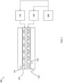
- FIG 1 illustrates a top view of an embodiment of a compression ignition engine 100, e.g. a Diesel engine, comprising six cylinders 101 in an inline configuration.
- the compression ignition engine 100 may comprise any other number of cylinders, e.g. three, four, eight or twelve, arranged in any other cylinder configuration and in one or more cylinder banks, e.g. in a line, in a V, or horizontally opposed.
- the ignition compression engine 100 may be a straight-six, a V8, or a flat-four.
- Each cylinder 101 comprises one or more intake valves 111 for intaking air into the cylinder 101, e.g. via an intake manifold and air filter, and one or more exhaust valves 112 for discharging exhaust gas from the cylinder 101, e.g. into an exhaust manifold and exhaust line.
- the engine 100 comprises a turbocompressor to boost pressure in the intake manifold, and/or an EGR system to recirculate exhaust gases into the cylinders.
- a valve actuation system 110 is arranged for opening and closing the one or more intake valves 111 and exhaust valves 112 of each cylinder 101, e.g. via a cam shaft.
- the valve actuation system 110 may be a variable valve actuation system, e.g. comprising electronically controllable valve actuators, to allow timing adjustment of opening and closing the intake valves and exhaust valves.
- a fuel injection system 120 e.g. comprising a fuel rail and a plurality of fuel injectors, is arranged for injecting fuel into a combustion chamber of each cylinder.
- the compression ignition engine may be operated, by a controller 200, such that each cylinder is arranged for conducting a four-stroke Miller cycle.
- the intake valve is generally left open longer than it would be in a normal Diesel -cycle engine.
- the compression stroke is two discrete cycles: the initial portion when the intake valve is open and final portion when the intake valve is closed. This two-stage compression stroke creates the so-called "fifth" stroke that the Miller cycle introduces.
- the Miller cycle for example comprises:
- the valve actuation system 110 is controlled, e.g. by the controller 200, to have the one or more intake valves 111 in an open position and the one or more exhaust valves 112 in a closed position, to discharge a first portion of the air from the combustion chamber through the one or more intake valves, e.g. back into the intake manifold.
- the discharge stage ends between 30 and 60 degrees crank angle from BDC, preferably between 40 and 50 degrees crank angle from BDC. Delaying the closing of intake valves in the Miller cycle in effect shortens the compression stroke compared to the expansion stroke. This allows the gases to be expanded to atmospheric pressure, increasing the efficiency of the cycle.
- the piston In the subsequent compression stage, the remaining second portion of the air inside the exhaust chamber is compressed as the piston moves toward TDC by controlling the valve actuation system 110, e.g. by the controller 200, to have the one or more intake valves 111 and the one or more exhaust valves 112 in a closed position.
- the piston In effect, in the Miller-cycle engine, the piston begins compression only after the one or more intake valves close, and the intake valves are closed after the piston has travelled a certain distance beyond BDC, e.g. around 20 to 30% of the total piston travel towards TDC. So in the Miller cycle engine, the piston actually compresses the air mixture only during the latter 70% to 80% of the compression stroke. During the initial part of the compression stroke, the piston pushes part of the fuel-air mixture through the still-open intake valve, and back into the intake manifold.
- a power stroke sometimes called expansion stroke, for powering the engine.
- the fuel injection system 120 is controlled, e.g. by the controller 200, to start injecting a main fuel injection into the pressurized combustion chamber. Due to the in-cylinder pressure and temperature the air-fuel mixture in the combustion chamber ignites.
- the valve actuation system 110 is controlled, e.g. by the controller 200, to have the one or more intake and exhaust valves 111, 112 in a closed position. The igniting air-fuel mixture expands and pushes the piston downward, toward BDC.
- the four stroke Miller cycle may comprise (iv) an exhaust stroke, in which the valve actuation system is controlled, e.g. by the controller 200, to have the one or more intake valves 111 in a closed position and the one or more exhaust valves 112 in an open position, to discharge exhaust gas from the combustion chamber through the exhaust valve as the piston moves from BDC towards TDC.
- the shortened compression stroke compared to the expansion stroke results in an increased efficiency of the engine.
- the reduced in-cylinder pressure and temperature caused by the Miller cycle creates a loss of power compared to a standard Diesel cycle.
- this loss can be compensated for by the use of a (VTG) turbocompressor.
- the VTG turbocompressor may be calibrated to supply the same mass air flow as a standard Diesel cycle engine has, by increasing the boost pressure.
- the higher temperature of the compressed air supplied by the turbocompressor can be reduced by an intercooler before it enters the cylinders. Result is that despite the shorter compression stroke, the amount and temperature of the air in the cylinder is the same as in the standard Diesel cycle.
- the Miller cycle provides an improved fuel efficiency by having a longer expansion stroke with respect to the compression stroke, without reducing power of the engine.
- the turbocompressor is not effective yet, so the reduced mass in the cylinder cannot be compensated, thereby attenuating the benefits of the Miller cycle
- the controller 200 is arranged for operating the compression ignition engine in a normal mode or a cold start mode.
- the controller 200 is arranged for controlling the fuel injection system 120 to inject the main fuel injection in a single pulse, e.g. between 3.5 degrees crank angle before TDC and 4.5 degrees crank angle after TDC.
- the main injection is intended to start the diffusion-combustion phase in the power stroke to power the engine.
- the normal mode may comprise a pilot injection preceding the main fuel injection to premix the incoming air with fuel.
- the pilot injection may have a fuel quantity between 7.5% and 17.5% of the fuel quantity of the main fuel injection
- the controller 200 may be arranged for controlling the fuel injection system 120 to start injecting the pilot injection between 27 and 1.5 degrees crank angle before the start of the main fuel injection.
- the normal mode may comprise a late or post fuel injection following the main fuel injection for thermal management and emission reduction.
- the normal mode is active during operating conditions in which the ambient temperature is higher than 0, 5 or 10 degrees Celsius, and in which ambient pressure is about 100 kPa.
- the normal mode may be activated after the engine is started, thus when the engine is running at idle speed or higher, which case by case may be dependent on e.g. the size and type of engine, engine load, and ambient conditions.
- the idle speed may be around 550 RPM, e.g. between 500 and 600 RPM, while for passenger vehicle engines the idle speed may be around 1000 RPM, e.g. between 800-1000 RPM.
- the controller 200 is arranged for operating the compression ignition engine in the cold start mode when the ambient and/or coolant temperature is below a temperature threshold value, e.g. lower than 10, 5, 0, -5 or -10 degrees Celsius and/or when the ambient pressure is below a pressure threshold value, e.g. lower than 95, 90, 85 or 80 kPa, e.g. down to 60 kPa.
- a temperature threshold value e.g. lower than 10 degrees Celsius
- a pressure threshold value e.g. lower than 95, 90, 85 or 80 kPa, e.g. down to 60 kPa.
- the controller 200 is arranged for splitting the main fuel injection into a first split main and a second split main, and for controlling the fuel injection system 120 to inject the first and second split main in two distinct pulses. This can e.g.
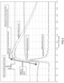
- FIG 2 provides a graph of crank angle based in-cylinder pressure data at -15 °C and 100kPa, for a Miller cycle compression ignition engine in the cold start mode (black) and in the normal mode (blue). It is clear from FIG 2 that, in such ambient conditions, the cold start mode provides higher in-cylinder pressure in the power stroke, thus improving starting behaviour of the engine.
- the first split main has a fuel quantity between 75% and 98% of the fuel quantity of the main fuel injection, e.g. between 80% and 95%
- the controller 200 is arranged for controlling the fuel injection system to inject the first split main at a delayed timing between TDC and 4.5 degrees crank angle after TDC.
- a delayed timing ensures that the diffusion combustion phase is initialized after TDC, to improve the starting behaviour of the engine.
- the second split main preferably has a fuel quantity of 2-25% of the fuel quantity of the main fuel injection, e.g. between 5-20%, and the controller 200 is arranged for controlling the fuel injection system 120 to start injecting the second split main between 0.5 and 7 degrees crank angle after an end of the first split main, preferably between 1.5 and 5 degrees crank angle after the end of the first split main.
- the first and second split main pulse are distinct, e.g. separated, from each other.
- the controller 200 may be arranged for calculating and calibrating the start and end of the first split main pulse with respect to TDC, and for calculating and calibrating the start and end of the second split main pulse with respect to an end of the first split main pulse, to control the respective injected fuel quantities and timings.
- the cold start mode may also additionally comprise a pilot injection and/or a late or post fuel injection, which are thus not part of the (first and second) main injection pulse described herein.
- the main fuel injection is split into two parts: (A) the first split main, and (B) the second split main.
- Any fuel injection(s) performed before or after the main injection, such as pilot, post, or late injections, are not referred to as a split main pulse and may be entirely optional to the general concept of the invention.
- a pilot injection is considered to occur substantially before the main injection.
- a post or late injection is considered to occur after the end of the diffusion combustion phase, e.g. during the tail phase in which the in-cylinder pressure is decreasing.
- the first split main pulse is injected after TDC to initiate a diffusion combustion phase
- the second split main pulse is injected during the diffusion combustion phase while in-cylinder pressure is still increasing, e.g. as illustrated in FIG 2 .
- the fuel quantity of the first split main and the fuel quantity of the second split main add up to the fuel quantity of the main fuel injection.
- the first and second split main are injected into the combustion chamber by two distinct (e.g. separate or intermittent) pulses.
- the first split main is injected for initiating diffusion combustion in the pressurized combustion chamber, and the second split main is injected during the diffusion combustion phase into the already combusting air-fuel mix.
- the cold start behaviour of the engine e.g. at low ambient temperatures and/or pressures
- the main fuel injection is split.
- the main injection pulse is reduced by a certain amount, e.g. by 5-25%, which amount is introduced later in the combustion cycle during the diffusion-combustion-phase when the combustion is already in progress.
- the ignition delay is reduced (with reference to TDC) since the first split main pulse ends earlier than the single main fuel injection pulse, which causes the heat-release to occur closer to (yet still after) TDC, which is desirable for flame propagation and indicated mean effective pressure (IMEP).
- IMEP mean effective pressure
- the distinct second split main allows for a pseudo-diffusion phase combustion where the remaining amount of fuel (5-25%) is injected in the already combusting air-fuel mix. This causes a higher IMEP overall, leading to better cold start performance, e.g. as illustrated in FIG 2 .
- split-main injection described herein can be regarded as an ignition delay reduction as well as an IMEP increase aid.
- Such a split-main injection strategy is not only applicable to Miller cold starts at altitude but also at sea-level ambient pressures, e.g. around 100kPa.
- the controller may be arranged for switching between the normal mode and the cold start mode based on an actual ambient temperature, an actual coolant temperature, and/or an actual ambient pressure.
- the actual ambient or coolant temperature and pressure may be measured, e.g. by sensors on board a vehicle comprising the compression ignition engine, or obtained from an external source based on geolocation of the vehicle.
- the controller 200 when the actual ambient or coolant temperature and/or pressure is below a predetermined minimum value, the controller 200, in use, selects the cold start mode. Otherwise, in case the actual ambient or coolant temperature and/or pressure is higher than the predetermined minimum value, the normal mode is selected.
- the minimum value can e.g. be pre-programmed or obtainable from a look up table.
- the controller 200 may be arranged for switching between the normal mode and the cold start mode in response to an actual compression pressure in the cylinder, e.g. measured by a pressure sensor.
- the compression pressure of a compression ignition engine can vary depending on the specific engine and its design. However, in general, Diesel engines may have compression pressures ranging from 150 to 300 bar. In a compression ignition engine, the compression temperature of air can be about 500-600 degree Celsius. The compression pressure needs to be high to have efficient combustion to take place and avoid any ignition lag. Generally, the compression pressure is reduced by operating a Miller cycle on an engine.
- Compression pressure and temperature can be used as an indicator for switching between the normal mode and the cold start mode. For example, in case the compression pressure and/or compression temperature is below a threshold, the controller 200, in use, may switch from the normal mode to the cold start mode. Conversely, when the compression pressure and/or compression temperature exceeds a threshold, the controller 200 may switch from the cold start mode to the normal mode.
- the controller may be arranged for switching between the normal mode and the cold start mode in response to an average in-cylinder pressure, e.g. calculated over one or more combustion cycles per cylinder.
- an indication of the work performed by each cylinder can be obtained, and, in use, the controller for example switches from the normal mode to the cold start mode when the average in-cylinder pressure is below a threshold, and switches vice versa when the average in-cylinder pressure is higher than a threshold.
- FIG 3 illustrates an embodiment of a commercial vehicle, such as a truck, bus, touring car, heavy duty vehicle or passenger car.
- the commercial vehicle 10 comprises a compression ignition engine 100 described herein.
- the cold start behaviour of the commercial vehicle is improved, e.g. allowing the commercial vehicle to start more rapidly in relatively cold ambient temperatures, e.g. below 10 degrees Celsius, and/or at relatively high altitudes where the air is thin, e.g. ambient pressures below 95 kPa.
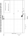
- cold starting performance is improved by the split main fuel injection strategy of the cold start mode described herein (open circles) in comparison with the normal mode (closed circles), especially in relatively cold ambient conditions.
- FIG 5 illustrates an embodiment of a method 1000 for improving cold start behaviour of a compression ignition engine comprising a plurality of cylinders, a valve actuation system arranged for opening and closing intake valves and exhaust valves of each cylinder of said plurality of cylinders, and a fuel injection system arranged for injecting fuel into a combustion chamber of each cylinder.
- each cylinder of the plurality of cylinders is arranged for conducting a four-stroke Miller cycle as described herein.
- the method 1000 comprises the following steps.
- Step 1001 selecting a normal mode or a cold start mode for operating the compression ignition engine.
- Step 1002 in the normal mode, controlling the fuel injection system to inject the main fuel injection in a single pulse.
- Step 1003 in the cold start mode, splitting the reduced main fuel injection into a first split main and a second split main (1003a), and controlling the fuel injection system to inject the first and second split main in two distinct pulses, wherein the first split main is injected at a delayed timing for initiating a diffusion combustion phase in the pressurized combustion chamber, and wherein the second split main is injected during the diffusion combustion phase into the already combusting air-fuel mix (1003b).
Landscapes
- Engineering & Computer Science (AREA)
- Chemical & Material Sciences (AREA)
- Combustion & Propulsion (AREA)
- Mechanical Engineering (AREA)
- General Engineering & Computer Science (AREA)
- Electrical Control Of Air Or Fuel Supplied To Internal-Combustion Engine (AREA)
Applications Claiming Priority (1)
| Application Number | Priority Date | Filing Date | Title |
|---|---|---|---|
| NL2035587A NL2035587B1 (en) | 2023-08-10 | 2023-08-10 | Compression ignition engine, commercial vehicle, and method for improving starting behaviour |
Publications (1)
| Publication Number | Publication Date |
|---|---|
| EP4506553A1 true EP4506553A1 (de) | 2025-02-12 |
Family
ID=87974405
Family Applications (1)
| Application Number | Title | Priority Date | Filing Date |
|---|---|---|---|
| EP24193864.6A Pending EP4506553A1 (de) | 2023-08-10 | 2024-08-09 | Kompressionszündungsmotor, nutzfahrzeug und verfahren zur verbesserung des startverhaltens |
Country Status (3)
| Country | Link |
|---|---|
| US (1) | US12416273B2 (de) |
| EP (1) | EP4506553A1 (de) |
| NL (1) | NL2035587B1 (de) |
Citations (6)
| Publication number | Priority date | Publication date | Assignee | Title |
|---|---|---|---|---|
| DE102004053748A1 (de) * | 2004-11-06 | 2006-05-24 | Bayerische Motoren Werke Ag | Verfahren für den Betrieb einer selbstzündenden Brennkraftmaschine |
| US20060272608A1 (en) * | 2005-06-07 | 2006-12-07 | Hitachi, Ltd. | Compression ignition engine |
| US7207311B2 (en) * | 2002-10-22 | 2007-04-24 | Avl List Gmbh | Method for operating a direct injection diesel engine |
| DE102016015251A1 (de) * | 2015-12-24 | 2017-06-29 | Mazda Motor Corporation | Verfahren zur Steuerung von Kraftstoffeinspritzung und Vorrichtung zur Steuerung von Kraftstoffeinspritzung für einen Selbstzündungsmotor |
| US20180195457A1 (en) * | 2017-01-12 | 2018-07-12 | Toyota Jidosha Kabushiki Kaisha | Control device of internal combustion engine |
| US20230129315A1 (en) * | 2019-05-15 | 2023-04-27 | Clearflame Engines, Inc. | Cold Start for High-Octane Fuels in a Diesel Engine Architecture |
Family Cites Families (14)
| Publication number | Priority date | Publication date | Assignee | Title |
|---|---|---|---|---|
| JP5056982B2 (ja) * | 2010-03-11 | 2012-10-24 | トヨタ自動車株式会社 | 内燃機関の制御装置 |
| JP4924751B1 (ja) | 2010-11-09 | 2012-04-25 | マツダ株式会社 | 火花点火式直噴エンジンの制御方法及びその制御装置 |
| DE102011083033A1 (de) | 2011-09-20 | 2013-03-21 | Robert Bosch Gmbh | Verfahren zur Beurteilung eines Einspritzverhaltens wenigstens eines Einspritzventils einer Brennkraftmaschine und Betriebsverfahren für Brennkraftmaschine |
| US10100767B2 (en) * | 2015-06-08 | 2018-10-16 | Ford Global Technologies, Llc | Method and system for engine cold-start control |
| US9903307B2 (en) | 2016-01-04 | 2018-02-27 | Ford Global Technologies, Llc | Method of fuel injection control |
| KR101807042B1 (ko) | 2016-05-24 | 2018-01-10 | 현대자동차 주식회사 | 가솔린-디젤 혼합 연소 엔진의 제어 장치 및 방법 |
| JP6414156B2 (ja) | 2016-07-22 | 2018-10-31 | トヨタ自動車株式会社 | 内燃機関の制御装置 |
| FR3072424B1 (fr) | 2017-10-16 | 2022-04-08 | Continental Automotive France | Procede de compensation de combustion degradee due a un ecart de pression de carburant reelle |
| JP6915577B2 (ja) | 2018-04-03 | 2021-08-04 | トヨタ自動車株式会社 | 内燃機関の制御装置 |
| JP6975890B2 (ja) | 2018-04-09 | 2021-12-01 | 株式会社豊田自動織機 | 内燃機関の制御装置 |
| JP7155678B2 (ja) | 2018-07-06 | 2022-10-19 | マツダ株式会社 | ディーゼルエンジンの燃料噴射制御装置 |
| WO2020046694A1 (en) | 2018-08-29 | 2020-03-05 | Tula Technology, Inc. | Split direct injection for reactivated cylinders of an internal combustion engine |
| JP7167831B2 (ja) * | 2019-04-19 | 2022-11-09 | マツダ株式会社 | 圧縮着火式エンジンの制御装置 |
| KR20210099392A (ko) | 2020-02-04 | 2021-08-12 | 현대자동차주식회사 | 냉시동 분할분사제어 방법 및 엔진 시스템 |
-
2023
- 2023-08-10 NL NL2035587A patent/NL2035587B1/en active
-
2024
- 2024-08-09 US US18/798,884 patent/US12416273B2/en active Active
- 2024-08-09 EP EP24193864.6A patent/EP4506553A1/de active Pending
Patent Citations (6)
| Publication number | Priority date | Publication date | Assignee | Title |
|---|---|---|---|---|
| US7207311B2 (en) * | 2002-10-22 | 2007-04-24 | Avl List Gmbh | Method for operating a direct injection diesel engine |
| DE102004053748A1 (de) * | 2004-11-06 | 2006-05-24 | Bayerische Motoren Werke Ag | Verfahren für den Betrieb einer selbstzündenden Brennkraftmaschine |
| US20060272608A1 (en) * | 2005-06-07 | 2006-12-07 | Hitachi, Ltd. | Compression ignition engine |
| DE102016015251A1 (de) * | 2015-12-24 | 2017-06-29 | Mazda Motor Corporation | Verfahren zur Steuerung von Kraftstoffeinspritzung und Vorrichtung zur Steuerung von Kraftstoffeinspritzung für einen Selbstzündungsmotor |
| US20180195457A1 (en) * | 2017-01-12 | 2018-07-12 | Toyota Jidosha Kabushiki Kaisha | Control device of internal combustion engine |
| US20230129315A1 (en) * | 2019-05-15 | 2023-04-27 | Clearflame Engines, Inc. | Cold Start for High-Octane Fuels in a Diesel Engine Architecture |
Also Published As
| Publication number | Publication date |
|---|---|
| US12416273B2 (en) | 2025-09-16 |
| US20250052209A1 (en) | 2025-02-13 |
| NL2035587B1 (en) | 2025-02-24 |
Similar Documents
| Publication | Publication Date | Title |
|---|---|---|
| US9702316B2 (en) | Spark-ignition direct injection engine | |
| US9376967B2 (en) | Auto-ignition internal combustion engine with partial deactivation and method for the operation of an internal combustion engine of said type | |
| US9255539B2 (en) | Spark-ignition direct injection engine | |
| US8156920B2 (en) | Procedure for the operation of an internal combustion engine | |
| US9261041B2 (en) | Spark-ignition direct injection engine | |
| US7703442B2 (en) | Method for operating an internal combustion engine | |
| US7680584B2 (en) | Procedure for the operation of an internal combustion engine | |
| US7640911B2 (en) | Two-stroke, homogeneous charge, spark-ignition engine | |
| JP2014051936A (ja) | 火花点火式直噴エンジン | |
| US7992541B2 (en) | System and method for controlling auto-ignition | |
| US20050252464A1 (en) | Control device of charge compression ignition-type internal combustion engine | |
| JP2012246784A (ja) | 火花点火式エンジンの制御装置 | |
| JP2007177792A (ja) | 圧縮比変更機構を備えた内燃機関および内燃機関の制御方法 | |
| JP2004308618A (ja) | 圧縮比変更機構を備えた内燃機関および内燃機関の制御方法 | |
| US10337427B2 (en) | Control device of compression self-ignition engine | |
| CN108884804A (zh) | 内燃机控制装置 | |
| JP2014051935A (ja) | 火花点火式直噴エンジン | |
| EP4506553A1 (de) | Kompressionszündungsmotor, nutzfahrzeug und verfahren zur verbesserung des startverhaltens | |
| US7788016B2 (en) | Method for operating an internal combustion engine | |
| US11492987B2 (en) | Cylinder charge trapping strategies based on predictive number of skips and staggered implementation of valvetrain dependent operational strategies for internal combustion engines | |
| US20090301434A1 (en) | Method for operating an internal combustion engine | |
| JP2004346854A (ja) | 内燃機関の圧縮着火運転の制御装置 | |
| JP2018096311A (ja) | 内燃機関の制御装置 | |
| US7917280B2 (en) | Method and device for operating an internal combustion engine | |
| JP4120452B2 (ja) | 筒内噴射式内燃機関 |
Legal Events
| Date | Code | Title | Description |
|---|---|---|---|
| PUAI | Public reference made under article 153(3) epc to a published international application that has entered the european phase |
Free format text: ORIGINAL CODE: 0009012 |
|
| STAA | Information on the status of an ep patent application or granted ep patent |
Free format text: STATUS: REQUEST FOR EXAMINATION WAS MADE |
|
| 17P | Request for examination filed |
Effective date: 20240809 |
|
| AK | Designated contracting states |
Kind code of ref document: A1 Designated state(s): AL AT BE BG CH CY CZ DE DK EE ES FI FR GB GR HR HU IE IS IT LI LT LU LV MC ME MK MT NL NO PL PT RO RS SE SI SK SM TR |