EP4506811A1 - Procédé de mise à jour d'une version logicielle pour une fonction de commande d'un agencement de circuit pour commander une machine au moyen de l'agencement de circuit, produit de programme informatique et agencements de circuit - Google Patents
Procédé de mise à jour d'une version logicielle pour une fonction de commande d'un agencement de circuit pour commander une machine au moyen de l'agencement de circuit, produit de programme informatique et agencements de circuit Download PDFInfo
- Publication number
- EP4506811A1 EP4506811A1 EP23191113.2A EP23191113A EP4506811A1 EP 4506811 A1 EP4506811 A1 EP 4506811A1 EP 23191113 A EP23191113 A EP 23191113A EP 4506811 A1 EP4506811 A1 EP 4506811A1
- Authority
- EP
- European Patent Office
- Prior art keywords
- electronic computing
- computing device
- data sensor
- software version
- control function
- Prior art date
- Legal status (The legal status is an assumption and is not a legal conclusion. Google has not performed a legal analysis and makes no representation as to the accuracy of the status listed.)
- Pending
Links
Images
Classifications
-
- G—PHYSICS
- G06—COMPUTING OR CALCULATING; COUNTING
- G06F—ELECTRIC DIGITAL DATA PROCESSING
- G06F11/00—Error detection; Error correction; Monitoring
- G06F11/07—Responding to the occurrence of a fault, e.g. fault tolerance
- G06F11/14—Error detection or correction of the data by redundancy in operations
- G06F11/1402—Saving, restoring, recovering or retrying
- G06F11/1415—Saving, restoring, recovering or retrying at system level
- G06F11/1433—Saving, restoring, recovering or retrying at system level during software upgrading
-
- G—PHYSICS
- G06—COMPUTING OR CALCULATING; COUNTING
- G06F—ELECTRIC DIGITAL DATA PROCESSING
- G06F8/00—Arrangements for software engineering
- G06F8/60—Software deployment
- G06F8/65—Updates
- G06F8/656—Updates while running
Definitions
- the invention relates to a method for updating a software version for a control function for a circuit arrangement for controlling a machine by means of the circuit arrangement according to the applicable patent claim 1. Furthermore, the invention relates to a computer program product, a corresponding computer-readable storage medium and a circuit arrangement.
- the object of the present invention is to provide a method, a computer program product, a computer-readable storage medium and a circuit arrangement by means of which a software version for a control function for the circuit arrangement can be updated with reduced effort.
- One aspect of the invention relates to a method for updating a software version for a control function for a circuit arrangement for controlling a machine by means of the circuit arrangement.
- a data packet for updating the software version is received by means of a receiving device of the circuit arrangement.
- the data packet is stored in a first memory device of a first electronic computing device of the circuit arrangement and the data packet is stored in a second memory device of a second electronic computing device of the circuit arrangement.
- the first electronic computing device is expanded with a further external data sensor and the second electronic computing device is expanded with a still further external data sensor and the software version is released for updating by means of the further external data sensor and the yet further external data sensor.
- the software version on the second electronic computing device is updated depending on the release of the yet further external data sensor.
- the software version is updated, in particular subsequently, on the first electronic computing device depending on the release of the further data sensor.
- the control of the machine is guaranteed during the entire software version update phase, or at least an emergency function is provided for the machine, so that a safe system state can be achieved in the event of a fault.
- the first electronic computing device and the second electronic computing device are identical but designed separately from one another.
- the circuit arrangement enables the use of highly available and/or safety-critical control systems.
- a special feature of this approach is that no dedicated special hardware is required for a fail-safe PLC (programmable logic controller). Instead, standard industrial hardware can be used as an electronic computing device for executing safety-relevant control functions, which can be upgraded accordingly without the control function, let alone the control system contained therein, having to be stopped.
- PLC programmable logic controller
- a control function is used and executed by two, in particular analog, control function instances that are deployed and executed on respective computing nodes/electronic computing devices. Since these are two instances of a control function, the two electronic computing devices behave identically if everything else remains unchanged.
- External data sensors are interleaved with internal data sensors and in particular with the corresponding electronic computing devices. These data sensors form the backbone of the circuit arrangement with two redundant safety connections to control the safety device.
- the circuitry detects and handles failing or faulty processes, process communication links and computing nodes.
- the circuit arrangement is fully functional in order to completely cover the life cycle of the safety-relevant control instance, including upgrades and downgrades of the control function with internal data sensors and the external data sensors.
- the circuit arrangement outlasts the control function instances, i.e. the circuit arrangement before and after the control function instances is preferably still operational.
- safety-relevant control functions can be carried out by executing them using inexpensive hardware, for example industrial standard hardware, rather than on dedicated, comparatively expensive hardware, such as a fail-safe PLC.
- PLCs are difficult to obtain, which allows for faster provision of the circuitry.
- the redundant external data sensors which run in separate processes on redundant standard industrial hardware, which is different from the hardware on which the monitored, safety-relevant control function runs, thus implement an independent network in a cost-effective manner.
- the circuit arrangement enables a seamless upgrade of highly available, safety-relevant control functions on standard industrial hardware.
- the invention thus enables the seamless upgrade of highly available, safety-relevant control functions.
- Parallel substitutions, in particular upgrades or downgrades, of redundant control function instances can be carried out on the two electronic computing devices. In particular, it is ensured that at any time, even during an update of control functions in the ongoing operation, a safe system response can be guaranteed.
- the first electronic computing device is provided as the primary control device for the machine.
- corresponding communication between the first electronic computing device and the machine is thus active.
- a connection between the second electronic computing device and the machine can be considered inactive.
- the control of the machine is carried out via the first electronic computing device.
- the circuit arrangement is designed so that, if, for example, an error occurs in the first electronic computing device, the connection between the first electronic computing device and the machine is then switched to inactive and the control function is carried out via the second electronic computing device.
- a redundant system can thus be created for the machine and the probability of failure of the machine can be reduced.
- the control of the machine by means of the second electronic computing device is carried out.
- the second electronic computing device thus serves as a fallback level should an error be detected.
- the control function can also be taken over by the second electronic computing device, which enables the machine to be operated safely.
- the data packet is checked by the first electronic computing device and/or the second electronic computing device using a respective data sensor before the data packet is updated.
- so-called pre-activation tests are carried out on the redundant electronic computing devices with regard to the new version before the update via the circuit device.
- the current version of the control function is still available and ready to take over control immediately.
- These tests before activation are in particular basic checks, e.g. whether installations and setups have been carried out correctly, whether the components required for a control function version, in particular other control functions and communication connections, are present and function as expected, and whether the inputs of the control functions have the expected properties.
- test results before activation of both redundant control function instances must in particular be the same before a new control function version, which in particular corresponds to the software version, can be activated, i.e. before one of their redundant control function instances can become the new primary.
- a continuous, flowing upgrade of a redundant control function is carried out. This means that it is possible to check before the actual update whether any errors could occur during the update. This reduces the probability of the machine failing.
- the software version can also be an update of the data sensors and/or test programs. This has the advantage, for example, that storage space can be freed up for a future software version. This can reduce storage requirements.
- Another advantageous embodiment provides that after updating the software version, the previously installed software version is saved as a fallback version by the first electronic computing device and/or second electronic computing device.
- the previously installed software version continues to be saved. If problems arise with the new software version or updated software version, the functional previously installed version can be used. This can prevent system failures in the machine.
- a first control function for controlling the machine is monitored by means of an internal first data sensor of the first electronic computing device and by means of an external first data sensor of the second electronic computing device.
- This makes it possible for independent electronic computing devices to carry out a respective check of the other electronic computing device. This prevents, for example, a failure of the control function for the machine if an entire electronic computing device fails. This means that monitoring of the electronic computing device can also be implemented during the update process.
- a second control function for controlling the machine is monitored by means of an internal second data sensor of the second electronic computing device and by means of an external second data sensor of the first electronic computing device.
- This makes it possible for a respective check of the other electronic computing device to be carried out on independent electronic computing devices.
- This prevents, for example, a failure of the control function for the machine in the event of a failure of an entire electronic computing device.
- monitoring of the electronic computing device can also be implemented during the update process.
- the external first data sensor and the external second data sensor are coupled to one another via a communication connection.
- the electronic computing devices can thus exchange their control functions, for example.
- a system control logic can thus be implemented in the individual electronic computing devices with an activated control function coordination connection. In this way, reliable operation of the machine can be implemented.
- a further advantageous embodiment provides that the first electronic computing device and the second electronic computing device are coupled to one another via a further communication connection.
- the external data sensors can thus compare their system views and detect system inconsistencies or component failures in the event of failure of the data sensors and/or failure of the communication connections.
- the circuit arrangement can switch to the second electronic computing device or, as a last resort, trigger the corresponding safety device via the emergency connection. This enables safe operation of the machine.
- an emergency control for the machine is carried out using one of the data sensors depending on an event. If, for example, an event occurs, even during the software update, a corresponding emergency control of the machine can still be carried out. In particular, at least the emergency control, for example an emergency stop of the machine, can thus be implemented even during the update.
- the circuit arrangement can therefore be used in safety-relevant areas. Emergency control of the machine is thus ensured.
- a further aspect of the invention relates to a computer program product with program code means which cause at least one electronic computing device to carry out a method according to the previous aspect when the program code means are processed by the at least one electronic computing device.
- the invention also relates to a computer-readable storage medium with a computer program product according to the preceding aspect.
- Yet another aspect of the invention relates to a circuit arrangement for updating a software version and for controlling a machine, with at least a first electronic computing device and a second electronic computing device, wherein the circuit arrangement is designed to carry out a method according to the preceding aspect.
- the method is carried out by means of the circuit arrangement.
- the invention relates to a machine system with at least one machine, a safety device and a circuit arrangement for controlling the machine, according to the preceding aspect.
- Advantageous embodiments of the method are to be regarded as advantageous embodiments of the circuit arrangement of the machine system.
- the circuit arrangement and the machine system in particular have material features in order to be able to carry out corresponding method steps.
- a computing unit/electronic computing device can be understood in particular as a data processing device that contains a processing circuit.
- the computing unit can therefore in particular process data to carry out computing operations. This may also include operations to carry out indexed access to a data structure, for example a conversion table, LUT (English: "look-up table").
- the computing unit can in particular contain one or more computers, one or more microcontrollers and/or one or more integrated circuits, for example one or more application-specific integrated circuits (ASICs), one or more field-programmable gate arrays (FPGAs), and/or one or more single-chip systems (SoCs).
- the computing unit can also contain one or more processors, for example one or more microprocessors, one or more central processing units (CPUs), one or more graphics processing units (GPUs) and/or one or more signal processors, in particular one or more digital signal processors (DSPs).
- the computing unit can also contain a physical or virtual network of computers or other of the aforementioned units.
- the computing unit includes one or more hardware and/or software interfaces and/or one or more memory units.
- a memory unit can be a volatile data storage device, such as a dynamic random access memory (DRAM) or a static random access memory (SRAM), or a non-volatile data storage device, such as a read-only memory (ROM), a programmable read-only memory (PROM), an erasable programmable read-only memory (EPROM), an electrically erasable programmable read-only memory (EEPROM), a flash memory or flash EEPROM, a ferroelectric random access memory (FRAM), a magnetoresistive random access memory (MRAM) or a Phase-change random access memory (PCRAM).
- DRAM dynamic random access memory
- SRAM static random access memory
- ROM read-only memory
- PROM programmable read-only memory
- EPROM erasable programmable read-only memory
- EEPROM electrically erasable programmable read-only memory
- flash memory or flash EEPROM a ferroelectric random access memory (FRAM), a magnetoresistive random access memory (MRAM
- an error message and/or a request to enter user feedback is issued and/or a default setting and/or a predetermined initial state is set.
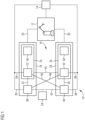
- FIG 1 shows a schematic block diagram of an embodiment of a machine system 10.
- the machine system 10 has at least one machine 12, a safety device 14 and a circuit arrangement 16.
- the circuit arrangement 16 is designed to control the machine 12.
- the circuit arrangement 16 has at least one first electronic computing device 18 for generating a first control signal 20 for the machine 12.
- the first electronic computing device 18 has an internal first data sensor 22, in particular for a first control function 24 for generating the control signal 20.
- the first internal data sensor 22 is designed to generate a first safety signal 26 for the safety device 14.
- the circuit arrangement 16 has a second electronic computing device 28 which is designed to generate a second control signal 30 for the machine 12, wherein the second electronic computing device 28 has an internal second data sensor 32, in particular for a second control function 34, and for generating a second safety signal 36 for the safety device 14, wherein the first electronic computing device 18 has an external second data sensor 38 which is coupled to the internal second data sensor 32 and wherein the second electronic computing device 28 has an external first data sensor 40 which is coupled to the internal first data sensor 22, and wherein a respective safety signal 26, 36 can additionally be generated by the external first data sensor 40 and/or the external second data sensor 38.
- FIG 1 also that the first external data sensor 40 and the external second data sensor 38 are coupled to one another via a communication connection 42. Furthermore, the first electronic computing device 18 and the second electronic computing device 28 can be coupled to one another via a further communication connection 44. Furthermore, the FIG 1 that the external second data sensor 38 is coupled to the internal second data sensor 32 via a first communication link 46 and the external first data sensor 40 is coupled to the internal first data sensor 22 is coupled via a further communication link 48. Furthermore, connections 50 and 52 are shown, which connect the respective internal data sensors 22, 32 with the external data sensors 38, 40.
- the first electronic computing device 18 is designed as a primary control device for the machine 12.
- the internal first data sensor 22 is designed in particular to monitor the operation of the first electronic computing device 18 and/or the internal second data sensor 32 is designed to monitor the operation of the second electronic computing device 28.
- the external second data sensor 38 can be designed to monitor the operation of the first electronic computing device 18 and/or the external first data sensor 40 can be designed to monitor the operation of the second electronic computing device 28.
- the data sensors 22, 32, 38, 40 are designed to carry out a test program for the first electronic computing device 18 and/or the second electronic computing device 28.
- FIG 1 that a control function 24, 34 is used and executed by the first electronic computing device 18 and/or by the second electronic computing device 28. Since these are two instances of the control function 24, 34, the first electronic computing device 18 and the second electronic computing device 28 behave essentially identically if everything else remains unchanged.
- the first electronic computing device 18 can be designed as a primary control instance.
- the primary control instance controls the environment of the control functions 24, 34 to the machine via a corresponding actuator connection that is active.
- the secondary control instance in this case in particular the second electronic computing device 28, is inactive. Only the respective connection of the primary part can be active at any one time. Under special conditions, the corresponding connection of the primary component can become inactive.
- the external data sensors 38, 40 are interleaved with the respective internal data sensors 22, 32. These data sensors 22, 32, 38, 40 in turn form the so-called backbone of a distributed safety monitor, as corresponds in particular to the circuit arrangement 16, with the two redundant emergency connections to the safety device 14.
- the circuit arrangement 16 detects and handles failures or faulty processes, process communication connections and computing nodes.
- the circuit arrangement 16 has redundant and independent internal data sensors 22, 32, which are particularly built into the electronic computing devices 18, 28 and are implemented there.
- the circuit arrangement 16 also has redundant and independent external data sensors 38, 40, which are implemented as separate, autonomous, pure sensor processes.
- the external second data sensor 38 can be interleaved with the internal first data sensor 22, and the external first data sensor 40 with the internal second data sensor 32, particularly laterally, i.e. on the same electronic computing device 18, 28 and also between the various independent electronic computing devices 18, 28.
- the data sensors 22, 32, 38, 40 are particularly interleaved with one another in such a way as to exchange their monitoring function and to monitor one another, for example in order to to monitor and compare the availability and health status of the peer, similar to how the electronic computing devices 18, 28 monitor each other. Furthermore, the corresponding emergency connections to the security device 14 are provided.
- the internal data sensors 22, 32 monitor the operation of the electronic computing devices 18, 28 by monitoring and changing data elements relating to the control function instances or their resources from case to case.
- the internal data sensors 22, 32 implement test programs in particular.
- the external data sensors 38, 40 can also implement test programs, but in dedicated, independent monitoring processes on different electronic computing devices 18, 28.
- the external first data sensor 40 in turn monitors the first control function 24 and the external second data sensor 38 monitors the second control function 34. This monitoring is in turn carried out via the corresponding internal data sensors 22, 32.
- the first control function 24 is monitored by means of the external first data sensor 40 via the first internal data sensor 22
- the second control function 34 is in turn monitored by means of the external first data sensor 38 via the internal second data sensor 32.
- the external data sensors 38, 40 in turn compare their system views in order to detect, for example, system inconsistencies or component failures caused by failing data sensors 22, 32, 38, 40 and to initiate appropriate countermeasures.
- the circuit arrangement 16 can attempt to switch to the secondary control function, in other words to the second electronic computing device 28, or as a last resort also to control the safety device 14 and, for example, initiate an emergency stop.
- the circuit arrangement 16 must in particular be fully functional in order to completely cover the life cycle of the safety-relevant control instance, including corresponding upgrades and downgrades. Normally, the circuit arrangement 16 outlasts the control function instances, i.e. the circuit arrangement 16 is operational before and after the control function instances. This can be illustrated below for start sequences, for example.
- the start sequence of a simply covered control function 24, 34, i.e. a control function 24 with the first electronic computing device 18, is that the external first data sensor 40 with activated emergency connection is started first. Then the internal first data sensor 32 starts with active emergency connection and with activated lateral sensor data connection, in other words the connections 52 and 48. The internal first data sensor 22 then registers with the already running external second data sensor 40. The system control logic in the first control function 24 now starts with activated further communication connection 44 between the two electronic computing devices 18 and 28.
- the start sequence of a doubly covered, redundant control function i.e. a control function with two control function instances, is as follows: The two external data sensors 38, 40 are started with the corresponding emergency function. This is followed by starting the internal data sensors 22, 32 and their corresponding connections. The internal data sensors 22, 32 register with the already external data sensors 38, 40. The system control logic begins to actively apply the first control function 24 to the machine 12. The emergency connections from the data sensors 22, 32, 38, 40, which are directly assigned to the primary control instance, are activated.
- the critical data sampled in redundant control instances that is, the data encapsulated in probe points, that is, the data encapsulated in the data sensors 22, 32, 38, 40 and checked and compared by the data sensors 22, 32, 38, 40 in each system cycle, must be the same. If critical data do not match after a certain time, which depends on the control system, the control function 24, 34 and the changing system environment, then one of the data sensors 22, 32, 38, 40, for example, actuates the safety device 14 in this order: primary data sensor before secondary data sensor, internal data sensor 22, 32 before external data sensor 38, 40. In the event of a problem with the circuitry 16, the control function may stop or go into a degraded operating mode.
- a single point of failure is handled as follows. For example, if the second control function 34 fails, the first control function 24 is still running, including the internal first data sensor 22 and the external first data sensor 40.
- the first electronic computing device 18 with the first control function 24 still runs.
- the secondary external second data sensor 38 which is in the standby state, previously becomes the primary external data sensor.
- the second electronic computing device 28 is switched on, particularly in hot standby mode, and immediately becomes the primary control circuit.
- the associated external second data sensor 38 immediately becomes the primary external data sensor.
- the corresponding functions for the safety device 14 are still available.
- the second electronic computing device 28 with the second control function 34 continues to run and immediately becomes the primary control instance.
- the corresponding emergency instances for the safety device 14 are still available.
- the sensor data reaches its destination via a redundant communication connection.
- the sensor data can be redirected via another communication connection, provided that the communication resources blocked for the sensor data communication and the data runtime are sufficient.
- the internal first data sensor 22 detects a fatal program on the first control function 24, the internal first data sensor 22 can initiate a corresponding emergency stop. If the external first data sensor 40 detects a fatal program in the first control function 24 that is unacceptable from a global perspective, for example taking into account the state of the second control function 24, the operating conditions and the health of the corresponding electronic computing device 28, the external second data sensor 40 can trigger an emergency function.
- Primary instances respond before secondary instances and internal data sensors 22, 32 may respond before external data sensors 38, 40.
- test programs are a test program, which can also be referred to as a test plan, that can be linked statically before the control system is executed, or dynamically during the runtime of the control system.
- Test programs operate on test points at the application level and/or at the system level to test and compare important control functions and to determine performance indicators, such as health status.
- Figure 1 a receiving device 54, a first storage device 56 of the first electronic computing device 18 and a second storage device 58 of the second electronic computing device 28.
- FIG. 1 how an update of a safety-relevant control function, in particular the control functions 24, 34, can be carried out, which can be executed on the redundant standard industrial hardware during system runtime.
- a comparison mechanism takes place which compares the results of the control instances accordingly before an update.
- the pre-activation tests are basic checks, such as whether an installation and setup have been performed correctly, whether the components and communication links required for a control function version are present and functioning as expected, and whether the inputs of the control functions 24, 34 have the expected properties.
- the pre-activation test results of both redundant control function instances must be the same before a new control function version can be activated, i.e. before any of their redundant control function instances can become new primary.
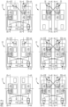
- FIG 2 shows a schematic flow diagram according to an update for the software version.
- the software version to be updated/previously installed for the first control function 24 is titled 24a and the updated software version is titled control function 24b.
- This is particularly the case for the first electronic computing device 18.
- the previously installed software version is titled 34a and the updated software version is titled 34b.
- the previously installed control function 24a has the previously installed internal first data sensor 22a and an updated internal first data sensor 22b.
- the previously installed control function 34a has the internal second data sensor 32a; the updated second control function 34b has the updated internal second data sensor 32b.
- the active components are marked with a thick line, while the inactive components are marked with a thinner line.
- FIG 2 it is shown that a new additional external data sensor 60 is provided for the update and a new yet additional external data sensor 62 is provided for the update.
- the FIG 2 shows in particular six time steps for performing the update. These six time steps are labeled S1 to S6.
- FIG 2 a method for updating a software version for the control function for the control functions 24a, 24b, 34a, 34b for the circuit arrangement 16 for controlling the machine 12 by means of the circuit arrangement 16.
- a data packet for updating the software version is received by means of the receiving device 54 of the circuit arrangement 16.
- the data packet is stored in the first storage device 56 of the first electronic computing device 18 and the data packet is stored in the second storage device 58 in the second electronic computing device 28.
- the first electronic computing device 18 is expanded with the additional external data sensor 60 and the second electronic computing device 28 is expanded with the yet additional external data sensor 62.
- the software version for updating is released by means of the further external data sensor 60 and the yet additional data sensor 62.
- the software version is updated on the second electronic computing device 28 depending on the release of the yet further data sensor 62 and the software version is updated on the first electronic computing device 18 depending on the release of the further data sensor 60.
- FIG 2 that in a first step S1 the previously installed first control function 24a takes over the control of the machine 12.
- the previously installed internal first data sensor 22a and the previously installed external first data sensor 40 take over the control and monitoring of the machine 12.
- the data packet is received.
- a preliminary test can be carried out in the second step S2 by the further external data sensor 60 and the yet further external data sensor 62.
- the updated second control function 34b is installed or updated in parallel to the previously installed second control function 34a.
- the updated second control function 34b is checked using the new external data sensors 60, 62. It is also provided that the previously installed first control function 24a takes over the control of the machine 12.
- the updated first control function 24b is installed.
- the control continues to take place via the previously installed first control function 24a.
- both the previously installed first control function 24a, the previously installed second control function 34a, the updated first control function 24b and the updated second control function 34b are present in the circuit arrangement 16.
- control functions 24a, 24b, 34a, 34b are also present in the electronic computing devices 18, 28.
- the control of the machine 12 is carried out via the updated first control function 24b.
- the new internal first data sensors 22b and the new external first data sensor 62 are used for monitoring.
- step S6 it is again shown that it can be provided that after updating the software version, the previously installed software version is deleted from the first electronic computing device 18 and/or the second electronic computing device 28.
- an active link to the machine 12 is established via the previously installed first control function 24a, while all other connections to the machine 12 are inactive.
- Two active emergency connections 26, 36 are in turn executed by the internal first data sensor 22a.
- the previously installed first control function 24a and the external first data sensor 40 are provided on physically different electronic computer devices 18, 28 in order to increase independence, and these in turn exchange corresponding monitoring data via connections 46.
- the circuit arrangement 16 continuously monitors the internal and external data sensors 22, 32, 38, 40, 60, 62.
- application-independent properties for a secure, seamless update of the control system functions are checked.
- application-independent properties of the control function 24, 34 such as the continuity of the function input value and function output value, are monitored.
- a smooth change from the software function to be updated is carried out as in FIG 2
- the method begins in the first step S1, whereby the previously installed first control function 24a and the previously installed second control function 34a are present.
- the configuration in the start-up phase is in particular, as shown in the FIG 1
- corresponding resources, in particular slots, for the next, redundant control function version with corresponding associated other external data sensors 60, 62 are blocked and are not used.
- the data packets are entered accordingly via the new external data sensors 60, 62 and released.
- a self-test can now be carried out and, if successful, the circuit arrangement 16 is informed that an update can be carried out.
- the updated software function is made available and released on the second electronic computing device 28 in what is known as hot standby.
- the updated second control function 34b begins by carrying out the preliminary activation tests, in particular using the updated internal data sensors 32b, whereby the associated actuator line is deactivated. If successful, the fourth step S4 is continued.
- the second electronic computing device 28 is provided and released for the updated version.
- the first electronic computing device 18 is then released to carry out the corresponding update.
- the previously installed first control function 24a is merged with the current first control function 24b.
- the previously installed first control function 24a and the updated second control function 34b run in parallel and carry out identical pre-activation tests when the actuator lines are blocked accordingly.
- the pre-switch-off tests are carried out using the circuit arrangement 16 for regression and thus a comparison mechanism is carried out. If the comparison results are the same, the tests before activation were successful.
- the software update on the first electronic computing device 18 can thus be carried out. If the comparison results are not the same, a problem has occurred on one of the electronic computing devices 18, 28.
- the control function 24, 34 cannot be updated. The Execution will therefore continue on the previously installed first control function 24a and an upgrade error will be triggered.
- the updated first control function 24b is activated as the primary control instance.
- the corresponding other control functions transfer the right to control the system environment, in particular the machine 12.
- the redundant control function instances go through the same phases in the same order at the same rhythm as the deactivated actuator lines.
- the circuit arrangement 16 switches from the previously installed software version to the updated software version, triggered by the internal data sensors 22a, 22b, 32a, 32b, which together with the control functions they accommodate switch from the previously installed control function 24a to the primary updated control function 24b.
- step S6 it is shown that the corresponding resources are released from the previously installed control function 24a, 34a immediately before another control function of a next version is to replace the updated control function 24b, 34b. Until then, it can also be provided that the previously installed control function 24a, 34b remains on standby and acts as a fallback if this is appropriate and safe for the control system and the controlled machine 12.
- the circuit arrangement 16 does not run with distributed, criss-crossed data sensors 22, 32, 38, 40 on the electronic computing devices 18, 28, but on an independent dashboard node where a system operator initiates and monitors the updating of the control function 24, 34, or on a third, dedicated computing node, e.g. a dedicated microcontroller or another industrial PC.
- a downgrade from, for example, the updated software version to the previously installed software function follows the same principle as the update itself.
- An event can initiate the downgrade. This event can be, for example, a button press by an authorized system operator via a dashboard node or a drop in performance below a reasonable threshold due to a change in the control functions 24, 34, which suggests downgrades, if not even an upgrade to another version.
- the circuit arrangement 16 detects the drop in performance through, for example, a health test and in turn initiates the downgrade. The downgrade is monitored accordingly. The downgrade also begins with the pre-activation tests on the second electronic computing device 28. After the upgrade, the corresponding control instances carry out the downgrade.
Landscapes
- Engineering & Computer Science (AREA)
- Theoretical Computer Science (AREA)
- Quality & Reliability (AREA)
- Physics & Mathematics (AREA)
- General Engineering & Computer Science (AREA)
- General Physics & Mathematics (AREA)
- Safety Devices In Control Systems (AREA)
Priority Applications (1)
| Application Number | Priority Date | Filing Date | Title |
|---|---|---|---|
| EP23191113.2A EP4506811A1 (fr) | 2023-08-11 | 2023-08-11 | Procédé de mise à jour d'une version logicielle pour une fonction de commande d'un agencement de circuit pour commander une machine au moyen de l'agencement de circuit, produit de programme informatique et agencements de circuit |
Applications Claiming Priority (1)
| Application Number | Priority Date | Filing Date | Title |
|---|---|---|---|
| EP23191113.2A EP4506811A1 (fr) | 2023-08-11 | 2023-08-11 | Procédé de mise à jour d'une version logicielle pour une fonction de commande d'un agencement de circuit pour commander une machine au moyen de l'agencement de circuit, produit de programme informatique et agencements de circuit |
Publications (1)
| Publication Number | Publication Date |
|---|---|
| EP4506811A1 true EP4506811A1 (fr) | 2025-02-12 |
Family
ID=87571315
Family Applications (1)
| Application Number | Title | Priority Date | Filing Date |
|---|---|---|---|
| EP23191113.2A Pending EP4506811A1 (fr) | 2023-08-11 | 2023-08-11 | Procédé de mise à jour d'une version logicielle pour une fonction de commande d'un agencement de circuit pour commander une machine au moyen de l'agencement de circuit, produit de programme informatique et agencements de circuit |
Country Status (1)
| Country | Link |
|---|---|
| EP (1) | EP4506811A1 (fr) |
Citations (2)
| Publication number | Priority date | Publication date | Assignee | Title |
|---|---|---|---|---|
| US20090076628A1 (en) * | 2007-09-18 | 2009-03-19 | David Mark Smith | Methods and apparatus to upgrade and provide control redundancy in process plants |
| US20200278856A1 (en) * | 2019-03-01 | 2020-09-03 | Abb Schweiz Ag | Online Firmware Upgrade Of A Node In A Process Control System |
-
2023
- 2023-08-11 EP EP23191113.2A patent/EP4506811A1/fr active Pending
Patent Citations (2)
| Publication number | Priority date | Publication date | Assignee | Title |
|---|---|---|---|---|
| US20090076628A1 (en) * | 2007-09-18 | 2009-03-19 | David Mark Smith | Methods and apparatus to upgrade and provide control redundancy in process plants |
| US20200278856A1 (en) * | 2019-03-01 | 2020-09-03 | Abb Schweiz Ag | Online Firmware Upgrade Of A Node In A Process Control System |
Similar Documents
| Publication | Publication Date | Title |
|---|---|---|
| EP2550599B1 (fr) | Système d'ordinateur de commande, procédé de commande d'un système d'ordinateur de commande, et utilisation d'un système d'ordinateur de commande | |
| WO2017137222A1 (fr) | Architecture informatique et fonctionnelle permettant d'augmenter la fiabilité d'une direction assistée | |
| EP2550598A1 (fr) | Commande à deux processeurs redondante et procédé de commande | |
| EP4359933A1 (fr) | Dispositif de commande et système d'assistance pour un véhicule | |
| WO2002074596A1 (fr) | Procede pour amorcer le composant d'un systeme reparti de securite | |
| EP1358554A1 (fr) | Mise en marche automatique d'un systeme a configuration en grappe apres une erreur reparable | |
| EP1854007A2 (fr) | Procede, systeme d'exploitation et dispositif de calcul pour executer un programme informatique | |
| DE102007056218A1 (de) | Verfahren zur Behandlung von transienten Fehlern in Echtzeitsystemen, insbesondere in Steuergeräten von Kraftfahrzeugen | |
| EP1810139B1 (fr) | Procédé, système d'exploitation et ordinateur pour l'exécution d'un programme informatique | |
| EP4506811A1 (fr) | Procédé de mise à jour d'une version logicielle pour une fonction de commande d'un agencement de circuit pour commander une machine au moyen de l'agencement de circuit, produit de programme informatique et agencements de circuit | |
| DE102017100119A1 (de) | Steuersystem für ein Kraftfahrzeug mit Hardware-Ausfallsicherung | |
| EP4502740A1 (fr) | Circuit pour une commande d'une machine, système de machine, procédé de génération d'un signal de commande pour un système de machine, produit-programme informatique et support d'enregistrement lisible par ordinateur | |
| EP2013731B1 (fr) | Agencement de circuit et procédé permettant de faire fonctionner un agencement de circuit | |
| EP1807760B1 (fr) | Systeme de traitement de donnees a frequence d'horloge variable | |
| EP4502739A1 (fr) | Procédé de contrôle d'une fonctionnalité d'un circuit de commande d'une machine au moyen du circuit, produit programme informatique, support de stockage lisible par ordinateur et circuit | |
| DE10329196A1 (de) | Verfahren zum Reset von elektronischen Fahrzeug-Steuergeräten | |
| EP1812853B1 (fr) | Procede, système d'exploitation et ordinateur pour l'execution d'un programme informatique | |
| EP4502738A1 (fr) | Circuit pour la commande d'une machine, système de machine, ainsi que procédé de production d'un signal de commande | |
| DE102013216558B4 (de) | Verfahren zur Diagnose eines steuerbaren Schaltelements eines Motorsteuergeräts | |
| DE102005061394A1 (de) | Fehlertolerantes Prozessorsystem | |
| DE102022212516A1 (de) | Steuervorrichtung und Verfahren für ein Bremssystem | |
| DE102017212560A1 (de) | Verfahren zum ausfallsicheren Durchführen einer sicherheitsgerichteten Funktion | |
| DE102022206080A1 (de) | Verfahren zum Betreiben einer Rechenanordnung | |
| EP4705874A1 (fr) | Procédé de mise à jour d'un composant logiciel sur un microcontrôleur, système de mise à jour et véhicule | |
| CH625066A5 (en) | Circuit arrangement for preventing sequence errors in a data processing system. |
Legal Events
| Date | Code | Title | Description |
|---|---|---|---|
| PUAI | Public reference made under article 153(3) epc to a published international application that has entered the european phase |
Free format text: ORIGINAL CODE: 0009012 |
|
| STAA | Information on the status of an ep patent application or granted ep patent |
Free format text: STATUS: THE APPLICATION HAS BEEN PUBLISHED |
|
| AK | Designated contracting states |
Kind code of ref document: A1 Designated state(s): AL AT BE BG CH CY CZ DE DK EE ES FI FR GB GR HR HU IE IS IT LI LT LU LV MC ME MK MT NL NO PL PT RO RS SE SI SK SM TR |
|
| STAA | Information on the status of an ep patent application or granted ep patent |
Free format text: STATUS: REQUEST FOR EXAMINATION WAS MADE |
|
| 17P | Request for examination filed |
Effective date: 20250718 |