EP4506918A1 - Détection de débit pour un système de détection de fumée par aspiration - Google Patents
Détection de débit pour un système de détection de fumée par aspiration Download PDFInfo
- Publication number
- EP4506918A1 EP4506918A1 EP24188569.8A EP24188569A EP4506918A1 EP 4506918 A1 EP4506918 A1 EP 4506918A1 EP 24188569 A EP24188569 A EP 24188569A EP 4506918 A1 EP4506918 A1 EP 4506918A1
- Authority
- EP
- European Patent Office
- Prior art keywords
- flow rate
- flow
- frequency
- gas
- receive coil
- Prior art date
- Legal status (The legal status is an assumption and is not a legal conclusion. Google has not performed a legal analysis and makes no representation as to the accuracy of the status listed.)
- Granted
Links
Images



Classifications
-
- G—PHYSICS
- G08—SIGNALLING
- G08B—SIGNALLING SYSTEMS, e.g. PERSONAL CALLING SYSTEMS; ORDER TELEGRAPHS; ALARM SYSTEMS
- G08B17/00—Fire alarms; Alarms responsive to explosion
- G08B17/10—Actuation by presence of smoke or gases, e.g. automatic alarm devices for analysing flowing fluid materials by the use of optical means
- G08B17/11—Actuation by presence of smoke or gases, e.g. automatic alarm devices for analysing flowing fluid materials by the use of optical means using an ionisation chamber for detecting smoke or gas
- G08B17/113—Constructional details
-
- G—PHYSICS
- G01—MEASURING; TESTING
- G01F—MEASURING VOLUME, VOLUME FLOW, MASS FLOW OR LIQUID LEVEL; METERING BY VOLUME
- G01F1/00—Measuring the volume flow or mass flow of fluid or fluent solid material wherein the fluid passes through a meter in a continuous flow
- G01F1/56—Measuring the volume flow or mass flow of fluid or fluent solid material wherein the fluid passes through a meter in a continuous flow by using electric or magnetic effects
- G01F1/58—Measuring the volume flow or mass flow of fluid or fluent solid material wherein the fluid passes through a meter in a continuous flow by using electric or magnetic effects by electromagnetic flowmeters
- G01F1/586—Measuring the volume flow or mass flow of fluid or fluent solid material wherein the fluid passes through a meter in a continuous flow by using electric or magnetic effects by electromagnetic flowmeters constructions of coils, magnetic circuits, accessories therefor
-
- G—PHYSICS
- G01—MEASURING; TESTING
- G01P—MEASURING LINEAR OR ANGULAR SPEED, ACCELERATION, DECELERATION, OR SHOCK; INDICATING PRESENCE, ABSENCE, OR DIRECTION, OF MOVEMENT
- G01P5/00—Measuring speed of fluids, e.g. of air stream; Measuring speed of bodies relative to fluids, e.g. of ship, of aircraft
-
- G—PHYSICS
- G01—MEASURING; TESTING
- G01F—MEASURING VOLUME, VOLUME FLOW, MASS FLOW OR LIQUID LEVEL; METERING BY VOLUME
- G01F1/00—Measuring the volume flow or mass flow of fluid or fluent solid material wherein the fluid passes through a meter in a continuous flow
- G01F1/05—Measuring the volume flow or mass flow of fluid or fluent solid material wherein the fluid passes through a meter in a continuous flow by using mechanical effects
- G01F1/20—Measuring the volume flow or mass flow of fluid or fluent solid material wherein the fluid passes through a meter in a continuous flow by using mechanical effects by detection of dynamic effects of the flow
- G01F1/32—Measuring the volume flow or mass flow of fluid or fluent solid material wherein the fluid passes through a meter in a continuous flow by using mechanical effects by detection of dynamic effects of the flow using swirl flowmeters
- G01F1/3209—Measuring the volume flow or mass flow of fluid or fluent solid material wherein the fluid passes through a meter in a continuous flow by using mechanical effects by detection of dynamic effects of the flow using swirl flowmeters using Karman vortices
-
- G—PHYSICS
- G01—MEASURING; TESTING
- G01F—MEASURING VOLUME, VOLUME FLOW, MASS FLOW OR LIQUID LEVEL; METERING BY VOLUME
- G01F1/00—Measuring the volume flow or mass flow of fluid or fluent solid material wherein the fluid passes through a meter in a continuous flow
- G01F1/05—Measuring the volume flow or mass flow of fluid or fluent solid material wherein the fluid passes through a meter in a continuous flow by using mechanical effects
- G01F1/20—Measuring the volume flow or mass flow of fluid or fluent solid material wherein the fluid passes through a meter in a continuous flow by using mechanical effects by detection of dynamic effects of the flow
- G01F1/32—Measuring the volume flow or mass flow of fluid or fluent solid material wherein the fluid passes through a meter in a continuous flow by using mechanical effects by detection of dynamic effects of the flow using swirl flowmeters
- G01F1/325—Means for detecting quantities used as proxy variables for swirl
- G01F1/3259—Means for detecting quantities used as proxy variables for swirl for detecting fluid pressure oscillations
- G01F1/3266—Means for detecting quantities used as proxy variables for swirl for detecting fluid pressure oscillations by sensing mechanical vibrations
-
- G—PHYSICS
- G01—MEASURING; TESTING
- G01N—INVESTIGATING OR ANALYSING MATERIALS BY DETERMINING THEIR CHEMICAL OR PHYSICAL PROPERTIES
- G01N1/00—Sampling; Preparing specimens for investigation
- G01N1/02—Devices for withdrawing samples
- G01N1/10—Devices for withdrawing samples in the liquid or fluent state
- G01N1/14—Suction devices, e.g. pumps; Ejector devices
-
- G—PHYSICS
- G01—MEASURING; TESTING
- G01N—INVESTIGATING OR ANALYSING MATERIALS BY DETERMINING THEIR CHEMICAL OR PHYSICAL PROPERTIES
- G01N15/00—Investigating characteristics of particles; Investigating permeability, pore-volume or surface-area of porous materials
-
- G—PHYSICS
- G01—MEASURING; TESTING
- G01N—INVESTIGATING OR ANALYSING MATERIALS BY DETERMINING THEIR CHEMICAL OR PHYSICAL PROPERTIES
- G01N33/00—Investigating or analysing materials by specific methods not covered by groups G01N1/00 - G01N31/00
- G01N33/0004—Gaseous mixtures, e.g. polluted air
- G01N33/0009—General constructional details of gas analysers, e.g. portable test equipment
- G01N33/0027—General constructional details of gas analysers, e.g. portable test equipment concerning the detector
Definitions
- the present disclosure relates to methods, devices, and systems for flow rate detection for an aspirating smoke detection system.
- FIG. 1 An alarm system
- FIG. 1 An alarm system
- FIG. 1 An alarm system
- FIG. 1 An alarm system
- FIG. 1 An alarm system
- FIG. 1 An alarm system
- FIG. 1 An alarm system
- FIG. 1 An alarm system
- FIG. 1 An alarm system
- FIG. 1 An alarm system
- FIG. 1 An alarm system
- FIG. 1 An alarm system
- FIG. 1 An alarm system
- FIG. 1 An alarm system
- FIG. 1 An alarm system
- FIG. 1 An alarm system
- FIG. 1 An alarm system
- FIG. 1 An alarm system
- FIG. 1 An alarm system
- FIG. 1 An alarm system
- FIG. 1 An alarm system
- FIG. 1 An alarm system
- FIG. 1 An alarm system
- FIG. 1 An alarm system
- FIG. 1 An alarm system
- FIG. 1 An alarm system
- FIG. 1 An alarm system
- FIG. 1 An alarm system
- FIG. 1 An alarm system
- FIG. 1 An alarm system
- One device includes a flow rate sensor for an aspirating smoke detection system comprising a flow chamber to allow a gas to flow through the flow chamber and a receive coil located inside the flow chamber, where a processor is to execute instructions to receive a signal from the receive coil and determine a flow rate of gas through the flow chamber based on the signal.
- An aspirating smoke detector device can be utilized as part of an aspirating smoke detection system in a facility to detect a hazard event by detecting the presence of smoke.
- the aspirating smoke detector device can draw gas (e.g., air, via a blower) from the facility into a sensor through a network of pipes throughout the facility.
- the network of pipes can comprise a pipe sampling network.
- the sensor can sample the gas from the pipe sampling network in order to determine whether the gas sampled from the facility includes smoke particles.
- the aspirating smoke detector device can transmit a signal to a control panel in the facility to signal detection of smoke particles in the area of the facility the aspirating smoke detector is monitoring and sampling gas from.
- the aspirating smoke detector device can utilize the network of pipes throughout the facility to transport sampled gas to the aspirating smoke detector device.
- the pipe sampling network can transport gas from an area of the facility to the aspirating smoke detector device for testing.
- the gas is to flow through the network of sampling pipes to the aspirating smoke detector device at a known flow rate. Determining the flow rate of the gas ensures the aspirating smoke detector device is operating correctly. Additionally, sensing and monitoring the flow rate of the gas through the network of sampling pipes may be a regulatory requirement in certain jurisdictions to ensure safe operation of a facility.
- a flow rate sensor can be utilized for flow rate detection for an aspirating smoke detection system.
- the flow rate sensor can be an easy to manufacture sensor that can be easily implemented in any new or existing aspirating smoke detection system. Such an approach can allow for a cheaper flow rate sensor that is easy to install, as compared with previous approaches.
- Figure 1 is an aspirating smoke detection system 100 having a flow rate sensor 104, in accordance with one or more embodiments of the present disclosure.
- system 100 can include a pipe sampling network 102, a flow rate sensor 104, an aspirating smoke detector device 106, and a blower 108.
- the system 100 can include a pipe sampling network 102.
- pipe sampling network refers to a group of pipes configured to take samples of gas at a sampling location and transport the gas from the sampling location to a detector.
- the pipe sampling network 102 can sample gas at various sampling locations (e.g., not illustrated in Figure 1 for clarity and so as not to obscure embodiments of the present disclosure) and transport the gas to the aspirating smoke detector device 106 for analysis.
- the pipe sampling network 102 can include various sampling ports located throughout the pipe sampling network 102.
- the term "port" refers to an aperture in a pipe. The sampling ports can allow for gas to flow from an area in the facility into the pipe sampling network 102.
- the pipe sampling network 102 is illustrated in Figure 1 as being a singular pipe, embodiments of the present disclosure are not so limited.
- the pipe sampling network 102 can include more than one pipe.
- more than one pipe may connect to the aspirating smoke detector device 106.
- the system 100 can include a blower 108.
- the term "blower” refers to a mechanical device for moving gas in a particular direction.
- the blower 108 can be utilized to cause a flow of gas through the pipe sampling network 102 and into the aspirating smoke detector device 106.
- the blower 108 can, in some instances, comprise a ducted housing having a fan that, when spinning, causes gas (e.g., such as air) to flow in a particular direction.
- the system 100 further includes the aspirating smoke detector device 106 that is connected to the pipe sampling network 102.
- the aspirating smoke detector device 106 can detect smoke particles within gas sampled from the sampling locations in the facility.
- a flow rate of gas through the pipe sampling network 102 and into the aspirating smoke detector device 106 can be determined by a flow rate sensor 104, as is further described herein.
- the system 100 includes a flow rate sensor 104.
- the term "flow rate sensor” refers to a device that measures the flow of a fluid.
- a fluid can be, for example, gas and/or liquid.
- the flow rate sensor 104 can measure a volume of gas which passes a location per unit of time.
- the flow rate sensor 104 can include a flow chamber connected to the pipe sampling network 102, a coil, and a controller.
- the flow chamber can be connected to the pipe sampling network 102 such that the flow of gas flows through the flow chamber.
- the controller can be configured to receive a signal from the coil, and determine a flow rate of gas through the flow chamber based on the signal.
- the coil is configured to physically oscillate in response to the flow of gas through the flow chamber.
- the controller is configured to determine a frequency of the signal, the frequency being associated with the physical oscillation of the coil, and determine a flow rate of the gas through the flow chamber based on the frequency, as is further described in connection with Figure 2 .
- the coil can be connected to a flexible base configured to deflect into the flow of gas in the flow chamber in response to a voltage being applied to the coil.
- the controller is configured to determine whether an amplitude associated with the voltage exceeds a threshold amplitude amount, and determine, in response to the amplitude exceeding the threshold amplitude amount, a flow rate of the gas through the flow chamber based on the voltage applied to the coil, as is further described in connection with Figures 3A and 3B .
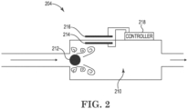
- FIG. 2 is a top view of an example of a flow rate sensor 204 having a receive coil 214 and a transmit coil 216, in accordance with one or more embodiments of the present disclosure.
- the flow rate sensor 204 can further include a flow chamber 210, a bluff body 212, and a controller 218.
- the flow rate sensor 204 can be connected to a pipe sampling network.
- the flow chamber 210 can be connected to the pipe sampling network such that gas is allowed to flow from the pipe sampling network and through the flow chamber 210 of the flow rate sensor 204.
- the gas can encounter bluff body 212.
- the bluff body 212 can be located inside the flow chamber 210 and can disrupt the flow of gas through the flow chamber 210.
- the term "bluff body” refers to an object which, as a result of its shape, causes flow separation of a flow of fluid over the body.
- the bluff body 212 causes the gas flow to separate, resulting in detachment of a boundary layer of the flow from a surface of the bluff body 212 into a wake.
- the bluff body 212 is to cause the gas flowing through the flow chamber 210 to be a turbulent flow in the flow chamber 210.
- the flow rate sensor 204 can further include a receive coil 214 located inside the flow chamber 210.
- the receive coil 214 can be an electrical conductor in the shape of a coil where, upon application of an electric current, the coil can generate a magnetic field.
- the receive coil 214 can be located on a printed circuit board (PCB).
- the PCB can be a polyimide PCB on which the receive coil 214 is located.
- the receive coil 214 can be located downstream of the bluff body 212 in the flow chamber 210. Accordingly, the receive coil 214 (e.g., the PCB) can physically oscillate in response to the flow of gas acting upon the receive coil 214. For example, the disrupted (e.g., turbulent) flow of the gas after interaction with the bluff body 212 as the gas flows through the flow chamber 210 can physically act upon (e.g., apply a force in varying magnitude to) the receive coil 214. As a result, the receive coil 214 can oscillate.
- the disrupted flow of the gas after interaction with the bluff body 212 as the gas flows through the flow chamber 210 can physically act upon (e.g., apply a force in varying magnitude to) the receive coil 214.
- the receive coil 214 can oscillate.
- the receive coil 214 can generate a signal.
- the signal can be, for example, an amplitude modulated signal.
- the flow rate sensor 204 can further include a transmit coil 216. As illustrated in Figure 2 , the transmit coil 216 can also be located downstream of the bluff body 212. The transmit coil 216 can be located outside of the flow chamber 210 and at a same position downstream of the bluff body 212 as the receive coil 214.
- the transmit coil 216 is illustrated in Figure 2 as being located outside of the flow chamber 210, embodiments of the present disclosure are not so limited.
- the transmit coil 216 can be located inside of the flow chamber 210, be integrated within the body of the flow chamber 210, etc.
- the transmit coil 216 can be an electromagnet located on a PCB.
- the transmit coil 216 can be a type of magnet in which a magnetic field is produced by the transmit coil 216 when an electric current is passed through a coil surrounding the magnet.
- the receive coil 214 and the transmit coil 216 can be electrically connected to the controller 218. Accordingly, the receive coil 214 and the transmit coil 216 can transmit signals to and/or receive signals from the controller 218.
- the controller 218 can cause an oscillating signal to be applied to the transmit coil 216.
- Such an oscillating signal can cause the receive coil 214 to generate a signal in response to the physical oscillation of the receive coil 214 (e.g., experienced by the receive coil 214 as a result of the disrupted flow of the gas through the flow chamber 210 caused by the bluff body 212).
- the signal generated by the receive coil 214 in response to the physical oscillation of the receive coil 214 can be transmitted to the controller 218. Accordingly, the controller 218 can determine a frequency of the signal generated by the receive coil 214. In order to determine the frequency, the controller 218 can demodulate the signal generated by the receive coil 214.
- the controller 218 can determine a flow rate of the gas through the flow chamber 210 based on the frequency of the signal.
- the controller 218 can include a memory (e.g., not illustrated in Figure 2 for clarity and so as not to obscure embodiments of the present disclosure).
- the memory can include a lookup table stored therein. Accordingly, the controller 218 can determine the flow rate by comparing the frequency of the signal to a plurality of frequencies included in the lookup table and determining, based on the frequency matching a particular frequency in the lookup table, the flow rate to be a particular flow rate from the lookup table that is associated with the particular frequency.
- the lookup table may include a frequency of 100 Hertz (Hz) with an associated flow rate of 10 Liters per minute (L/m) and a frequency of 150 Hz with an associated flow rate of 15 L/m.
- the controller 218 can compare the determined frequency (e.g., 400 Hz) to the plurality of frequencies included in the lookup table (e.g., 400 Hz, 500 Hz, etc.) and determine, based on the determined frequency (e.g., 400 Hz) matching a frequency of the plurality of frequencies in the lookup table (e.g., 400 Hz), the flow rate to be 10 L/m.
- the determined frequency may not match exactly those frequencies of the plurality of frequencies in the lookup table.
- the determined frequency may be 412 Hz.
- the controller 218 can determine a frequency of the plurality of frequencies (e.g., 400 Hz) in the lookup table that is the closest to the determined frequency (e.g., 412 Hz), and determine the flow rate to be 10 L/m.
- the closest frequency may not result in the accuracy desired and/or mandated in determining the flow rate.
- the controller 218 can interpolate between those frequencies of the plurality of frequencies in the lookup table to determine an exact flow rate.
- the determined frequency may be 412 Hz
- the controller 218 can interpolate, using the two closest frequencies of the plurality of frequencies (e.g., 400 Hz and 500 Hz) to the determined frequency, to determine the flow rate associated with the 412 Hz frequency to be approximately 10.6 L/m.
- Figure 3A is a top view of an example of a flow rate sensor 305 having a magnet 320 and a sensing coil 317 in a first position, in accordance with one or more embodiments of the present disclosure.
- the flow rate sensor 305 can further include a flow chamber 310, an inner surface 311 of the flow chamber 310, and a controller 318.
- the flow rate sensor 305 can be connected to a pipe sampling network.
- the flow chamber 310 can be connected to the pipe sampling network such that gas is allowed to flow from the pipe sampling network and through the flow chamber 310 of the flow rate sensor 305.
- the flow rate sensor 305 can include a magnet 320.
- the magnet 320 can be an object that produces a magnetic field.
- the flow rate sensor 305 can further include a sensing coil 317 having a flexible base 315.
- the sensing coil 317 having the flexible base 315 can be located inside the flow chamber 310.
- the sensing coil 317 can be an electrical conductor in the shape of a coil where, upon application of an electric current, the coil can generate a magnetic field.
- the flexible base 315 can be a flexible PCB, and the sensing coil 317 can be located on the flexible PCB.
- the flexible PCB can be a polyimide flat flex PCB.
- the sensing coil 317 having the flexible base 315 can be at the first position.
- the flexible base 315 can be located proximate to the inner surface 311 of the flow chamber 310.
- the sensing coil 317 and the flexible base 315 do not substantially interact with the flow of the gas through the flow chamber 310, as they are oriented in a direction substantially similar to the flow direction of the gas through the flow chamber 310. That is, the orientation of the sensing coil 317 and the flexible base 315 at the first position is substantially parallel to the flow direction of the gas through the flow chamber 310.
- the sensing coil 317 with the flexible base 315 are located inside the flow chamber 310, whereas the magnet 320 is located outside of the flow chamber 310.
- the magnet 320 can be located inside the flow chamber 310, be integrated within the body of the flow chamber 310, etc.
- the sensing coil 317 and the magnet 320 can be electrically connected to the controller 318. Accordingly, the sensing coil 317 and the magnet 320 can transmit signals to and/or receive signals from the controller 318.
- the controller 318 can cause a direct current (DC) voltage to be applied to the sensing coil 317.
- the sensing coil 317 can accordingly receive the DC voltage from the controller 318 for the purpose of controlling the displacement of the coil with respect to the magnet.
- Such a mechanism for measurement of the coil inductance can be indicative of proximity to the metallic component of the magnet.
- the signal from the controller 318 can be an oscillating AC voltage signal having a high impedance and high frequency.
- the AC voltage can be applied having an impedance of 100 ohms and a frequency of 10 MHz, among other examples.
- the magnet 320 can cause the sensing coil 317 having the flexible base 315 to deflect from the first position to a second position.
- the receive coil can more substantially interact with the flow of gas through the flow chamber 310, allowing for the determination for the flow rate of the gas through the flow chamber 310, as is further described in connection with Figure 3B .
- Figure 3B is a top view of an example of a flow rate sensor 305 having a magnet 320 and a sensing coil 317 in a second position, in accordance with one or more embodiments of the present disclosure.
- the flow rate sensor 305 can further include the flow chamber 310, the inner surface 311 of the flow chamber 310, and the controller 318.
- the magnet 320 can cause the sensing coil 317 having the flexible base 315 to deflect from the first position (e.g., as previously illustrated in Figure 3A ) to a second position (e.g., as illustrated in Figure 3B ).
- the sensing coil 317 having the flexible base 315 When the sensing coil 317 having the flexible base 315 is at the second position, the sensing coil 317 having the flexible base 315 protrudes away from the inner surface 311 of the flow chamber 310 and into the flow of gas through the flow chamber 310.
- the application of the DC voltage to the sensing coil 317 causes the sensing coil 317 to be repelled away from the magnet 320 as a result of magnetic opposition with the magnet 320.
- application of the DC voltage to the sensing coil 317 can cause the sensing coil 317 to protrude a particular distance (e.g., away from the inner surface 311) into the flow of gas.
- the gas flowing through the flow chamber 310 can exert a force on the sensing coil 317 when the receive coil protrudes into the flow of gas in the flow chamber 310.
- the orientation of the sensing coil 317 and the flexible base 315 at the second position is no longer substantially parallel to the flow direction of the gas through the flow chamber 310 like it was in the first position; rather, the sensing coil 317 and the flexible base 315 protrude into the flow direction of the gas and the gas impinges upon the sensing coil 317 and the flexible base 315, providing a force that tries to push the sensing coil 317 and the flexible base 315 back to the first position (e.g., but which is counteracted by the magnetic opposition from the magnet 320.
- the applied DC voltage to the sensing coil 317 can have a relationship with an amount of force required to move the sensing coil 317 with the flexible base 315 to the second position, and as such, a flow rate of the gas through the flow chamber 310 can be inferred, as is further described herein.
- the controller 318 can measure an amplitude of the applied AC voltage at the sensing coil 317.
- a predetermined amplitude threshold may be known such that when the measured amplitude at the sensing coil 317 meets and/or exceeds the threshold, the controller 318 determines the sensing coil 317 having the flexible base 315 is at the second position.
- the controller 318 can determine whether the measured amplitude of the AC voltage associated with the DC voltage while the flexible base 315 is at the second position exceeds the threshold amplitude amount. Accordingly, the controller 318 can determine, in response to the amplitude exceeding the threshold amplitude amount, the flow rate of the gas through the flow chamber 310 based on the DC voltage, as is further described herein.
- the controller 318 can determine a flow rate of the gas through the flow chamber 310 based on the applied DC voltage to the sensing coil 317.
- the controller 318 can include a memory (e.g., not illustrated in Figure 3B for clarity and so as not to obscure embodiments of the present disclosure).
- the memory can include a lookup table stored therein. Accordingly, the controller 318 can determine the flow rate by comparing the applied DC voltage to a plurality of DC voltages included in the lookup table and determining, based on the DC voltage matching a particular DC voltage in the lookup table, the flow rate to be a particular flow rate from the lookup table that is associated with the particular DC voltage.
- the lookup table may include a DC voltage of 2 Volts (V) with an associated flow rate of 10 Liters per minute (L/m) and a voltage of 3 V with an associated flow rate of 15 L/m.
- the controller 318 can compare the applied DC voltage (e.g., 2 V) to the plurality of DC voltages included in the lookup table (e.g., 2 V, 3 V, etc.) and determine, based on the applied DC voltage (e.g., 2 V) matching a DC voltage of the plurality of DC voltages in the lookup table (e.g., 2 V), the flow rate to be 10 L/m.
- the applied DC voltage may not match exactly those DC voltages of the plurality of DC voltages in the lookup table.
- the applied DC voltage may be 2.2 V.
- the controller 318 can determine a DC voltage of the plurality of DC voltages (e.g., 2 V) in the lookup table that is the closest to the applied DC voltage (e.g., 2.2 V), and determine the flow rate to be 10 L/m.
- the closest frequency may not result in the accuracy desired and/or mandated in determining the flow rate.
- the controller 318 can interpolate between those DC voltages of the plurality of DC voltages in the lookup table to determine an exact flow rate.
- the applied DC voltage may be 2.4 V
- the controller 318 can interpolate, using the two closest DC voltages of the plurality of frequencies (e.g., 2 V and 3 V) to the applied DC voltage, to determine the flow rate associated with the applied DC voltage of 2.4 V to be approximately 12 L/m.
- the resulting amplitude of the DC voltage applied to the sensing coil 317 can represent an amount of force required to deflect and hold the sensing coil 317 having the flexible base 315 in the gas flow, and as such, the flow rate can be inferred from the applied DC voltage to the sensing coil 317. Accordingly, if the flow rate of the gas through the flow chamber 310 increases, additional force would be required to keep the sensing coil 317 with the flexible base 315 at the second position (e.g., in the gas flow), and as such, the applied DC voltage to the sensing coil 317 would have to be increased.
- the controller 318 can adjust the DC voltage (e.g., increase the DC voltage) applied to the sensing coil 317 to a revised DC voltage, where at the revised DC voltage, the measured amplitude exceeds the threshold amplitude amount. Utilizing the lookup tables, the controller 318 can then determine the flow rate utilizing the revised DC voltage. Accordingly, such an approach can be utilized to determine the flow rate of the gas through the flow chamber 310, even if the flow rate changes.
- Flow rate detection for an aspirating smoke detection system can allow for a flow rate sensor to be utilized for flow rate detection.
- the flow rate sensor can be easy to manufacture and implement in new and/or existing aspirating smoke detection systems. Such an approach can allow for a cheaper and easier to install flow rate sensor, as compared with previous approaches.
- FIG 4 is a controller 402 for flow rate detection for an aspirating smoke detection system, in accordance with one or more embodiments of the present disclosure.
- the controller 402 can include a memory 442, and a processor 440 for flow rate detection for an aspirating smoke detection system in accordance with the present disclosure.
- the memory 442 can be any type of storage medium that can be accessed by the processor 440 to perform various examples of the present disclosure.
- the memory 442 can be a non-transitory computer readable medium having computer readable instructions (e.g., computer program instructions) stored thereon that are executable by the processor 440 for flow rate detection for an aspirating smoke detection system in accordance with the present disclosure.
- the computer readable instructions can be executable by the processor 440 to redundantly perform flow rate detection for an aspirating smoke detection system.
- the memory 442 can be volatile or nonvolatile memory.
- the memory 442 can also be removable (e.g., portable) memory, or non-removable (e.g., internal) memory.
- the memory 442 can be random access memory (RAM) (e.g., dynamic random access memory (DRAM) and/or phase change random access memory (PCRAM)), read-only memory (ROM) (e.g., electrically erasable programmable read-only memory (EEPROM) and/or compact-disc read-only memory (CD-ROM)), flash memory, a laser disc, a digital versatile disc (DVD) or other optical storage, and/or a magnetic medium such as magnetic cassettes, tapes, or disks, among other types of memory.
- RAM random access memory
- DRAM dynamic random access memory
- PCRAM phase change random access memory
- ROM read-only memory
- EEPROM electrically erasable programmable read-only memory
- CD-ROM compact-disc read-only memory
- flash memory a laser disc
- memory 442 is illustrated as being located within controller 402, embodiments of the present disclosure are not so limited.
- memory 442 can also be located internal to another computing resource (e.g., enabling computer readable instructions to be downloaded over the Internet or another wired or wireless connection).
Landscapes
- Physics & Mathematics (AREA)
- General Physics & Mathematics (AREA)
- Chemical & Material Sciences (AREA)
- Life Sciences & Earth Sciences (AREA)
- Engineering & Computer Science (AREA)
- Health & Medical Sciences (AREA)
- Analytical Chemistry (AREA)
- Pathology (AREA)
- General Health & Medical Sciences (AREA)
- Immunology (AREA)
- Biochemistry (AREA)
- Fluid Mechanics (AREA)
- Combustion & Propulsion (AREA)
- Food Science & Technology (AREA)
- Medicinal Chemistry (AREA)
- Power Engineering (AREA)
- Electromagnetism (AREA)
- Aviation & Aerospace Engineering (AREA)
- Dispersion Chemistry (AREA)
- Hydrology & Water Resources (AREA)
- Business, Economics & Management (AREA)
- Emergency Management (AREA)
- Measuring Volume Flow (AREA)
Applications Claiming Priority (1)
| Application Number | Priority Date | Filing Date | Title |
|---|---|---|---|
| US18/230,817 US20250052600A1 (en) | 2023-08-07 | 2023-08-07 | Flow rate detection for an aspirating smoke detection system |
Publications (2)
| Publication Number | Publication Date |
|---|---|
| EP4506918A1 true EP4506918A1 (fr) | 2025-02-12 |
| EP4506918B1 EP4506918B1 (fr) | 2026-03-18 |
Family
ID=91950475
Family Applications (1)
| Application Number | Title | Priority Date | Filing Date |
|---|---|---|---|
| EP24188569.8A Active EP4506918B1 (fr) | 2023-08-07 | 2024-07-15 | Détection de débit pour un système de détection de fumée par aspiration |
Country Status (3)
| Country | Link |
|---|---|
| US (1) | US20250052600A1 (fr) |
| EP (1) | EP4506918B1 (fr) |
| CN (1) | CN119438623A (fr) |
Citations (4)
| Publication number | Priority date | Publication date | Assignee | Title |
|---|---|---|---|---|
| US5443552A (en) * | 1993-06-21 | 1995-08-22 | Kabushiki Kaisha Toshiba | Electromagnetic flowmeter and method for electromagnetically measuring flow rate |
| US6351999B1 (en) * | 1998-06-25 | 2002-03-05 | Endress + Hauser Flowtec Ag | Vortex flow sensor |
| US20150128722A1 (en) * | 2003-05-14 | 2015-05-14 | Xtralis Technologies Ltd. | Sensing apparatus and method |
| WO2018024984A1 (fr) * | 2016-08-02 | 2018-02-08 | Finsecur | Détecteur de fumée, de gaz ou de particules, système et procédé de détection de fumée, de gaz ou de particules |
Family Cites Families (4)
| Publication number | Priority date | Publication date | Assignee | Title |
|---|---|---|---|---|
| US4123940A (en) * | 1977-09-23 | 1978-11-07 | Fischer & Porter Company | Transmission system for vortex-shedding flowmeter |
| US6626048B1 (en) * | 1998-09-29 | 2003-09-30 | Sensus Technologies Inc. | Magnetic flow meter |
| IT201800002751A1 (it) * | 2018-02-16 | 2019-08-16 | Eltek Spa | Dispositivo di rilevazione e/o controllo per apparecchi o sistemi a conduzione di liquido |
| US20200217698A1 (en) * | 2019-01-09 | 2020-07-09 | Georg Fischer Signet Llc | Magnetic flowmeter with media conductivity measurement |
-
2023
- 2023-08-07 US US18/230,817 patent/US20250052600A1/en active Pending
-
2024
- 2024-07-02 CN CN202410879466.7A patent/CN119438623A/zh active Pending
- 2024-07-15 EP EP24188569.8A patent/EP4506918B1/fr active Active
Patent Citations (4)
| Publication number | Priority date | Publication date | Assignee | Title |
|---|---|---|---|---|
| US5443552A (en) * | 1993-06-21 | 1995-08-22 | Kabushiki Kaisha Toshiba | Electromagnetic flowmeter and method for electromagnetically measuring flow rate |
| US6351999B1 (en) * | 1998-06-25 | 2002-03-05 | Endress + Hauser Flowtec Ag | Vortex flow sensor |
| US20150128722A1 (en) * | 2003-05-14 | 2015-05-14 | Xtralis Technologies Ltd. | Sensing apparatus and method |
| WO2018024984A1 (fr) * | 2016-08-02 | 2018-02-08 | Finsecur | Détecteur de fumée, de gaz ou de particules, système et procédé de détection de fumée, de gaz ou de particules |
Also Published As
| Publication number | Publication date |
|---|---|
| US20250052600A1 (en) | 2025-02-13 |
| EP4506918B1 (fr) | 2026-03-18 |
| CN119438623A (zh) | 2025-02-14 |
Similar Documents
| Publication | Publication Date | Title |
|---|---|---|
| JP6114267B2 (ja) | 可変周波数型電磁流量計 | |
| US12055521B2 (en) | Detection of blockage in a porous member | |
| US7505861B2 (en) | Method for monitoring the installation of a measurement device | |
| US2648058A (en) | Liquid level indicating device | |
| CN101424652A (zh) | 用于测量测量介质中的杂质的方法和设备 | |
| US9784603B2 (en) | Electromagnetic flowmeter empty pipe detection system | |
| US11761875B2 (en) | Adjusting for air flow temperature changes in an aspirating smoke detector | |
| US20170350865A1 (en) | Flow Measuring Device | |
| US7508222B2 (en) | Electromagnetic flow meter | |
| EP4506918A1 (fr) | Détection de débit pour un système de détection de fumée par aspiration | |
| US7692539B2 (en) | Automated mechanical integrity verification | |
| US2441677A (en) | Detecting and indicating system for explosive gases | |
| CN205719182U (zh) | 检测装置 | |
| CN215178056U (zh) | 一种高精度电磁流量计标定系统 | |
| JPS63139202A (ja) | 電磁誘導形肉厚測定方法および測定装置 | |
| Perovic et al. | Electromagnetic flowmeters as a source of diagnostic information | |
| JP6864843B2 (ja) | 電磁誘導式電気伝導率計 | |
| CN212275076U (zh) | 一种自动调节环境温度的测温舱 | |
| EP3732447B1 (fr) | Débitmètre électromagnétique de type serre-tube | |
| CN117517404A (zh) | 用于检测气阱失效的熔丝 | |
| JPH04295721A (ja) | セラミック電磁流量計 | |
| Long | The effect of humidity variation on the operation of an electronic proximity switch | |
| JPS61173150A (ja) | フロ−スル形イオンメ−タ | |
| JPS6195213A (ja) | 電磁流量計 | |
| Velt et al. | New electromagnetic flowmeters for liquid metal |
Legal Events
| Date | Code | Title | Description |
|---|---|---|---|
| PUAI | Public reference made under article 153(3) epc to a published international application that has entered the european phase |
Free format text: ORIGINAL CODE: 0009012 |
|
| STAA | Information on the status of an ep patent application or granted ep patent |
Free format text: STATUS: REQUEST FOR EXAMINATION WAS MADE |
|
| 17P | Request for examination filed |
Effective date: 20240715 |
|
| AK | Designated contracting states |
Kind code of ref document: A1 Designated state(s): AL AT BE BG CH CY CZ DE DK EE ES FI FR GB GR HR HU IE IS IT LI LT LU LV MC ME MK MT NL NO PL PT RO RS SE SI SK SM TR |
|
| GRAP | Despatch of communication of intention to grant a patent |
Free format text: ORIGINAL CODE: EPIDOSNIGR1 |
|
| STAA | Information on the status of an ep patent application or granted ep patent |
Free format text: STATUS: GRANT OF PATENT IS INTENDED |
|
| INTG | Intention to grant announced |
Effective date: 20251028 |
|
| GRAS | Grant fee paid |
Free format text: ORIGINAL CODE: EPIDOSNIGR3 |
|
| GRAA | (expected) grant |
Free format text: ORIGINAL CODE: 0009210 |
|
| STAA | Information on the status of an ep patent application or granted ep patent |
Free format text: STATUS: THE PATENT HAS BEEN GRANTED |
|
| AK | Designated contracting states |
Kind code of ref document: B1 Designated state(s): AL AT BE BG CH CY CZ DE DK EE ES FI FR GB GR HR HU IE IS IT LI LT LU LV MC ME MK MT NL NO PL PT RO RS SE SI SK SM TR |
|
| REG | Reference to a national code |
Ref country code: CH Ref legal event code: F10 Free format text: ST27 STATUS EVENT CODE: U-0-0-F10-F00 (AS PROVIDED BY THE NATIONAL OFFICE) Effective date: 20260318 Ref country code: GB Ref legal event code: FG4D |
|
| REG | Reference to a national code |
Ref country code: IE Ref legal event code: FG4D |
|
| REG | Reference to a national code |
Ref country code: DE Ref legal event code: R096 Ref document number: 602024003257 Country of ref document: DE |