EP4507014A1 - Negativelektrodenmaterial, negativelektrodenplatte und herstellungsverfahren dafür sowie lithium-ionen-batterie und herstellungsverfahren dafür - Google Patents
Negativelektrodenmaterial, negativelektrodenplatte und herstellungsverfahren dafür sowie lithium-ionen-batterie und herstellungsverfahren dafür Download PDFInfo
- Publication number
- EP4507014A1 EP4507014A1 EP22939436.6A EP22939436A EP4507014A1 EP 4507014 A1 EP4507014 A1 EP 4507014A1 EP 22939436 A EP22939436 A EP 22939436A EP 4507014 A1 EP4507014 A1 EP 4507014A1
- Authority
- EP
- European Patent Office
- Prior art keywords
- silicon
- carbon
- anode material
- anode
- range
- Prior art date
- Legal status (The legal status is an assumption and is not a legal conclusion. Google has not performed a legal analysis and makes no representation as to the accuracy of the status listed.)
- Pending
Links
Images

Classifications
-
- H—ELECTRICITY
- H01—ELECTRIC ELEMENTS
- H01M—PROCESSES OR MEANS, e.g. BATTERIES, FOR THE DIRECT CONVERSION OF CHEMICAL ENERGY INTO ELECTRICAL ENERGY
- H01M4/00—Electrodes
- H01M4/02—Electrodes composed of, or comprising, active material
- H01M4/36—Selection of substances as active materials, active masses, active liquids
- H01M4/362—Composites
- H01M4/364—Composites as mixtures
-
- H—ELECTRICITY
- H01—ELECTRIC ELEMENTS
- H01M—PROCESSES OR MEANS, e.g. BATTERIES, FOR THE DIRECT CONVERSION OF CHEMICAL ENERGY INTO ELECTRICAL ENERGY
- H01M4/00—Electrodes
- H01M4/02—Electrodes composed of, or comprising, active material
- H01M4/36—Selection of substances as active materials, active masses, active liquids
- H01M4/362—Composites
- H01M4/366—Composites as layered products
-
- H—ELECTRICITY
- H01—ELECTRIC ELEMENTS
- H01M—PROCESSES OR MEANS, e.g. BATTERIES, FOR THE DIRECT CONVERSION OF CHEMICAL ENERGY INTO ELECTRICAL ENERGY
- H01M10/00—Secondary cells; Manufacture thereof
- H01M10/05—Accumulators with non-aqueous electrolyte
- H01M10/052—Li-accumulators
- H01M10/0525—Rocking-chair batteries, i.e. batteries with lithium insertion or intercalation in both electrodes; Lithium-ion batteries
-
- H—ELECTRICITY
- H01—ELECTRIC ELEMENTS
- H01M—PROCESSES OR MEANS, e.g. BATTERIES, FOR THE DIRECT CONVERSION OF CHEMICAL ENERGY INTO ELECTRICAL ENERGY
- H01M10/00—Secondary cells; Manufacture thereof
- H01M10/05—Accumulators with non-aqueous electrolyte
- H01M10/056—Accumulators with non-aqueous electrolyte characterised by the materials used as electrolytes, e.g. mixed inorganic/organic electrolytes
- H01M10/0561—Accumulators with non-aqueous electrolyte characterised by the materials used as electrolytes, e.g. mixed inorganic/organic electrolytes the electrolyte being constituted of inorganic materials only
- H01M10/0562—Solid materials
-
- H—ELECTRICITY
- H01—ELECTRIC ELEMENTS
- H01M—PROCESSES OR MEANS, e.g. BATTERIES, FOR THE DIRECT CONVERSION OF CHEMICAL ENERGY INTO ELECTRICAL ENERGY
- H01M10/00—Secondary cells; Manufacture thereof
- H01M10/05—Accumulators with non-aqueous electrolyte
- H01M10/058—Construction or manufacture
-
- H—ELECTRICITY
- H01—ELECTRIC ELEMENTS
- H01M—PROCESSES OR MEANS, e.g. BATTERIES, FOR THE DIRECT CONVERSION OF CHEMICAL ENERGY INTO ELECTRICAL ENERGY
- H01M10/00—Secondary cells; Manufacture thereof
- H01M10/05—Accumulators with non-aqueous electrolyte
- H01M10/058—Construction or manufacture
- H01M10/0585—Construction or manufacture of accumulators having only flat construction elements, i.e. flat positive electrodes, flat negative electrodes and flat separators
-
- H—ELECTRICITY
- H01—ELECTRIC ELEMENTS
- H01M—PROCESSES OR MEANS, e.g. BATTERIES, FOR THE DIRECT CONVERSION OF CHEMICAL ENERGY INTO ELECTRICAL ENERGY
- H01M4/00—Electrodes
- H01M4/02—Electrodes composed of, or comprising, active material
- H01M4/04—Processes of manufacture in general
- H01M4/0402—Methods of deposition of the material
- H01M4/0404—Methods of deposition of the material by coating on electrode collectors
-
- H—ELECTRICITY
- H01—ELECTRIC ELEMENTS
- H01M—PROCESSES OR MEANS, e.g. BATTERIES, FOR THE DIRECT CONVERSION OF CHEMICAL ENERGY INTO ELECTRICAL ENERGY
- H01M4/00—Electrodes
- H01M4/02—Electrodes composed of, or comprising, active material
- H01M4/13—Electrodes for accumulators with non-aqueous electrolyte, e.g. for lithium-accumulators; Processes of manufacture thereof
- H01M4/133—Electrodes based on carbonaceous material, e.g. graphite-intercalation compounds or CFx
-
- H—ELECTRICITY
- H01—ELECTRIC ELEMENTS
- H01M—PROCESSES OR MEANS, e.g. BATTERIES, FOR THE DIRECT CONVERSION OF CHEMICAL ENERGY INTO ELECTRICAL ENERGY
- H01M4/00—Electrodes
- H01M4/02—Electrodes composed of, or comprising, active material
- H01M4/13—Electrodes for accumulators with non-aqueous electrolyte, e.g. for lithium-accumulators; Processes of manufacture thereof
- H01M4/134—Electrodes based on metals, Si or alloys
-
- H—ELECTRICITY
- H01—ELECTRIC ELEMENTS
- H01M—PROCESSES OR MEANS, e.g. BATTERIES, FOR THE DIRECT CONVERSION OF CHEMICAL ENERGY INTO ELECTRICAL ENERGY
- H01M4/00—Electrodes
- H01M4/02—Electrodes composed of, or comprising, active material
- H01M4/13—Electrodes for accumulators with non-aqueous electrolyte, e.g. for lithium-accumulators; Processes of manufacture thereof
- H01M4/139—Processes of manufacture
- H01M4/1393—Processes of manufacture of electrodes based on carbonaceous material, e.g. graphite-intercalation compounds or CFx
-
- H—ELECTRICITY
- H01—ELECTRIC ELEMENTS
- H01M—PROCESSES OR MEANS, e.g. BATTERIES, FOR THE DIRECT CONVERSION OF CHEMICAL ENERGY INTO ELECTRICAL ENERGY
- H01M4/00—Electrodes
- H01M4/02—Electrodes composed of, or comprising, active material
- H01M4/13—Electrodes for accumulators with non-aqueous electrolyte, e.g. for lithium-accumulators; Processes of manufacture thereof
- H01M4/139—Processes of manufacture
- H01M4/1395—Processes of manufacture of electrodes based on metals, Si or alloys
-
- H—ELECTRICITY
- H01—ELECTRIC ELEMENTS
- H01M—PROCESSES OR MEANS, e.g. BATTERIES, FOR THE DIRECT CONVERSION OF CHEMICAL ENERGY INTO ELECTRICAL ENERGY
- H01M4/00—Electrodes
- H01M4/02—Electrodes composed of, or comprising, active material
- H01M4/36—Selection of substances as active materials, active masses, active liquids
- H01M4/38—Selection of substances as active materials, active masses, active liquids of elements or alloys
- H01M4/386—Silicon or alloys based on silicon
-
- H—ELECTRICITY
- H01—ELECTRIC ELEMENTS
- H01M—PROCESSES OR MEANS, e.g. BATTERIES, FOR THE DIRECT CONVERSION OF CHEMICAL ENERGY INTO ELECTRICAL ENERGY
- H01M4/00—Electrodes
- H01M4/02—Electrodes composed of, or comprising, active material
- H01M4/36—Selection of substances as active materials, active masses, active liquids
- H01M4/38—Selection of substances as active materials, active masses, active liquids of elements or alloys
- H01M4/387—Tin or alloys based on tin
-
- H—ELECTRICITY
- H01—ELECTRIC ELEMENTS
- H01M—PROCESSES OR MEANS, e.g. BATTERIES, FOR THE DIRECT CONVERSION OF CHEMICAL ENERGY INTO ELECTRICAL ENERGY
- H01M4/00—Electrodes
- H01M4/02—Electrodes composed of, or comprising, active material
- H01M4/36—Selection of substances as active materials, active masses, active liquids
- H01M4/48—Selection of substances as active materials, active masses, active liquids of inorganic oxides or hydroxides
- H01M4/483—Selection of substances as active materials, active masses, active liquids of inorganic oxides or hydroxides for non-aqueous cells
-
- H—ELECTRICITY
- H01—ELECTRIC ELEMENTS
- H01M—PROCESSES OR MEANS, e.g. BATTERIES, FOR THE DIRECT CONVERSION OF CHEMICAL ENERGY INTO ELECTRICAL ENERGY
- H01M4/00—Electrodes
- H01M4/02—Electrodes composed of, or comprising, active material
- H01M4/36—Selection of substances as active materials, active masses, active liquids
- H01M4/58—Selection of substances as active materials, active masses, active liquids of inorganic compounds other than oxides or hydroxides, e.g. sulfides, selenides, tellurides, halogenides or LiCoFy; of polyanionic structures, e.g. phosphates, silicates or borates
- H01M4/583—Carbonaceous material, e.g. graphite-intercalation compounds or CFx
-
- H—ELECTRICITY
- H01—ELECTRIC ELEMENTS
- H01M—PROCESSES OR MEANS, e.g. BATTERIES, FOR THE DIRECT CONVERSION OF CHEMICAL ENERGY INTO ELECTRICAL ENERGY
- H01M4/00—Electrodes
- H01M4/02—Electrodes composed of, or comprising, active material
- H01M4/36—Selection of substances as active materials, active masses, active liquids
- H01M4/58—Selection of substances as active materials, active masses, active liquids of inorganic compounds other than oxides or hydroxides, e.g. sulfides, selenides, tellurides, halogenides or LiCoFy; of polyanionic structures, e.g. phosphates, silicates or borates
- H01M4/583—Carbonaceous material, e.g. graphite-intercalation compounds or CFx
- H01M4/587—Carbonaceous material, e.g. graphite-intercalation compounds or CFx for inserting or intercalating light metals
-
- H—ELECTRICITY
- H01—ELECTRIC ELEMENTS
- H01M—PROCESSES OR MEANS, e.g. BATTERIES, FOR THE DIRECT CONVERSION OF CHEMICAL ENERGY INTO ELECTRICAL ENERGY
- H01M4/00—Electrodes
- H01M4/02—Electrodes composed of, or comprising, active material
- H01M4/62—Selection of inactive substances as ingredients for active masses, e.g. binders, fillers
- H01M4/624—Electric conductive fillers
- H01M4/625—Carbon or graphite
-
- H—ELECTRICITY
- H01—ELECTRIC ELEMENTS
- H01M—PROCESSES OR MEANS, e.g. BATTERIES, FOR THE DIRECT CONVERSION OF CHEMICAL ENERGY INTO ELECTRICAL ENERGY
- H01M4/00—Electrodes
- H01M4/02—Electrodes composed of, or comprising, active material
- H01M2004/021—Physical characteristics, e.g. porosity, surface area
-
- H—ELECTRICITY
- H01—ELECTRIC ELEMENTS
- H01M—PROCESSES OR MEANS, e.g. BATTERIES, FOR THE DIRECT CONVERSION OF CHEMICAL ENERGY INTO ELECTRICAL ENERGY
- H01M4/00—Electrodes
- H01M4/02—Electrodes composed of, or comprising, active material
- H01M2004/026—Electrodes composed of, or comprising, active material characterised by the polarity
- H01M2004/027—Negative electrodes
-
- H—ELECTRICITY
- H01—ELECTRIC ELEMENTS
- H01M—PROCESSES OR MEANS, e.g. BATTERIES, FOR THE DIRECT CONVERSION OF CHEMICAL ENERGY INTO ELECTRICAL ENERGY
- H01M2300/00—Electrolytes
- H01M2300/0017—Non-aqueous electrolytes
- H01M2300/0025—Organic electrolyte
-
- H—ELECTRICITY
- H01—ELECTRIC ELEMENTS
- H01M—PROCESSES OR MEANS, e.g. BATTERIES, FOR THE DIRECT CONVERSION OF CHEMICAL ENERGY INTO ELECTRICAL ENERGY
- H01M2300/00—Electrolytes
- H01M2300/0017—Non-aqueous electrolytes
- H01M2300/0065—Solid electrolytes
-
- Y—GENERAL TAGGING OF NEW TECHNOLOGICAL DEVELOPMENTS; GENERAL TAGGING OF CROSS-SECTIONAL TECHNOLOGIES SPANNING OVER SEVERAL SECTIONS OF THE IPC; TECHNICAL SUBJECTS COVERED BY FORMER USPC CROSS-REFERENCE ART COLLECTIONS [XRACs] AND DIGESTS
- Y02—TECHNOLOGIES OR APPLICATIONS FOR MITIGATION OR ADAPTATION AGAINST CLIMATE CHANGE
- Y02E—REDUCTION OF GREENHOUSE GAS [GHG] EMISSIONS, RELATED TO ENERGY GENERATION, TRANSMISSION OR DISTRIBUTION
- Y02E60/00—Enabling technologies; Technologies with a potential or indirect contribution to GHG emissions mitigation
- Y02E60/10—Energy storage using batteries
Definitions
- the present disclosure relates to the technical field of lithium-ion battery materials, and particularly, it relates to an anode material, an anode sheet and a lithium-ion battery.
- Silicon has a theoretical specific capacity of up to 4200 mAh/g.
- the volume expansion in excess of 300% of the silicon during lithium storage process can easily cause the pulverization of silicon particles and the exfoliation of active materials from current collectors, resulting in a significant reduction in the cycling stability of the electrodes.
- an objective of an embodiment of the present disclosure is at least, for example, to provide an anode material, an anode sheet and a lithium-ion battery, so that the lithium-ion battery has a large specific capacity and high cycling stability.
- an embodiment of the present disclosure provides an anode material, comprising a silicon-based material, a carbon-coated tin nanowire and a carbon nanotube.
- the carbon-coated tin nanowire and the carbon nanotube both have a certain length, and have flexibility and elasticity to some extent. And they are mixed with the silicon-based material to form a three-dimensional conductive network structure, which can alleviate the volume effect of the anode material during the lithiation / delithiation process.
- the lithium-ion battery has a large specific capacity and high cycling stability.
- the anode material has a remarkable ionic conductivity and an excellent electronic conductivity, thereby obtaining a better conductivity.
- the silicon-based material is at least one of monatomic silicon, a silicon alloy, and silicon monoxide.
- the monatomic silicon is at least one of a silicon nanoparticle, a silicon nanosheet, and a silicon nanowire.
- the silicon alloy is at least one of a silicon-aluminum alloy, a silicon-magnesium alloy, a silicon-iron alloy and a silicon-silver alloy.
- a particle size of the silicon nanoparticle is in a range of from 5 nm to 200 nm.
- a thickness of the silicon nanosheet is in a range of from 5 nm to 100 nm, and a planar size of the silicon nanosheet is in a range of from 100 nm to 2000 nm.
- a diameter of the silicon nanowire is in a range of from 5 nm to 200 nm, and a length of the silicon nanowire is in a range of from 50 nm to 2000 nm.
- a surface of the silicon-based material is coated with a carbon layer with a nanometer-scale thickness.
- the thickness of the carbon layer coated on the silicon-based material is in a range of from 2 nm to 10 nm.
- a diameter of the carbon-coated tin nanowire is less than 100 nm, and a length-to-diameter ratio of the carbon-coated tin nanowire is in a range of from 5:1 to 1000: 1.
- a thickness of a carbon coating of the carbon-coated tin nanowire is nanometer-scale.
- the thickness of the carbon coating of the carbon-coated tin nanowire is in a range of from 2 nm to 10 nm.
- a diameter of the carbon nanotube is less than 20 nm and a length-to-diameter ratio of the carbon nanotube is in a range of from 10:1 to 1000: 1.
- the carbon nanotube at least comprises a single-walled carbon nanotube.
- the carbon nanotube is a mixture of a single-walled carbon nanotube and a multi-walled carbon nanotube.
- a percent of silicon by weight in an anode material is 60%-98%, a percent of tin by weight in the anode material is 0.5%-20%, and a percent of carbon by weight in the anode material is 1.5%-20%.
- the anode material also comprises a carbon powder.
- the carbon powder is one or more of graphite, hard carbon and soft carbon.
- an embodiment of the present disclosure provides an anode sheet, comprising the above-mentioned anode material.
- an embodiment of the present disclosure provides a method for preparing an anode sheet, comprising:
- an embodiment of the present disclosure provides a lithium-ion secondary battery, comprising the above-mentioned anode sheet.
- an embodiment of the present disclosure provides a method for preparing a lithium-ion secondary battery, comprising:
- an embodiment of the present disclosure provides a solid-state lithium-ion battery, comprising the above-mentioned anode sheet.
- an embodiment of the present disclosure provides a method for preparing a solid-state lithium-ion battery, comprising: combining the above-mentioned anode sheet with a cathode sheet and a solid electrolyte to obtain the solid-state lithium-ion battery.
- Figure 1 is a structural schematic diagram of the anode material provided in an example of the present disclosure.
- the anode material comprises a silicon-based material 110, a carbon-coated tin nanowire 120 and a carbon nanotube 130. After the silicon-based material 110, the carbon-coated tin nanowire 120 and the carbon nanotube 130 are mixed, the anode material has a structure as shown in Figure 1 .
- the carbon-coated nanowire and the carbon nanotube 130 both have a certain length, and have flexibility and elasticity to some extent.
- a three-dimensional conductive network structure may be formed, which can alleviate the volume effect of the anode material during the lithiation / delithiation process.
- the lithium-ion battery has a large specific capacity and high cycling stability.
- the anode material has a remarkable ionic conductivity and an excellent electronic conductivity, thereby obtaining a better conductivity.
- the silicon-based material 110 refers to a silicon-based material 110 containing silicon and capable of lithiation / delithiation.
- the silicon-based material 110 is at least one of monatomic silicon, a silicon alloy, and silicon monoxide.
- the silicon alloy is at least one of a silicon-aluminum alloy, a silicon-magnesium alloy, a silicon-iron alloy and a silicon-silver alloy.
- a size of the silicon-based material 110 may be nanometer-scale or micrometer-scale.
- the silicon-based material 110 may be granular, flake-like, wire-like, etc.
- the monatomic silicon is at least one of a silicon nanoparticle, a silicon nanosheet, and a silicon nanowire.
- the silicon nanoparticle refers to granular monatomic silicon with a nanometer-scale particle size.
- the particle size of the silicon nanoparticle is in a range of from 5 nm to 200 nm.
- the particle size of the silicon nanoparticle refers to a maximum outer diameter of the silicon nanoparticle.
- the particle size of the silicon nanoparticle is 5 nm, 10 nm, 20 nm, 40 nm, 80 nm, 120 nm, 160 nm or 200 nm.
- the silicon nanosheet refers to flake-like monatomic silicon with a nanometer-scale thickness.
- a thickness of the silicon nanosheet is in a range of from 5 nm to 100 nm and a planar size of the silicon nanosheet is in a range of from 100 nm to 2000 nm.
- the thickness of the silicon nanosheet refers to a maximum distance between two surfaces of the silicon nanosheet; and the planar size of the silicon nanosheet refers to a maximum distance between two points lying on the contour line of the flake-like silicon nanosheet on the horizontal projection plane.
- the thickness of the silicon nanosheet is 5 nm, 10 nm, 20 nm, 40 nm, 60 nm, 80 nm or 100 nm; and the planar size of the silicon nanosheet is 100 nm, 200 nm, 400 nm, 600 nm, 800 nm, 1000 nm, 1200 nm, 1400 nm, 1600 nm, 1800 nm or 2000 nm.
- the silicon nanowire refers to wire-like monatomic silicon with a nanometer-scale diameter.
- a diameter of the silicon nanowire is in a range of from 5 nm to 200 nm and a length of the silicon nanowire is in a range of from 50 nm to 2000 nm.
- the diameter of the silicon nanowire is a maximum diameter of the silicon nanowire in different regions of the silicon nanowire.
- the diameter of the silicon nanowire is 5 nm, 10 nm, 20 nm, 40 nm, 80 nm, 120 nm, 160 nm or 200 nm; and the length of the silicon nanowire is 50 nm, 100 nm, 200 nm, 400 nm, 600 nm, 800 nm, 1000 nm, 1200 nm, 1400 nm, 1600 nm, 1800 nm or 2000 nm.
- a surface of the silicon-based material 110 is coated with a carbon layer with a nanometer-scale thickness.
- the carbon layer is thin and can maintain a high specific capacity for the anode material.
- coating of the carbon layer can make the surface of the silicon-based material 110 coated with a well conductive material; further, the coated silicon-based material 110 can cooperate with the carbon-coated tin nanowire 120 and the carbon nanotube 130 to form an anode material having a more conductive network structure, thereby obtaining a better conductivity for the entire anode material.
- the carbon layer can prevent the silicon-based material 110 from being in direct contact with the electrolyte to a certain extent, thereby further improving the cycling stability of the anode material.
- the thickness of the carbon layer coated on the silicon-based material 110 is in a range of from 2 nm to 10 nm.
- the carbon-coated tin nanowire 120 means that a carbon coating is coated on a surface of the tin nanowire to form a carbon-coated tin nanowire 120, which is still in a linear structure and has a nanometer-scale size. Since tin itself has an excellent electrical conductivity and a superb ionic conductivity, the carbon-coated tin nanowire 120 has a fast charging/discharging capability after the tin is in combination with the coated carbon coating. And the carbon coating is coated on the tin nanowire to keep the structure of the carbon-coated tin nanowire intact during the charging and discharging process and thus achieve a good electrical contact.
- a thickness of the carbon coating of the carbon-coated tin nanowire 120 is nanometer-scale.
- the thickness of the carbon coating of the carbon-coated tin nanowire 120 is in a range of from 2 nm to 10 nm.
- a diameter of the carbon-coated tin nanowire 120 is less than 100 nm and a length-to-diameter ratio of the carbon-coated tin nanowire 120 is in a range of from 5:1 to 1000:1.
- the carbon-coated tin nanowire 120 in different regions may have a same diameter, or different diameters.
- the carbon-coated tin nanowire 120 may be more flexible, and it can form a better three-dimensional conductive network structure after mixed with other materials.
- the length-to-diameter ratio of the carbon-coated tin nanowire 120 is 5:1, 10:1, 20:1, 40:1, 80:1, 160:1, 320:1, 480:1, 600:1 or 1000:1.
- the graphitization degree ⁇ of the carbon coating of the carbon-coated tin nanowire 120 is in a range of from 0.3 to 1.
- the graphitization degree ⁇ of the carbon coating of the carbon-coated tin nanowire 120 is in a range of from 0.3 to 1, the graphitization degree of the carbon coating is relatively high and the anode material may have higher efficiency and better cycling performance.
- the carbon nanotube 130 refers to a tubular carbon material with a nanometer-scale outer diameter.
- a diameter of the carbon nanotube 130 is less than 20 nm and a length-to-diameter ratio of the carbon nanotube 130 is in a range of from 10:1 to 1000):1.
- the carbon nanotube 130 in different parts may have a same diameter, or different diameters.
- the carbon nanotube 130 may be more flexible, and can form a better three-dimensional conductive network structure after mixed with other materials.
- the carbon nanotube 130 comprises at least a single-walled carbon nanotube 130, which can make the anode material have better performance.
- the carbon nanotube 130 may also be a mixture of a single-walled carbon nanotube 130 and a multi-walled carbon nanotube 130.
- a percent of silicon by weight in the anode material is 60%-98%, a percent of tin by weight in the anode material is 0.5%-20%, and a percent of carbon by weight in the anode material is 1.5-20%, wherein the percentage of silicon, tin or carbon by weight in the anode material refers to a content of a corresponding element in the anode material.
- the percent of carbon by weight refers to a total percentage of carbon from the carbon-coated tin nanowire 120 and from the carbon nanotube 130 in the anode material by weight; the percentage of silicon by weight refers to a percentage of silicon from the silicon-based material 110 in the anode material by weight; and the percentage of tin by weight refers to a percentage of tin from the carbon-coated tin nanowire 120 in the anode material by weight.
- the percentage of silicon by weight is 60%, 65%, 70%, 74%, 78%, 82%, 86%, 90%, 94% or 98%; the percentage of tin by weight is 0.5%, 1%, 2%, 4%, 8%, 12%, 16% or 20%; and the percentage of carbon by weight is 1.5%, 3%, 5%, 8%, 10%, 12%, 14%, 16%, 18% or 20%.
- the above-mentioned anode material is a silicon-based anode material, which can also be mixed with a carbon-based anode material for use.
- the anode material also comprises a carbon powder.
- the carbon powder may be one or more of graphite, hard carbon and soft carbon.
- An embodiment of the present disclosure also provides an anode sheet, comprising the above-mentioned anode material.
- the anode sheet contains all the technical features of the above-mentioned anode material and can achieve the same beneficial technical effects as the above-mentioned anode material. Detailed descriptions can be referred to the descriptions of the anode material in the previous text, so those items won't be covered again in the disclosure.
- An embodiment of the present disclosure also provides a method for preparing the above-mentioned anode sheet, wherein the above-mentioned anode material can be mixed with a solvent, a conductive additive and a binder to form an anode slurry, which is further applied on an anode collector; after drying, an anode sheet can be formed.
- An embodiment of the present disclosure also provides a lithium-ion secondary battery, comprising the above-mentioned anode sheet.
- the lithium-ion secondary battery contains all the technical features of the above-mentioned anode sheet and can achieve the same beneficial technical effects as the above-mentioned anode material and the above-mentioned anode sheet. Detailed descriptions can be referred to the descriptions of the anode material in the previous text, so those items won't be covered again in the disclosure.
- An embodiment of the present disclosure also provides a method for preparing the above-mentioned lithium-ion secondary battery, wherein the anode sheet is combined with a cathode sheet and a separator to form an electrode assembly, which is further placed in a housing; then an electrolyte is injected into the housing to obtain the lithium-ion secondary battery.
- An embodiment of the present disclosure also provides a solid-state lithium-ion battery, comprising the above-mentioned anode sheet.
- the lithium-ion solid-state battery contains all the technical features of the above-mentioned anode sheet and can achieve the same beneficial technical effects as the above-mentioned anode material and the above-mentioned anode sheet. Detailed descriptions can be referred to the descriptions of the anode material in the previous text, so those items won't be covered again in the disclosure.
- An embodiment of the present disclosure also provides a method for preparing the above-mentioned solid-state lithium-ion battery, wherein the anode sheet is combined with a cathode sheet and a solid electrolyte to obtain the solid-state lithium-ion battery.
- a carbon nanotube was dispersed in a solvent, i.e., ethanol, to obtain a carbon nanotube solution, wherein a mass ratio of the carbon nanotube to ethanol was 1:100.
- a solvent i.e., ethanol
- a silicon powder with a particle size ranging from 5 ⁇ m to 10 ⁇ m and polyvinyl pyrrolidone (PVP) were added to the carbon nanotube solution obtained in Step (1), and homogenously dispersed in a homogenizer to obtain a homogenized suspension.
- the homogenized suspension was sanded in a sand mill. After that, a tin nanowire and PVP were added into the homogenized suspension and homogenously dispersed in a homogenizer. After filtering, washing and drying, a uniformly dispersed composite precursor was obtained. Finally, the composite precursor was placed into a high-temperature sintering furnace and sintered from room temperature to 700°C in a mixed atmosphere of nitrogen and acetylene. After sintering, an anode material was obtained.
- the anode material obtained in Step (2), a conductive agent, i.e., Super P Conductive Carbon Black (SP), and sodium alginate were added into water in a mass ratio of 80:5:15 and continuously stirred to obtain an anode slurry.
- the anode slurry was applied on a surface of a copper foil with a scraper and then dried to obtain an anode sheet.
- the anode sheet was cold pressed, and then a small disc with a diameter of 15 mm was prepared from the cold pressed anode sheet by using a punch.
- the anode sheet obtained in Step (3) and a lithium foil were combined in pairs and assembled into a half coin cell.
- the assembly process of the half coin cell is conducted in a glove box filled with argon.
- a Celgard2300 membrane was used as an isolator, and a solution of 1 mol/L LiPF 6 dissolved in a mixture of ethylene carbonate (EC), dimethyl carbonate (DMC) and fluoroethylene carbonate (FEC) in a volume ratio of 4.8:4.8:0.4 (EC:DMC:FEC) was used as an electrolyte.
- the anode material obtained in Step (2) of Example 1 comprises a silicon nanoparticle, a carbon-coated tin nanowire and a carbon nanotube.
- the silicon nanoparticle is coated with a carbon layer on its surface and a particle size of the silicon nanoparticle is in a range of from 50 nm to 200 nm; a diameter of the carbon-coated tin nanowire is in a range of from 20 nm to 80 nm and a length-to-diameter ratio of the carbon-coated tin nanowire is in a range of from 50:1 to 500:1; a diameter of the carbon nanotube is in a range of from 10 nm to 20 nm and a length-to-diameter ratio of the carbon nanotube is in a range of from 100:1 to 200:1.
- silicon accounts for 82.4 wt% of the anode material; tin accounts for 5.6 wt% of the anode material; carbon accounts for 9.9wt% of the anode material; and other substances account for 2. 1wt% of the anode material.
- Example 2 The difference between Example 2 and Example 1 was that the silicon powder with a particle size ranging from 5 ⁇ m to 10 ⁇ m was replaced with silicon monoxide with a particle size ranging from 5 ⁇ m to 10 ⁇ m, and other steps were the same as those in Example 1.
- the anode material of Example 2 comprises a silicon-based material, a carbon-coated tin nanowire and a carbon nanotube.
- the silicon-based material contains a silicon monoxide nanosheet and a silicon monoxide nanoparticle, which are both coated with a carbon layer on their surfaces.
- a thickness of the silicon monoxide nanosheet is in a range of from 20 nm to 800 nm and a planar size of the silicon monoxide nanosheet is in a range of from 200 nm to 500 nm; a particle size of the silicon monoxide nanoparticle is in a range of from 50 nm to 200 nm; a diameter of the carbon-coated tin nanowire is in a range of from 20-80 nm and a length-to-diameter ratio of the carbon-coated tin nanowire is in a range of from 50:1 to 500:1; a diameter of the carbon nanotube is in a range of from 10nm to 20 nm and a length-to-diameter ratio of the carbon nanotube is in a range of from 100:1 to 200:1.
- silicon accounts for 63.5wt% of the anode material; oxygen accounts for 30.5wt% of the anode material; tin accounts for 3.4wt% of the anode material; carbon accounts for 5.2wt% of the anode material; and other substances account for 2.6wt% of the anode material.
- Example 3 The difference between Example 3 and Example 1 was that the silicon powder with a particle size ranging from 5 ⁇ m to 10 ⁇ m in Example 1 was replaced with a silicon-iron alloy with a particle size ranging from 5 ⁇ m to 10 ⁇ m, and other steps were the same as those in Example 1.
- the anode material of Example 3 comprises a silicon-based material, a carbon-coated tin nanowire and a carbon nanotube.
- the silicon-based material contains a silicon-iron alloy nanosheet and a silicon-iron alloy nanoparticle, which are both coated with a carbon layer on a part of their surfaces.
- a thickness of the silicon-iron alloy nanosheet is in a range of from 20 nm to100 nm and a planar size of the silicon-iron alloy nanosheet is in a range of from100 nm to 600 nm; a particle size of the silicon-iron alloy nanoparticle is in a range of from 5 nm to 200 nm; a diameter of the carbon-coated tin nanowire is in a range of from 20-80 nm and a length-to-diameter ratio of the carbon-coated tin nanowire is in a range of from 50:1 to 500:1; a diameter of the carbon nanotube is in a range of from 10 nm to 20 nm and a length-to-diameter ratio of the carbon nanotube is in a range of from 100:1 to 200:1.
- silicon accounts for 76.6 wt% of the anode material; silicon accounts for 12.8wt% of the anode material; tin accounts for 4.3wt% of the anode material; carbon accounts for 5.5wt% of the anode material; and other substances account for 0.8wt% of the anode material.
- Example 4 The difference between Example 4 and Example 1 was that the silicon powder with a particle size ranging from 5 ⁇ m to 10 ⁇ m was replaced with a solar-grade silicon cutting waste (SCW), and other steps were the same as those in Example 1.
- SCW solar-grade silicon cutting waste
- the anode material of Example 4 comprises a silicon nanosheet, a silicon nanoparticle, a carbon-coated tin nanowire and a carbon nanotube, and the silicon nanosheet is coated with a carbon layer on its surface.
- a thickness of the silicon nanosheet is in a range of from 10 nm to 80 nm and a planar size of the silicon nanosheet is in a range of from 200 nm to 800 nm; a particle size of the silicon nanoparticle is in a range of from 5 nm to 200 nm; a diameter of the carbon-coated tin nanowire is in a range of from 20 nm to 80 nm and a length-to-diameter ratio of the carbon-coated tin nanowire is in a range of from 50:1 to 500:1; a diameter of the carbon nanotube is in a range of from 10 nm to 20 nm and a length-to-diameter ratio of the carbon nanotube is in a range of from from
- silicon accounts for 85.6 wt% of the anode material
- tin accounts for 4.8wt% of the anode material
- carbon accounts for 5.9 wt% of the anode material
- other substances account for 3.7 wt% of the anode material.
- a carbon nanotube was dispersed in a solvent, i.e., ethanol, to obtain a carbon nanotube solution, wherein a mass ratio of the carbon nanotube to ethanol was 1:100.
- a solvent i.e., ethanol
- a solar-grade silicon cutting waste, stannic oxide, and polyvinyl pyrrolidone (PVP) were added to the carbon nanotube solution and homogenously dispersed in a homogenizer to obtain a homogenized suspension.
- the homogenized suspension was sanded in a sand mill for 5 hours, and then filtered, washed, and dried to obtain a uniformly dispersed composite precursor.
- the composite precursor was placed in a high-temperature sintering furnace and sintered in an atmosphere of nitrogen from room temperature to 700 °C, and acetylene gas was introduced for carbon coating. After sintering, the active material was obtained.
- a conductive agent i.e., Super P Conductive Carbon Black (SP)
- SP Super P Conductive Carbon Black
- sodium alginate was added into water in a mass ratio of 80:5:15 and continuously stirred to obtain an anode slurry.
- the anode slurry was applied on a surface of a copper foil with a scraper and then dried to obtain an anode sheet.
- the anode sheet was cold pressed, and then a small disc with a diameter of 15 mm was prepared from the cold pressed anode sheet by using a punch.
- the anode sheet obtained Step (3) and a lithium foil were combined in pairs and assembled into a half coin cell.
- the assembly process of the half coin cell is conducted in a glove box filled with argon.
- a Celgard2300 membrane was used as an isolator, and a solution of 1 mol/L LiPF 6 dissolved in a mixture of ethylene carbonate (EC), dimethyl carbonate (DMC) and fluoroethylene carbonate (FEC) in a volume ratio of 4.8:4.8:0.4 (EC:DMC:FEC) was used as an electrolyte.
- the anode material of Example 5 comprises a silicon nanosheet, a carbon-coated tin nanowire and a carbon nanotube, and the silicon nanosheet is coated with a carbon layer on its surface.
- a thickness of the silicon nanosheet is in a range of from 10 nm to 80 nm and a planar size of the silicon nanosheet is in a range of from 200 nm to 800 nm;
- a diameter of the carbon-coated tin nanowire is in a range of from 20-80 nm and a length-to-diameter ratio of the carbon-coated tin nanowire is in a range of from 50:1 to 500:1;
- a diameter of the carbon nanotube is in a range of from 10-20 nm and a length-to-diameter ratio of the carbon nanotube is in a range of from 100:1 to 200:1.
- silicon accounts for 85.3 wt% of the active material
- tin accounts for 4.2 wt% of the active material
- carbon accounts for 8.3 wt% of the active material
- other substances account for 2.2 wt% of the active material.
- a solar-grade silicon cutting waste, stannic oxide, polyvinyl pyrrolidone (PVP), ammonium molybdate and magnesium nitrate were homogenously dispersed in a homogenizer to obtain a homogenized suspension.
- the homogenized suspension was sanded in a sand mill for 5h, and then filtered, washed and dried to obtain a uniformly dispersed composite precursor.
- the composite precursor was placed in a high-temperature sintering furnace and sintered from room temperature to 700°C in an atmosphere of nitrogen, and acetylene gas was introduced simultaneously for carbon coating. After sintering, the active material was obtained.
- a conductive agent i.e., Super P Conductive Carbon Black (SP)
- SP Super P Conductive Carbon Black
- sodium alginate was added into water in a mass ratio of 80:5:15 and continuously stirred to obtain an anode slurry.
- the anode slurry was applied on a surface of a copper foil with a scraper and then dried to obtain an anode sheet.
- the anode sheet was cold pressed, and then a small disc with a diameter of 15 mm was prepared from the cold pressed anode sheet by using a punch.
- the anode sheet obtained Step (3) and a lithium foil were combined in pairs and assembled into a half coin cell.
- the assembly process of the half coin cell is conducted in a glove box filled with argon.
- a Celgard2300 membrane was used as an isolator, and a solution of 1 mol/L LiPF 6 dissolved in a mixture of ethylene carbonate (EC), dimethyl carbonate (DMC) and fluoroethylene carbonate (FEC) in a volume ratio of 4.8:4.8:0.4 (EC:DMC:FEC) was used as an electrolyte.
- the active material of Example 6 comprises a silicon nanosheet, a carbon-coated tin nanowire and a carbon nanotube, and the silicon nanosheet is coated with a carbon layer on its surface.
- a thickness of the silicon nanosheet is in a range of from 10 nm to 80 nm and a planar size of the silicon nanosheet is in a range of from 200 nm to 800 nm;
- a diameter of the carbon-coated tin nanowire is in a range of from 20 nm to 80 nm and a length-to-diameter ratio of the carbon-coated tin nanowire is in a range of from 50:1 to 500:1;
- a diameter of the carbon nanotube is in a range of from 10-20 nm and a length-to-diameter ratio of the carbon nanotube is in a range of from 100:1 to 200:1.
- silicon accounts for 85.5 wt% of the active material
- tin accounts for 4.9 wt% of the active material
- carbon accounts for 5.5 wt% of the active material
- other substances account for 4.1 wt% of the active material.
- a carbon nanotube and a carbon-coated tin nanowire were dispersed in a solvent, i.e., ethanol, to obtain a carbon nanotube solution, wherein a mass ratio of the carbon nanotube to ethanol was 1:100.
- a solvent i.e., ethanol
- a silicon powder with a particle size ranging from 50 nm to 120 nm and polyvinyl pyrrolidone (PVP) were added into the dispersed carbon nanotube and carbon-coated tin nanowire solution obtained in step (1), and homogenously dispersed in a homogenizer, and then filtered, washed and dried to obtain a uniformly dispersed composite precursor. Finally, the composite precursor was placed in a high-temperature sintering furnace and sintered from room temperature to 700°C in a mixed atmosphere of nitrogen and acetylene. After sintering, the anode material was obtained.
- PVP polyvinyl pyrrolidone
- the anode material obtained in Step (2), a conductive agent, i.e., Super P Conductive Carbon Black (SP), and sodium alginate were added into water in a mass ratio of 80:5:15 and continuously stirred to obtain an anode slurry.
- the anode slurry was applied on a surface of a copper foil with a scraper and then dried to obtain an anode sheet.
- the anode sheet was cold pressed, and then a small disc with a diameter of 15 mm was prepared from the cold pressed anode sheet by using a punch.
- the anode sheet obtained in Step (3) and a lithium foil were combined in pairs and assembled into a half coin cell.
- the assembly process of the half coin cell is conducted in a glove box filled with argon.
- a Celgard2300 membrane was used as an isolator, and a solution of 1 mol/L LiPF 6 dissolved in a mixture of ethylene carbonate (EC), dimethyl carbonate (DMC) and fluoroethylene carbonate (FEC) in a volume ratio of 4.8:4.8:0.4 (EC:DMC:FEC) was used as an electrolyte.
- the anode material of Example 7 comprises a silicon nanoparticle, a carbon-coated tin nanowire and a carbon nanotube, and the silicon nanoparticle is coated with a carbon layer on its surface.
- a particle size of the silicon nanoparticle is in a range of from 50 nm to 120 nm
- a diameter of the carbon-coated tin nanowire is in a range of from 20 nm to 80 nm and a length-to-diameter ratio of the carbon-coated tin nanowire is in a range of from 50:1 to 500:1
- a diameter of the carbon nanotube is in a range of from 10 nm to 20 nm and a length-to-diameter ratio of the carbon nanotube is in a range of from 100:1 to 200:1.
- silicon accounts for 84.3 wt% of the anode material
- tin accounts for 4.9wt% of the anode material
- carbon accounts for 6.3wt% of the anode material
- other substances account for 4.5wt% of the anode material.
- Example 8 The difference between Example 8 and Example 1 was that the silicon powder with a particle size ranging from 5 ⁇ m to 10 ⁇ m was replaced with a silicon nanosheet having a thickness ranging from 10 nm to 50 nm and a planar size ranging from 100 nm to 600 nm, and other steps were the same as those in Example 1.
- the anode material of Example 8 comprises a silicon nanosheet, a carbon-coated tin nanowire and a carbon nanotube.
- a thickness of the silicon nanosheet is in a range of from 10 nm to 50 nm and a planar size of the silicon nanosheet is in a range of from 100 nm to 600nm;
- a diameter of the carbon-coated tin nanowire is in a range of from 20-80 nm and a length-to-diameter ratio of the carbon-coated tin nanowire is in a range of from 50:1 to 500:1;
- a diameter of the carbon nanotube is in a range of from 10 nm to 20nm and a length-to-diameter ratio of the carbon nanotube is in a range of from 100:1 to 200:1.
- silicon accounts for 83.8 wt% of the anode material
- tin accounts for 5.1 wt% of the anode material
- carbon accounts for 6.2 wt% of the anode material
- other substances account for 4.9 wt% of the anode material.
- Example 9 The difference between Example 9 and Example 1 was that the silicon powder with a particle size ranging from 5 ⁇ m to 10 ⁇ m was replaced with a silicon nanowire having a diameter ranging from 5 nm to 200 nm and a length ranging from 50 nm to 2000 nm, and other steps were the same as those in Example 1.
- the anode material of Example 8 comprises a silicon nanowire, a carbon-coated tin nanowire and a carbon nanotube.
- a diameter of the silicon nanowire is in a range of from 5 nm to 200 nm and a length of the silicon nanowire is in a range of from 50 nm to 2000 nm;
- a diameter of the carbon-coated tin nanowire is in a range of from 20-80 nm and a length-to-diameter ratio of the carbon-coated tin nanowire is in a range of from 50:1 to 500:1;
- a diameter of the carbon nanotube is in a range of from 10 nm to 20 nm and a length-to-diameter ratio of the carbon nanotube is in a range of from 100:1 to 200:1.
- silicon accounts for 82.2 wt% of the anode material; tin accounts for 5.6wt% of the anode material; carbon accounts for 6.9 wt% of the anode material; and other substances account for 5.3wt% of the anode material.
- Comparative Example 1 was that neither the carbon nanotube nor the tin nanowire was added, and other steps were the same as those in Example 1.
- the anode material obtained in Comparative Example 1 only contains a silicon nanoparticle. And the silicon nanoparticle is coated with a carbon layer on its surface and a particle size of the silicon nanoparticle is in a range of from 50 nm to 200 nm.
- silicon accounts for 95.3 wt% of the anode material; carbon accounts for 3.8 wt% of the anode material; and other substances account for 0.9 wt% of the anode material.
- Comparative Example 2 was that the tin nanowire was not added, and other steps were the same as those in Example 1.
- the anode material obtained in Comparative Example 2 comprises a silicon nanoparticle and a carbon nanotube.
- the silicon nanoparticle is coated with a carbon layer and has a particle size of the silicon nanoparticle is in a range of from 50 nm to 200 nm; a diameter of the carbon nanotube is in a range of from 10 nm to 20 nm and a length-to-diameter ratio of the carbon nanotube is in a range of from 100:1 to 200:1.
- silicon accounts for 92.2 wt% of the anode material; carbon accounts for 6.7 wt% of the anode material; and other substances account for 1.1 wt% of the anode material.
- Comparative Example 3 The difference between Comparative Example 3 and Example 1 was that the carbon nanotube was not added, and other steps were the same as those in Example 1.
- the anode material obtained in Comparative Example 2 comprises a silicon nanoparticle and a carbon-coated tin nanowire.
- the silicon nanoparticle is coated with a carbon layer and a particle size of the silicon nanoparticle is in a range of from 50 nm to 200 nm; a diameter of the carbon-coated tin nanowire is in a range of from 20-80 nm and a length-to-diameter ratio of the carbon-coated tin nanowire is in a range of from 50:1 to 500:1.
- silicon accounts for 89.2 wt% of the anode material; tin accounts for 4.3 wt% of the anode material; carbon accounts for 5.7 wt% of the anode material; and other substances account for 0.8 wt% of the anode material.
- Comparative Example 5 The difference between Comparative Example 5 and Example 1 was that, in Step (2), a solar-grade silicon cutting waste and polyvinyl pyrrolidone (PVP) were added to the carbon nanotube solution obtained in Step (1), and homogenously dispersed in a homogenizer, then filtered, washed, and dried to obtain a uniformly dispersed composite precursor. Finally, the composite precursor was placed in a high-temperature sintering furnace and sintered in a mixed atmosphere of nitrogen and acetylene from room temperature to 700°C. After sintering, the sintered material was dispersed in a solvent, i.e., ethanol, to obtain a dispersant. Then, a tin nanowire was added to the dispersant and homogenously dispersed in a homogenizer, then filtered, washed, and dried to obtain an anode material. Other steps were the same as those in Example 1.
- PVP polyvinyl pyrrolidone
- the anode material of Comparative Example 5 comprises a silicon-based material, a tin nanowire, and a carbon nanotube.
- the silicon-based material is an irregular silicon particle with a particle size ranging from 1 ⁇ m to 10 ⁇ m and coated with a carbon layer on its surface.
- a diameter of the tin nanowire is in a range of from 20 nm to 80 nm and a length-to-diameter ratio of the tin nanowire is in a range of from 50:1 to 500:1;
- a diameter of the carbon nanotube is in a range of from 10 nm to 20 nm and a length-to-diameter ratio of the carbon nanotube is in a range of from 100:1 to 200:1.
- silicon accounts for 87.8 wt% of the anode material
- tin accounts for 4.1 wt% of the anode material
- carbon accounts for 4.8 wt% of the anode material
- other substances account for 3.3 wt% of the anode material.
- Comparative Example 5 The difference between Comparative Example 5 and Example 1 was that, in Step (2), a silicon powder with a particle size ranging from 5 ⁇ m to 10 ⁇ m and polyvinyl pyrrolidone (PVP) were added to the carbon nanotube solution obtained in Step (1), and homogenously dispersed in a homogenizer, then filtered, washed, and dried to obtain a uniformly dispersed composite precursor. Finally, the composite precursor material was placed in a high-temperature sintering furnace and sintered in a mixed atmosphere of nitrogen and acetylene from room temperature to 700°C. After sintering, the sintered material was dispersed in a solvent, i.e., ethanol, to obtain a dispersant. Then, a tin nanowire was added to the dispersant and homogenously dispersed in a homogenizer, then filtered, washed, and dried to obtain an anode material. Other steps were the same as those in Example 1.
- PVP polyvinyl
- the anode material of Comparative Example 5 is a mixture of a silicon-based material, a tin nanowire, and a carbon nanotube.
- the silicon-based material is a silicon particle with a particle size ranging from 5 ⁇ m to 10 ⁇ m and coated with a carbon layer on its surface.
- a diameter of the tin nanowire is in a range of from 20 nm to 80 nm and a length-to-diameter ratio of the tin nanowire is in a range of from 50:1 to 500:1; a diameter of the carbon nanotube is in a range of from 10 nm to 20nm and a length-to-diameter ratio of the carbon nanotube is in a range of from 100:1 to 200:1.
- silicon accounts for 89.3 wt% of the anode material; tin accounts for 4.1 wt% of the anode material; carbon accounts for 4.2 wt% of the anode material; and other substances account for 2.4 wt% of the anode material.
- the prepared half-cells were charged and discharged at a constant current, by using a LAND Battery Testing System, wherein a cut-off voltage was set to 0.005-1.0V and a charge/discharge rate (C-rate) was set to 0.2C.
- C-rate charge/discharge rate
- the half-cells prepared with the anode materials provided in the examples of the present disclosure all have a first-cycle specific charge capacity of more than 2500 mAh/g, first-cycle coulombic efficiency of more than 87% and a capacity retention rate of more than 78% over 100 cycles, exhibiting good overall performance.
- the half-cells prepared with the anode materials provided in the comparative examples usually show poor cycling stability.
- the prepared half-cells were charged and discharged at a constant current, by using a LAND Battery Testing System, wherein a cut-off voltage was set to 0.005-1.0V, and tests were performed at charge/discharge rates (C-rates) of 0.1C, 0.2C, 0.5C, 1C, and 0.2C, respectively.
- C-rates charge/discharge rates
- the half-cells prepared with the anode materials provided in the examples of the present disclosure have a capacity retention rate of more than 60% at a C-rate of 1C, while the half-cells prepared with the anode materials provided in the comparative examples have a capacity retention rate of less than 30% a C-rate of 1C.
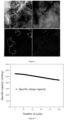
- Figure 2 is a scanning electron microscope (SEM) image of an anode material provided in Example 1 of the present disclosure
- Figure 3 is a transmission electron microscope (TEM) image of the anode material provided in Example 1 of the present disclosure.
- SEM scanning electron microscope
- TEM transmission electron microscope
- Figure 4 is a diagram showing electrochemical cycling of a half-cell prepared by the anode material provided in Example 1 of the present disclosure.
- the first-cycle specific charge capacity of the half-cell provided in Example 1 is as high as 2728 mAh/g, and the capacity retention rate over 100 cycles is 81.26%, showing excellent electrochemical performance.
- the anode material provided in the present disclosure comprises a silicon-based material, a carbon-coated tin nanowire and a carbon nanotube.
- the carbon-coated tin nanowire and the carbon nanotube both have a certain length, and have flexibility and elasticity to some extent. And they are mixed with the silicon-based material to form a three-dimensional conductive network structure, which can alleviate the volume effect of the anode material during the lithiation / delithiation process.
- the lithium-ion battery has a large specific capacity and high cycling stability.
- the anode material has a remarkable ionic conductivity and an excellent electronic conductivity, thereby obtaining a better conductivity.
Landscapes
- Chemical & Material Sciences (AREA)
- Chemical Kinetics & Catalysis (AREA)
- Electrochemistry (AREA)
- General Chemical & Material Sciences (AREA)
- Engineering & Computer Science (AREA)
- Manufacturing & Machinery (AREA)
- Materials Engineering (AREA)
- Composite Materials (AREA)
- Inorganic Chemistry (AREA)
- General Physics & Mathematics (AREA)
- Condensed Matter Physics & Semiconductors (AREA)
- Physics & Mathematics (AREA)
- Battery Electrode And Active Subsutance (AREA)
- Silicon Compounds (AREA)
- Secondary Cells (AREA)
Applications Claiming Priority (3)
| Application Number | Priority Date | Filing Date | Title |
|---|---|---|---|
| CN202210446202.3A CN114937772B (zh) | 2022-04-26 | 2022-04-26 | 负极材料、负极极片及锂离子电池 |
| CN202210446207.6A CN114944465A (zh) | 2022-04-26 | 2022-04-26 | 负极极片及电池 |
| PCT/CN2022/091231 WO2023206593A1 (zh) | 2022-04-26 | 2022-05-06 | 负极材料、负极极片及其制备方法和锂离子电池及其制备方法 |
Publications (2)
| Publication Number | Publication Date |
|---|---|
| EP4507014A1 true EP4507014A1 (de) | 2025-02-12 |
| EP4507014A4 EP4507014A4 (de) | 2025-10-15 |
Family
ID=88517074
Family Applications (1)
| Application Number | Title | Priority Date | Filing Date |
|---|---|---|---|
| EP22939436.6A Pending EP4507014A4 (de) | 2022-04-26 | 2022-05-06 | Negativelektrodenmaterial, negativelektrodenplatte und herstellungsverfahren dafür sowie lithium-ionen-batterie und herstellungsverfahren dafür |
Country Status (5)
| Country | Link |
|---|---|
| US (1) | US20250286044A1 (de) |
| EP (1) | EP4507014A4 (de) |
| JP (1) | JP2025514214A (de) |
| KR (1) | KR20250006951A (de) |
| WO (2) | WO2023206592A1 (de) |
Family Cites Families (14)
| Publication number | Priority date | Publication date | Assignee | Title |
|---|---|---|---|---|
| US7834349B2 (en) * | 2000-03-29 | 2010-11-16 | Georgia Tech Research Corporation | Silicon based nanospheres and nanowires |
| KR100759556B1 (ko) * | 2005-10-17 | 2007-09-18 | 삼성에스디아이 주식회사 | 음극 활물질, 그 제조 방법 및 이를 채용한 음극과 리튬전지 |
| KR100981909B1 (ko) * | 2008-04-15 | 2010-09-13 | 애경유화 주식회사 | 리튬 이차 전지용 음극 활물질, 그의 제조 방법 및 그를포함하는 리튬 이차 전지 |
| JP5448555B2 (ja) * | 2009-04-30 | 2014-03-19 | 古河電気工業株式会社 | リチウムイオン二次電池用負極、それを用いたリチウムイオン二次電池、リチウムイオン二次電池用の負極作製用のスラリー、リチウムイオン二次電池用負極の製造方法 |
| CN103887506A (zh) * | 2012-12-20 | 2014-06-25 | 华为技术有限公司 | 锂离子电池的负极材料及其制备方法和锂离子电池 |
| KR102143708B1 (ko) * | 2014-01-31 | 2020-08-11 | 가부시키가이샤 도요다 지도숏키 | 비수계 이차 전지용 부극 및 비수계 이차 전지, 부극 활물질 및 그 제조 방법, 나노 실리콘과 탄소층과 카티온성 폴리머층을 구비하는 복합체, 나노 실리콘과 탄소층으로 이루어지는 복합체의 제조 방법 |
| KR20180003577A (ko) * | 2015-06-22 | 2018-01-09 | 가부시키가이샤 히타치세이사쿠쇼 | 리튬 이온 이차 전지용 부극 활물질 및 리튬 이온 이차 전지 |
| JP2018147694A (ja) * | 2017-03-03 | 2018-09-20 | 株式会社豊田自動織機 | リチウムイオン二次電池 |
| JP2018166094A (ja) * | 2017-03-28 | 2018-10-25 | 株式会社豊田自動織機 | 負極材料及びその製造方法 |
| CN108206285B (zh) * | 2017-12-12 | 2021-08-24 | 中国科学院物理研究所 | 一种复合包覆的纳米锡负极材料及其制备方法和应用 |
| DE112019007985T5 (de) * | 2019-12-20 | 2022-10-13 | Institute Of Physics Chinese Academy Of Sciences | Nano-Zinn-Silizium-Verbundmaterial für negative Elektroden sowie Herstellungsverfahren und Verwendung davon |
| JP7611485B2 (ja) * | 2020-01-31 | 2025-01-10 | パナソニックIpマネジメント株式会社 | 非水電解質二次電池用負極、非水電解質二次電池および非水電解質二次電池用負極の製造方法 |
| US20210280871A1 (en) * | 2020-03-05 | 2021-09-09 | Global Graphene Group, Inc. | Conducting Polymer Network-Protected Nanowires of an Anode Active Material for Lithium-Ion Batteries |
| CN112072098B (zh) * | 2020-09-22 | 2021-06-29 | 福州大学 | 一种锂电池用纳米管状硅基材料及其制备方法 |
-
2022
- 2022-05-06 EP EP22939436.6A patent/EP4507014A4/de active Pending
- 2022-05-06 KR KR1020247039187A patent/KR20250006951A/ko active Pending
- 2022-05-06 JP JP2024563389A patent/JP2025514214A/ja active Pending
- 2022-05-06 US US18/859,567 patent/US20250286044A1/en active Pending
- 2022-05-06 WO PCT/CN2022/091228 patent/WO2023206592A1/zh not_active Ceased
- 2022-05-06 WO PCT/CN2022/091231 patent/WO2023206593A1/zh not_active Ceased
Also Published As
| Publication number | Publication date |
|---|---|
| JP2025514214A (ja) | 2025-05-02 |
| EP4507014A4 (de) | 2025-10-15 |
| KR20250006951A (ko) | 2025-01-13 |
| WO2023206592A1 (zh) | 2023-11-02 |
| US20250286044A1 (en) | 2025-09-11 |
| WO2023206593A1 (zh) | 2023-11-02 |
Similar Documents
| Publication | Publication Date | Title |
|---|---|---|
| JP7406638B2 (ja) | 負極シート及びその製造方法、二次電池、電池モジュール、電池パック並びに装置 | |
| EP3926713B1 (de) | Sekundärbatterie, verfahren zu ihrer herstellung und diese sekundärbatterie enthaltende vorrichtung | |
| EP4228034A1 (de) | Graphitverbundmaterial und herstellungsverfahren dafür, negativelektrodenplatte, sekundärbatterie, batteriemodul, batteriepack und stromgetriebene vorrichtung | |
| EP3800707B1 (de) | Sekundärbatterie und entsprechendes batteriemodul, batteriepack und gerät | |
| US12548773B2 (en) | Positive active material, positive electrode plate, lithium-ion battery, and electrical device | |
| EP3926707A1 (de) | Sekundärbatterie, verfahren zu ihrer herstellung und diese enthaltende vorrichtung | |
| EP3379615A1 (de) | Elektrodenmaterial für eine lithium-ionen-sekundärbatterie sowie lithium-ionen-sekundärbatterie | |
| JP7807137B2 (ja) | 負極およびこれを含む二次電池 | |
| EP4283706B1 (de) | Negativelektrodenplatte und anwendung davon | |
| EP4503173A1 (de) | Negativelektrodenplatte und herstellungsverfahren dafür, sekundärbatterie, batteriemodul, batteriepack und elektrische vorrichtung | |
| EP4184616A1 (de) | Negatives silicium-kohlenstoff-elektrodenmaterial, negative elektrodenplatte, sekundärbatterie, batteriemodul, batteriepack und elektrische vorrichtung | |
| KR102176590B1 (ko) | 리튬 이차전지용 음극 활물질의 제조방법 및 리튬 이차전지 | |
| JP2023523492A (ja) | マンガン酸リチウム正極活性材料及びそれを含む正極シート、二次電池、電池モジュール、電池パック及び電気装置 | |
| CN114497508A (zh) | 一种功率型人造石墨复合材料及其制备方法 | |
| WO2024148829A1 (zh) | 电池及用电装置 | |
| EP4567918A1 (de) | Negativelektrode und sekundärbatterie | |
| EP4033567A1 (de) | Kugelförmiges aktivmaterial auf kohlenstoffbasis, verfahren zur herstellung davon und anode und lithiumsekundärbatterie damit | |
| CN118248832B (zh) | 一种负极片、电池及用电设备 | |
| CN113366667A (zh) | 二次电池及其制造方法 | |
| EP4589682A1 (de) | Negativelektrodenmaterial, herstellungsverfahren dafür, sekundärbatterie und elektrische vorrichtung | |
| CN117038870A (zh) | 一种高能量密度兼顾快充负极材料的制备方法 | |
| CN116895756A (zh) | 用于全固态电池的包含簇状复合材料的电极浆料及其制造方法 | |
| EP4579786A1 (de) | Elektrode, sekundärbatterie und elektrische vorrichtung | |
| EP4109591A1 (de) | Anode und sekundärbatterie mit der anode | |
| EP4507014A1 (de) | Negativelektrodenmaterial, negativelektrodenplatte und herstellungsverfahren dafür sowie lithium-ionen-batterie und herstellungsverfahren dafür |
Legal Events
| Date | Code | Title | Description |
|---|---|---|---|
| STAA | Information on the status of an ep patent application or granted ep patent |
Free format text: STATUS: THE INTERNATIONAL PUBLICATION HAS BEEN MADE |
|
| PUAI | Public reference made under article 153(3) epc to a published international application that has entered the european phase |
Free format text: ORIGINAL CODE: 0009012 |
|
| STAA | Information on the status of an ep patent application or granted ep patent |
Free format text: STATUS: REQUEST FOR EXAMINATION WAS MADE |
|
| 17P | Request for examination filed |
Effective date: 20241106 |
|
| AK | Designated contracting states |
Kind code of ref document: A1 Designated state(s): AL AT BE BG CH CY CZ DE DK EE ES FI FR GB GR HR HU IE IS IT LI LT LU LV MC MK MT NL NO PL PT RO RS SE SI SK SM TR |
|
| DAV | Request for validation of the european patent (deleted) | ||
| DAX | Request for extension of the european patent (deleted) | ||
| A4 | Supplementary search report drawn up and despatched |
Effective date: 20250912 |
|
| RIC1 | Information provided on ipc code assigned before grant |
Ipc: H01M 4/02 20060101AFI20250908BHEP Ipc: H01M 4/04 20060101ALI20250908BHEP Ipc: H01M 4/36 20060101ALI20250908BHEP Ipc: H01M 4/38 20060101ALI20250908BHEP Ipc: H01M 4/48 20100101ALI20250908BHEP Ipc: H01M 4/587 20100101ALI20250908BHEP Ipc: H01M 4/62 20060101ALI20250908BHEP Ipc: H01M 10/0525 20100101ALI20250908BHEP Ipc: H01M 10/0562 20100101ALI20250908BHEP |