EP4507018A1 - Batteriezelle, batterie und elektrische vorrichtung - Google Patents
Batteriezelle, batterie und elektrische vorrichtung Download PDFInfo
- Publication number
- EP4507018A1 EP4507018A1 EP22961821.0A EP22961821A EP4507018A1 EP 4507018 A1 EP4507018 A1 EP 4507018A1 EP 22961821 A EP22961821 A EP 22961821A EP 4507018 A1 EP4507018 A1 EP 4507018A1
- Authority
- EP
- European Patent Office
- Prior art keywords
- battery cell
- active material
- electrode active
- positive electrode
- material layer
- Prior art date
- Legal status (The legal status is an assumption and is not a legal conclusion. Google has not performed a legal analysis and makes no representation as to the accuracy of the status listed.)
- Withdrawn
Links
Images


Classifications
-
- H—ELECTRICITY
- H01—ELECTRIC ELEMENTS
- H01M—PROCESSES OR MEANS, e.g. BATTERIES, FOR THE DIRECT CONVERSION OF CHEMICAL ENERGY INTO ELECTRICAL ENERGY
- H01M4/00—Electrodes
- H01M4/02—Electrodes composed of, or comprising, active material
- H01M4/13—Electrodes for accumulators with non-aqueous electrolyte, e.g. for lithium-accumulators; Processes of manufacture thereof
- H01M4/133—Electrodes based on carbonaceous material, e.g. graphite-intercalation compounds or CFx
-
- H—ELECTRICITY
- H01—ELECTRIC ELEMENTS
- H01M—PROCESSES OR MEANS, e.g. BATTERIES, FOR THE DIRECT CONVERSION OF CHEMICAL ENERGY INTO ELECTRICAL ENERGY
- H01M10/00—Secondary cells; Manufacture thereof
- H01M10/05—Accumulators with non-aqueous electrolyte
- H01M10/052—Li-accumulators
-
- H—ELECTRICITY
- H01—ELECTRIC ELEMENTS
- H01M—PROCESSES OR MEANS, e.g. BATTERIES, FOR THE DIRECT CONVERSION OF CHEMICAL ENERGY INTO ELECTRICAL ENERGY
- H01M10/00—Secondary cells; Manufacture thereof
- H01M10/05—Accumulators with non-aqueous electrolyte
- H01M10/056—Accumulators with non-aqueous electrolyte characterised by the materials used as electrolytes, e.g. mixed inorganic/organic electrolytes
- H01M10/0564—Accumulators with non-aqueous electrolyte characterised by the materials used as electrolytes, e.g. mixed inorganic/organic electrolytes the electrolyte being constituted of organic materials only
- H01M10/0566—Liquid materials
-
- H—ELECTRICITY
- H01—ELECTRIC ELEMENTS
- H01M—PROCESSES OR MEANS, e.g. BATTERIES, FOR THE DIRECT CONVERSION OF CHEMICAL ENERGY INTO ELECTRICAL ENERGY
- H01M10/00—Secondary cells; Manufacture thereof
- H01M10/05—Accumulators with non-aqueous electrolyte
- H01M10/056—Accumulators with non-aqueous electrolyte characterised by the materials used as electrolytes, e.g. mixed inorganic/organic electrolytes
- H01M10/0564—Accumulators with non-aqueous electrolyte characterised by the materials used as electrolytes, e.g. mixed inorganic/organic electrolytes the electrolyte being constituted of organic materials only
- H01M10/0566—Liquid materials
- H01M10/0567—Liquid materials characterised by the additives
-
- H—ELECTRICITY
- H01—ELECTRIC ELEMENTS
- H01M—PROCESSES OR MEANS, e.g. BATTERIES, FOR THE DIRECT CONVERSION OF CHEMICAL ENERGY INTO ELECTRICAL ENERGY
- H01M10/00—Secondary cells; Manufacture thereof
- H01M10/05—Accumulators with non-aqueous electrolyte
- H01M10/056—Accumulators with non-aqueous electrolyte characterised by the materials used as electrolytes, e.g. mixed inorganic/organic electrolytes
- H01M10/0564—Accumulators with non-aqueous electrolyte characterised by the materials used as electrolytes, e.g. mixed inorganic/organic electrolytes the electrolyte being constituted of organic materials only
- H01M10/0566—Liquid materials
- H01M10/0568—Liquid materials characterised by the solutes
-
- H—ELECTRICITY
- H01—ELECTRIC ELEMENTS
- H01M—PROCESSES OR MEANS, e.g. BATTERIES, FOR THE DIRECT CONVERSION OF CHEMICAL ENERGY INTO ELECTRICAL ENERGY
- H01M10/00—Secondary cells; Manufacture thereof
- H01M10/05—Accumulators with non-aqueous electrolyte
- H01M10/056—Accumulators with non-aqueous electrolyte characterised by the materials used as electrolytes, e.g. mixed inorganic/organic electrolytes
- H01M10/0564—Accumulators with non-aqueous electrolyte characterised by the materials used as electrolytes, e.g. mixed inorganic/organic electrolytes the electrolyte being constituted of organic materials only
- H01M10/0566—Liquid materials
- H01M10/0569—Liquid materials characterised by the solvents
-
- H—ELECTRICITY
- H01—ELECTRIC ELEMENTS
- H01M—PROCESSES OR MEANS, e.g. BATTERIES, FOR THE DIRECT CONVERSION OF CHEMICAL ENERGY INTO ELECTRICAL ENERGY
- H01M10/00—Secondary cells; Manufacture thereof
- H01M10/42—Methods or arrangements for servicing or maintenance of secondary cells or secondary half-cells
- H01M10/4235—Safety or regulating additives or arrangements in electrodes, separators or electrolyte
-
- H—ELECTRICITY
- H01—ELECTRIC ELEMENTS
- H01M—PROCESSES OR MEANS, e.g. BATTERIES, FOR THE DIRECT CONVERSION OF CHEMICAL ENERGY INTO ELECTRICAL ENERGY
- H01M4/00—Electrodes
- H01M4/02—Electrodes composed of, or comprising, active material
- H01M4/13—Electrodes for accumulators with non-aqueous electrolyte, e.g. for lithium-accumulators; Processes of manufacture thereof
-
- H—ELECTRICITY
- H01—ELECTRIC ELEMENTS
- H01M—PROCESSES OR MEANS, e.g. BATTERIES, FOR THE DIRECT CONVERSION OF CHEMICAL ENERGY INTO ELECTRICAL ENERGY
- H01M4/00—Electrodes
- H01M4/02—Electrodes composed of, or comprising, active material
- H01M4/13—Electrodes for accumulators with non-aqueous electrolyte, e.g. for lithium-accumulators; Processes of manufacture thereof
- H01M4/136—Electrodes based on inorganic compounds other than oxides or hydroxides, e.g. sulfides, selenides, tellurides, halogenides or LiCoFy
-
- H—ELECTRICITY
- H01—ELECTRIC ELEMENTS
- H01M—PROCESSES OR MEANS, e.g. BATTERIES, FOR THE DIRECT CONVERSION OF CHEMICAL ENERGY INTO ELECTRICAL ENERGY
- H01M50/00—Constructional details or processes of manufacture of the non-active parts of electrochemical cells other than fuel cells, e.g. hybrid cells
- H01M50/40—Separators; Membranes; Diaphragms; Spacing elements inside cells
- H01M50/489—Separators, membranes, diaphragms or spacing elements inside the cells, characterised by their physical properties, e.g. swelling degree, hydrophilicity or shut down properties
-
- H—ELECTRICITY
- H01—ELECTRIC ELEMENTS
- H01M—PROCESSES OR MEANS, e.g. BATTERIES, FOR THE DIRECT CONVERSION OF CHEMICAL ENERGY INTO ELECTRICAL ENERGY
- H01M50/00—Constructional details or processes of manufacture of the non-active parts of electrochemical cells other than fuel cells, e.g. hybrid cells
- H01M50/40—Separators; Membranes; Diaphragms; Spacing elements inside cells
- H01M50/489—Separators, membranes, diaphragms or spacing elements inside the cells, characterised by their physical properties, e.g. swelling degree, hydrophilicity or shut down properties
- H01M50/491—Porosity
-
- H—ELECTRICITY
- H01—ELECTRIC ELEMENTS
- H01M—PROCESSES OR MEANS, e.g. BATTERIES, FOR THE DIRECT CONVERSION OF CHEMICAL ENERGY INTO ELECTRICAL ENERGY
- H01M4/00—Electrodes
- H01M4/02—Electrodes composed of, or comprising, active material
- H01M2004/021—Physical characteristics, e.g. porosity, surface area
-
- H—ELECTRICITY
- H01—ELECTRIC ELEMENTS
- H01M—PROCESSES OR MEANS, e.g. BATTERIES, FOR THE DIRECT CONVERSION OF CHEMICAL ENERGY INTO ELECTRICAL ENERGY
- H01M4/00—Electrodes
- H01M4/02—Electrodes composed of, or comprising, active material
- H01M2004/026—Electrodes composed of, or comprising, active material characterised by the polarity
- H01M2004/027—Negative electrodes
-
- H—ELECTRICITY
- H01—ELECTRIC ELEMENTS
- H01M—PROCESSES OR MEANS, e.g. BATTERIES, FOR THE DIRECT CONVERSION OF CHEMICAL ENERGY INTO ELECTRICAL ENERGY
- H01M4/00—Electrodes
- H01M4/02—Electrodes composed of, or comprising, active material
- H01M2004/026—Electrodes composed of, or comprising, active material characterised by the polarity
- H01M2004/028—Positive electrodes
-
- H—ELECTRICITY
- H01—ELECTRIC ELEMENTS
- H01M—PROCESSES OR MEANS, e.g. BATTERIES, FOR THE DIRECT CONVERSION OF CHEMICAL ENERGY INTO ELECTRICAL ENERGY
- H01M2220/00—Batteries for particular applications
- H01M2220/20—Batteries in motive systems, e.g. vehicle, ship, plane
-
- H—ELECTRICITY
- H01—ELECTRIC ELEMENTS
- H01M—PROCESSES OR MEANS, e.g. BATTERIES, FOR THE DIRECT CONVERSION OF CHEMICAL ENERGY INTO ELECTRICAL ENERGY
- H01M2220/00—Batteries for particular applications
- H01M2220/30—Batteries in portable systems, e.g. mobile phone, laptop
-
- H—ELECTRICITY
- H01—ELECTRIC ELEMENTS
- H01M—PROCESSES OR MEANS, e.g. BATTERIES, FOR THE DIRECT CONVERSION OF CHEMICAL ENERGY INTO ELECTRICAL ENERGY
- H01M2300/00—Electrolytes
- H01M2300/0017—Non-aqueous electrolytes
- H01M2300/0025—Organic electrolyte
- H01M2300/0028—Organic electrolyte characterised by the solvent
- H01M2300/0037—Mixture of solvents
- H01M2300/004—Three solvents
-
- Y—GENERAL TAGGING OF NEW TECHNOLOGICAL DEVELOPMENTS; GENERAL TAGGING OF CROSS-SECTIONAL TECHNOLOGIES SPANNING OVER SEVERAL SECTIONS OF THE IPC; TECHNICAL SUBJECTS COVERED BY FORMER USPC CROSS-REFERENCE ART COLLECTIONS [XRACs] AND DIGESTS
- Y02—TECHNOLOGIES OR APPLICATIONS FOR MITIGATION OR ADAPTATION AGAINST CLIMATE CHANGE
- Y02E—REDUCTION OF GREENHOUSE GAS [GHG] EMISSIONS, RELATED TO ENERGY GENERATION, TRANSMISSION OR DISTRIBUTION
- Y02E60/00—Enabling technologies; Technologies with a potential or indirect contribution to GHG emissions mitigation
- Y02E60/10—Energy storage using batteries
Definitions
- the present application relates to the technical field of batteries, and particularly relates to a battery cell, a battery, and an electrical apparatus.
- batteries are widely used in electrical apparatuses, such as a vehicle.
- requirements for the rate performance and power performance of the batteries are increasingly high on the market.
- the batteries fail to have both good rate performance and good power performance.
- the present application provides a battery cell, a battery, and an electrical apparatus.
- the battery cell can have both good rate performance and good power performance.
- an example of the present application provides a battery cell, comprising a positive electrode plate, a negative electrode plate, a separator, and an electrolyte solution.
- the positive electrode plate comprises a positive electrode current collector and a positive electrode active material layer arranged on at least one side of the positive electrode current collector.
- the negative electrode plate comprises a negative electrode current collector and a negative electrode active material layer arranged on at least one side of the negative electrode current collector.
- the separator is arranged between the positive electrode plate and the negative electrode plate.
- the positive electrode active material layer, the negative electrode active material layer, the separator, and the electrolyte solution satisfy a relationship of: 50 M ⁇ ⁇ cm 2 ⁇ T 1 P 1 + T 2 P 2 + T 3 P 3 G ⁇ 300 M ⁇ cm 2 .
- T1 is a thickness of the positive electrode active material layer, in cm; and P1 is a porosity of the positive electrode active material layer.
- T2 is a thickness of the negative electrode active material layer, in cm; and P2 is a porosity of the negative electrode active material layer.
- T3 is a thickness of the separator, in cm; and P3 is a porosity of the separator.
- G is an ionic conductivity of the electrolyte solution at 25°C, in mS/cm.
- the positive electrode active material layer, the negative electrode active material layer, the separator, and the electrolyte solution satisfy the above relationship, and can contribute to ion transmission within the battery cell, so that the battery cell has low resistance at a high rate, thereby improving the power performance of the battery cell, and realizing both good rate performance and good power performance of the battery cell.
- a thickness T1 of the positive electrode active material layer satisfies: 0.0035 cm ⁇ T1 ⁇ 0.0055 cm; and optionally 0.0035 cm ⁇ T1 ⁇ 0.0045 cm.
- the thickness T1 of the positive electrode active material layer set within the above appropriate range can shorten the ion transmission path within the positive electrode active material layer, to further reduce the resistance of the battery cell, thereby improving the power performance of the battery cell.
- a porosity P1 of the positive electrode active material layer satisfies: 30% ⁇ P1 ⁇ 60%; and optionally, 40% ⁇ P1 ⁇ 60%.
- the porosity P1 of the positive electrode active material layer set within the above appropriate range can contribute to the ion transmission within the positive electrode active material layer, to further reduce the resistance of the battery cell, thereby improving the power performance of the battery cell.
- the positive electrode active material layer comprises a positive electrode active material, and a BET specific surface area S1 of the positive electrode active material satisfies: 8 m 2 /g ⁇ S1 ⁇ 12 m 2 /g.
- the BET specific surface area S1 of the positive electrode active material set within the above appropriate range can increase the ion transmission rate in the positive electrode active material layer, thereby further improving the power performance of the battery cell.
- a thickness T2 of the negative electrode active material layer satisfies: 0.003 cm ⁇ T2 ⁇ 0.005 cm; and optionally 0.0035 cm ⁇ T2 ⁇ 0.005 cm.
- the thickness T2 of the negative electrode active material layer set within the above appropriate range can shorten the ion transmission path within the negative electrode active material layer, to further reduce the resistance of the battery cell, thereby improving the power performance of the battery cell.
- a porosity P2 of the negative electrode active material layer satisfies: 30% ⁇ P2 ⁇ 60%; and optionally, 40% ⁇ P2 ⁇ 60%.
- the porosity P2 of the negative electrode active material layer set within the above appropriate range can contribute to the ion transmission within the negative electrode active material layer, to further reduce the resistance of the battery cell, thereby improving the power performance of the battery cell.
- the negative electrode active material layer comprises a negative electrode active material, and a BET specific surface area S2 of the negative electrode active material satisfies: 1.7 m 2 /g ⁇ S2 ⁇ 2.2 m 2 /g.
- the BET specific surface area S2 of the negative electrode active material set within the above appropriate range can increase the ion transmission rate in the negative electrode active material layer, thereby further improving the power performance of the battery cell.
- a thickness T3 of the separator satisfies: 0.0005 cm ⁇ T3 ⁇ 0.0015 cm.
- the thickness T3 of the separator set within the above range can shorten the ion transmission path within the separator, to further reduce the resistance of the battery cell, thereby providing the power performance thereof.
- a porosity P3 of the separator satisfies: 30% ⁇ P3 ⁇ 80%.
- the porosity P3 of the separator set within the above range can contribute to the ion transmission, increase the ion transmission rate, and then reduce the ions of the battery cell, thereby improving the power performance of the battery cell.
- a gas permeability of the separator is greater than or equal to 150 s/100 cm 3 .
- the gas permeability of the separator set within the above range can contribute to the ion transmission, increase the ion transmission rate, and then reduce the resistance of the battery cell, thereby improving the power performance of the battery cell.
- an ionic conductivity G of the electrolyte solution at 25°C satisfies: 13 mS/cm ⁇ G ⁇ 26 mS/cm; and optionally, 14 mS/cm ⁇ G ⁇ 25 mS/cm.
- the ionic conductivity G of the electrolyte solution at 25°C set within the above appropriate range can enhance the ion conductivity within the electrolyte solution, and further reduce the resistance of the battery cell, thereby further improving the power performance of the battery cell.
- a liquid retention coefficient N of the electrolyte solution satisfies: 3 g/Ah ⁇ N ⁇ 7 g/Ah.
- the liquid retention coefficient N of the electrolyte solution set within the above range not only can reduce the resistance of the battery cell to improve the power performance of the battery cell, but also can improve the cycling performance of the battery cell.
- the electrolyte solution comprises an electrolyte salt and an organic compound, and a viscosity ⁇ of the organic compound satisfies: 0.1 mPa ⁇ s-3.5 mPa ⁇ s.
- An organic compound with the electrolyte salt comprised in and the viscosity ⁇ of the electrolyte solution satisfying the above relationship makes the electrolyte solution have a high conductivity, and then can reduce the resistance of the battery cell, thereby further improving the power performance of the battery cell.
- a mass fraction A of the electrolyte salt satisfies: 10% ⁇ A ⁇ 20%, and a mass fraction B of the organic compound satisfies 30% ⁇ B ⁇ 70%.
- the mass fraction A of the electrolyte salt and the mass fraction B of the organic compound set within the above appropriate range respectively can reduce the viscosity of the electrolyte solution, improve the conductivity of the electrolyte solution, and then reduce the resistance of the battery cell, thereby further improving the resistance of the battery cell.
- the electrolyte salt includes a lithium salt; and optionally, the lithium salt is selected from the group consisting of lithium hexafluorophosphate, lithium bis(fluorosulfonyl)imide, and lithium bis(trifluoromethanesulphonyl)imide, or a combination thereof.
- the organic compound with low viscosity comprises a sulfone organic compound, an ether organic compound, an ester organic compound, and a nitrile organic compound; optionally, the sulfone organic compound is selected from dimethyl sulfoxide; optionally, the ether organic compound is selected from glycol dimethyl ether; optionally, the ester organic compound is selected from the group consisting of methyl formate, ethyl formate, methyl acetate, ethyl acetate, methyl acrylate, or a combination thereof; and optionally, the nitrle organic compound is selected from acetonitrile.
- the electrolyte solution further comprises a high temperature additive, and based on the mass of the electrolyte solution, a mass fraction C of the high temperature additive satisfies: 0.01% ⁇ C ⁇ 1%.
- the high temperature additive and the content thereof can contribute to forming a protective layer on a surface of an electrode plate, where the protective layer can be stable at a high temperature, and then contribute to protecting the electrode plate, so that the battery cell has good high temperature performance.
- the high temperature additive is selected from the group consisting of lithium tetrafluoroborate, lithium difluorophosphate, lithium fluorosulfonate, lithium sulphamate, or a combination thereof.
- the above high temperature additive can contribute to forming an inorganic protective layer to improve the mechanical strength of the protective layer, thereby further improving the high temperature performance of the battery.
- the electrolyte solution further comprises a film forming additive, and based on the mass of the electrolyte solution, a mass fraction D of the film forming additive satisfies: 1% ⁇ D ⁇ 5%.
- the film forming additive and the content thereof can contribute to improving the interfacial film stability, thereby improving the cycling performance of the battery cell.
- the film forming additive is selected from the group consisting of vinylene carbonate, fluoroethylene carbonate, vinylethylene carbonate, or a combination thereof.
- an example of the present application provides a battery, comprising the battery cell according to any one example in the first aspect of the present application.
- an example of the present application provides an electrical apparatus, comprising the battery cell according to any one example in the first aspect of the present application or the battery according to any one example in the second aspect of the present application.
- the technical terms such as “first” and “second” are only used for distinguishing between different objects, but cannot be understood as indicating or implying relative importance or implicitly indicating the number, specific order, or primary-secondary relationship of indicated technical features.
- the “plurality” means more than two, unless otherwise specifically defined.
- the examples of the present application provide a battery cell, a battery, and an electrical apparatus.
- the battery cell can have both good rate performance and good power performance.
- the electrical apparatus may be, e.g., a mobile phone, a portable device, a notebook computer, a ship, a spacecraft, a vehicle, an electric toy, and an electric tool.
- the vehicle may be a fuel vehicle, a gas vehicle, or a new energy vehicle.
- the new energy vehicle may be, e.g., an all-electric vehicle, a hybrid electric vehicle, or an extended range electric vehicle.
- the spacecraft includes, e.g., an airplane, a rocket, a space shuttle, and a spaceship.
- the electric toy includes a fixed or mobile electric toy, such as a game machine, an electric toy car, an electric toy ship, and an electric toy plane.
- the electric tool includes an electric metal cutting tool, an electric grinding tool, an electric assembling tool, and an electric tool for railway, such as an electric drill, an electric grinding machine, an electric wrench, an electric screwdriver, an electric hammer, an electric impact drill, a concrete vibrator, and an electric planer.
- an electric drill such as an electric drill, an electric grinding machine, an electric wrench, an electric screwdriver, an electric hammer, an electric impact drill, a concrete vibrator, and an electric planer.
- the above electrical apparatus is not specially limited in the examples of the present application.
- Fig. 1 shows a schematic structural diagram of a vehicle provided in some examples of the present application.
- the vehicle 1000 may be a fuel vehicle, a gas vehicle, or a new energy vehicle.
- the new energy vehicle may be, e.g., a all-electric vehicle, a hybrid vehicle, or a extended range electric vehicle.
- a battery 100 is provided within the vehicle 1000, where the battery 100 may be provided at the bottom or head or tail of the vehicle 1000.
- the battery 100 can be used to power the vehicle 1000, for example, the battery 100 can serve as an operating power source for the vehicle 1000.
- the vehicle 1000 may further include a controller 200 and a motor 300, where the controller 200 is configured to control the battery 100 to power the motor 300, for example, serve to satisfy operating power demand when the vehicle 1000 is starting, navigating, and running.
- the battery 100 not only can serve as an operating power source of the vehicle 1000, but also can serve as a driving power source of the vehicle 1000, to provide driving power for the vehicle 1000 in place of or partially in place of fuel or natural gas.
- Fig. 2 shows a schematic structural diagram of a battery provided in some examples of the present application.
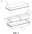
- Fig. 3 shows a schematic diagram of an exploded structure of the battery in Fig. 2 .
- the battery 100 in the present application refers to a battery comprising at least one battery cell 20. As shown in Fig. 2 and Fig. 3 , the battery 100 includes a box body 10 and a battery cell 20, where the battery cell 20 is accommodated within the box body 10.
- the box body 10 is configured to provide an accommodating space for the battery cell 20, and the box body 10 may adopt various structures.
- the box body 10 may include a first box body 11 and a second box body 12.
- the first box body 11 and the second box body 12 cover each other, such that the first box body 11 and the second box body 12 together define an accommodating space for accommodating the battery cell 20.
- the second box body 12 may be a hollow structure with one opening end, the first box body 11 may be a plate-like structure, and the first box body 11 covers on an opening side of the second box body 12, such that the first box body 11 and the second box body 12 together define the accommodating space; or the first box body 11 and the second box body 12 each may be a hollow structure with one opening side, and an opening side of the first box body 11 covers on the opening side of the second box body 12.
- the box body 10 formed by the first box body 11 and the second box body 12 may be of various shapes, such as a cylinder and a cuboid.
- the battery 100 there may be a plurality of battery cells 20, and there may be a series connection, or a parallel connection, or a parallel-series connection between the plurality of battery cells 20.
- the parallel-series connection means that there may be both the series connection and the parallel connection between the plurality of battery cells 20.
- the plurality of battery cells 20 can be directly connected together in series or in parallel or in parallel-series connection, and then the whole of the plurality of battery cells 20 is accommodated within the box body 10.
- Each of the battery cells 20 may be a secondary battery cell or a primary battery; or may be, but is not limited to, e.g., a lithium-ion secondary battery cell, a sodium-ion secondary battery cell, a magnesium-ion secondary battery cell, or a potassium-ion secondary battery cell.
- the battery cell 20 may present a cylindrical, flat, or cuboid shape, or other shapes.
- An example of the present application provides a battery cell, comprising a positive electrode plate, a negative electrode plate, a separator, and an electrolyte solution.
- the positive electrode plate comprises a positive electrode current collector and a positive electrode active material layer arranged on at least one side of the positive electrode current collector.
- the negative electrode plate comprises a negative electrode current collector and a negative electrode active material layer arranged on at least one side of the negative electrode current collector.
- the separator is arranged between the positive electrode plate and the negative electrode plate.
- the positive electrode active material layer, the negative electrode active material layer, the separator, and the electrolyte solution satisfy a relationship of: 50 M ⁇ ⁇ cm 2 ⁇ T 1 P 1 + T 2 P 2 + T 3 P 3 G ⁇ 300 M ⁇ ⁇ cm 2 .
- T1 is a thickness of the positive electrode active material layer, in cm; and P1 is a porosity of the positive electrode active material layer.
- T2 is a thickness of the negative electrode active material layer, in cm; and P2 is a porosity of the negative electrode active material layer.
- T3 is a thickness of the separator, in cm; and P3 is a porosity of the separator.
- G is an ionic conductivity of the electrolyte solution at 25°C, in mS/cm.
- the positive electrode current collector may be provided with a positive electrode active material layer on one surface, or may be provided with a positive electrode active material layer on each of two surfaces, or may be provided with a separator layer between a surface of the positive electrode current collector and the positive electrode active material layer, i.e., making the positive electrode active material not contact with the surface of the positive electrode current collector, which is not particularly defined here in the examples of the present application.
- the negative electrode current collector may be provided with a negative electrode active material layer on one surface, or may be provided with a negative electrode active material layer on each of two surfaces, or may be provided with a separator layer between a surface of the negative electrode current collector and the negative electrode active material layer, which is not particularly defined here in the examples of the present application.
- the thickness T1 of the positive electrode active material layer refers to a thickness of a single-sided positive electrode active material layer
- the thickness T2 of the negative electrode active material layer also refers to a thickness of a single-sided negative electrode active material layer.
- the porosity refers to a percentage of internal pore volume of a material in its total volume, and can be tested according to the method of GB/T 24586-2009.
- the ionic conductivity G of the electrolyte solution refers to a conductivity of the electrolyte solution at 25°C, which can be tested using a known method in the art, and using a test instrument, e.g., a LEICI conductivity meter.
- a real ion transmission path may not only be associated with the thickness of the active material layer and the thickness of the separator, but also be associated with the porosity of the active material layer and the porosity of the separator.
- the real ion transmission path in each layer is closer to a ratio of the thickness of each layer to its porosity, i.e., the thickness T1 and the porosity P1 of the positive electrode active material layer, the thickness T2 and the porosity P2 of the negative electrode active material layer, the thickness T3 and the porosity P3 of the separator, and the ionic conductivity G of the electrolyte solution satisfy the above relationship, thereby contributing to ion transmission within the battery cell, making the battery cell have low resistance at a high rate, improving the power performance of the battery cell, and realizing both good rate performance and good power performance of the battery cell.
- the thickness T1 of the positive electrode active material layer satisfies: 0.0035 cm ⁇ T1 ⁇ 0.0055 cm.
- the thickness T1 of the positive electrode active material layer set within the above appropriate range can shorten the ion transmission path within the positive electrode active material, to further reduce the resistance of the battery cell, thereby improving the power performance of the battery cell.
- the thickness T1 of the positive electrode active material layer satisfies: 0.0035 cm ⁇ T1 ⁇ 0.0045 cm, thereby further shortening the ion transmission path within the positive electrode active material layer, to not only improve the power performance of the battery cell, but also improve the cycling performance of the battery cell.
- the thickness T1 of the positive electrode active material layer may be, but is not limited to, 0.0035 cm, 0.0036 cm, 0.0037 cm, 0.0038 cm, 0.0039 cm, 0.0040 cm, 0.0041 cm, 0.0042 cm, 0.0043 cm, 0.0044 cm, 0.0045 cm, 0.0046 cm, 0.0047 cm, 0.0048 cm, 0.0049 cm, 0.0050 cm, 0.0051 cm, 0.0052 cm, 0.0053 cm, 0. 0054 cm, and 0.0055 cm.
- the porosity P1 of the positive electrode active material layer satisfies: 30% ⁇ P1 ⁇ 60%.
- the porosity P1 of the positive electrode active material layer set within the above appropriate range can contribute to the ion transmission within the positive electrode active material, to further reduce the resistance of the battery cell, thereby improving the power performance of the battery cell.
- the porosity P1 of the positive electrode active material layer satisfies: 40% ⁇ P1 ⁇ 60%, to further increase the ion transmission rate within the positive electrode active material layer, and further reduce the resistance of the battery cell, thereby improving the power performance of the battery cell.
- the porosity P1 of the positive electrode active material layer may be, but is not be limited to, 30%, 31%, 32%, 33%, 34%, 35%, 36%, 37%, 38%, 39%, 40%, 41%, 42%, 43%, 44%, 45%, 46%, 47%, 48%, 49%, 50%, 51%, 52%, 53%, 54%, 55%, 56%, 57%, 58%, 59%, and 60%.
- the positive electrode active material layer comprises a positive electrode active material, and a BET specific surface area S1 of the positive electrode active material satisfies: 8 m 2 /g ⁇ S1 ⁇ 12 m 2 /g.
- the BET specific surface area has a well-known meaning in the art, may be tested using a specific surface area analysis and test method by nitrogen adsorption, and is computed using the BET (Brunauer Emmett Teller) method, where the specific surface area analysis and test by nitrogen adsorption may be carried out using Tri-Star II specific surface area and porosity analyzer of Micrometrics Instruments Corporation.
- BET Brunauer Emmett Teller
- the BET specific surface area S1 of the positive electrode active material set within the above appropriate range not only can increase the ion transmission rate in the positive electrode active material layer to further improve the power performance of the battery cell, but also can reduce the contact area between the positive electrode active material and the electrolyte solution, and will decrease side reactions of the electrolyte solution on the surface of the positive electrode active material even at a high voltage or strong oxidability, thereby reducing the gas production and heat production, and improving the safety performance and cycling performance of the battery cell.
- the positive electrode active material may comprise the following materials or a combination thereof: a lithium-containing phosphate of olivine structure, a lithium transition metal oxide, and respective modified compound thereof.
- the present application is not limited to these materials, and other conventional materials useful as positive electrode active materials for batteries can also be used. These positive electrode active materials may be used alone or in combination of two or more thereof.
- lithium transition metal oxides may include, but are not limited to, a lithium cobalt oxide (e.g., LiCoO 2 ), a lithium nickel oxide (e.g., LiNiO 2 ), a lithium manganese oxide (e.g., LiMnO 2 or LiMn 2 O 4 ), a lithium nickel cobalt oxide, a lithium manganese cobalt oxide, a lithium nickel manganese oxide, a lithium nickel cobalt manganese oxide (e.g., LiNi 1/3 Co 1/3 Mn 1/3 O 2 (NCM333 for short), LiNi 0.5 Co 0.2 Mn 0.3 O 2 (NCM523 for short), LiNi 0.5 Co 0.25 Mn 0.25 O 2 (NCM211 for short), LiNi 0.6 Co 0.2 Mn 0.2 O 2 (NCM622 for short), LiNi 0.8 Co 0.1 Mn 0.1 O 2 (NCM811 for short), a lithium nickel cobalt aluminum oxide (e.g., LiNi 0.85 Co 0.15 Al
- lithium-containing phosphate of olivine structure may include, but are not limited to, lithium iron phosphate (such as LiFePO (also referred to as LFP)), a composite material of lithium iron phosphate and carbon, lithium manganese phosphate (such as LiMnPO 4 ), a composite material of lithium manganese phosphate and carbon, lithium iron manganese phosphate, and a composite material of lithium manganese iron phosphate and carbon, or a combination thereof.
- lithium iron phosphate such as LiFePO (also referred to as LFP)
- LiMnPO 4 lithium manganese phosphate
- the positive electrode active material layer may further comprise a conductive agent and a binder.
- Types of the conductive agent and the binder in the positive electrode active material layer are not specifically limited in the examples of the present application, and may be selected based on actual requirements.
- the conductive agent may be, but is not limited to, one or more of graphite, superconducting carbon, acetylene black, carbon black, Ketjen black, carbon dot, carbon nanotube, graphene, and carbon nanofiber.
- the binder may be, but is not limited to, one or more of styrene butadiene rubber (SBR), water-based acrylic resin, carboxymethylcellulose (CMC), polyvinylidene fluoride (PVDF), polytetrafluoroethylene (PTFE), polyvinyl butyral (PVB), ethylene-vinyl acetate copolymer (EVA), vinylidene fluoride-tetrafluoroethylene-propylene terpolymer, vinylidene fluoride-hexafluoropropylene-tetrafluoroethylene terpolymer, tetrafluoroethylene-hexafluoropropylene copolymer, fluorine-containing acrylic resin, and polyvinyl alcohol (PVA).
- SBR styrene butadiene rubber
- CMC carboxymethylcellulose
- PVDF polyvinylidene fluoride
- PTFE polytetrafluoroethylene
- PVB polyvinyl but
- a material such as a metal foil or a porous metal plate may be used as the positive electrode current collector.
- the material of the positive electrode current collector may be, but is not be limited to, a foil or a porous plate of a metal such as copper, nickel, titanium, or silver, or an alloy thereof.
- an aluminum foil is used as the positive electrode current collector.
- the positive electrode plate of the examples of the present application may be prepared using a conventional method in the art, for example, the positive electrode active material, the conductive agent, and the binder at a certain mass ratio are mixed by sufficiently stirring in an appropriate amount of NMP to form a uniform positive electrode slurry; and the positive electrode slurry is coated on the surface of the positive electrode current collector aluminum foil, which is dried, cold pressed, and cut to provide the positive electrode plate.
- the thickness T2 of the negative electrode active material layer satisfies: 0.003 cm ⁇ T2 ⁇ 0.005 cm.
- the thickness T2 of the negative electrode active material layer set within the above appropriate range can shorten the ion transmission path within the negative electrode active material layer to further reduce the resistance of the battery cell, thereby improving the power performance of the battery cell.
- the thickness T2 of the negative electrode active material layer satisfies: 0.0035 cm ⁇ T2 ⁇ 0.005 cm.
- the thickness T2 of the negative electrode active material set within the above appropriate range not only can reduce the resistance of the battery cell to improve the power performance of the battery cell, but also can improve the cycling performance of the battery cell.
- the thickness T2 of the negative electrode active material layer may be, but is not limited to, 0.003 cm, 0.0031 cm, 0.0032 cm, 0.0033 cm, 0.0034 cm, 0.0035 cm, 0.0036 cm, 0.0037 cm, 0.0038 cm, 0.0039 cm, 0.0040 cm, 0.0041 cm, 0.0042 cm, 0.0043 cm, 0.0044 cm, 0.0045 cm, 0.0046 cm, 0.0047 cm, 0.0048 cm, 0.0049 cm, and 0.0050 cm.
- the porosity P2 of the negative electrode active material layer satisfies: 30% ⁇ P2 ⁇ 60%.
- the porosity P2 of the negative electrode active material layer set within the above appropriate range can contribute to the ion transmission within the negative electrode active material, to further reduce the resistance of the battery cell, thereby improving the power performance of the battery cell.
- the porosity P2 of the negative electrode active material layer satisfies: 40% ⁇ P2 ⁇ 60%.
- the porosity P2 of the negative electrode active material layer set within the above appropriate range can further increase the ion transmission rate within the negative electrode active material layer, thereby further improving the power performance of the battery cell.
- the porosity P2 of the negative electrode active material layer may be, but is not be limited to, 30%, 31%, 32%, 33%, 34%, 35%, 36%, 37%, 38%, 39%, 40%, 41%, 42%, 43%, 44%, 45%, 46%, 47%, 48%, 49%, 50%, 51%, 52%, 53%, 54%, 55%, 56%, 57%, 58%, 59%, and 60%.
- the negative electrode active material layer comprises a negative electrode active material, and a BET specific surface area S2 of the negative electrode active material satisfies: 1.7 m 2 /g ⁇ S2 ⁇ 2.2 m 2 /g.
- the BET specific surface area S2 of the negative electrode active material set within the above appropriate range can increase the ion transmission rate in the negative electrode active material layer, thereby further improving the power performance of the battery cell.
- the negative electrode active material may comprise natural graphite, artificial graphite, mesocarbon microbead (MCMB for short), hard carbon, soft carbon, silicon, silicon-carbon complex, Li-Sn alloy, Li-Sn-O alloy, Sn, SnO, SnO 2 , lithiated TiO 2 -Li 4 Ti 5 O 12 of spinel structure, Li-Al alloy, or a combination thereof.
- MCMB mesocarbon microbead
- the negative electrode active material layer may further comprise a conductive agent and a binder.
- Types of the conductive agent and the binder in the negative electrode active material layer are not specifically limited in the examples of the present application, and may be selected based on actual requirements.
- the conductive agent may be, but is not limited to, one or more of graphite, superconducting carbon, acetylene black, carbon black, Ketjen black, carbon dot, carbon nanotube, graphene, and carbon nanofiber; and the binder may be, but is not limited to one or more of styrene butadiene rubber (SBR), polyvinylidene fluoride (PVDF), polytetrafluoroethylene (PTFE), polyvinyl butyral (PVB), water-based acrylic resin, and carboxymethyl cellulose (CMC).
- SBR styrene butadiene rubber
- PVDF polyvinylidene fluoride
- PTFE polytetrafluoroethylene
- PVB polyvinyl butyral
- water-based acrylic resin and carboxymethyl cellulose (CMC).
- a material such as a metal foil or a porous metal plate may be used as the negative electrode current collector.
- the material of the negative electrode current collector may be, but is not be limited to, a foil or a porous plate of a metal such as copper, nickel, titanium, or iron, or an alloy thereof.
- a copper foil is used as the negative electrode current collector.
- the negative electrode plate of the examples of the present application may be prepared using a conventional method in the art, for example, the negative electrode active material, the conductive agent, the binder, and a thickener at a certain mass ratio are dispersed in an appropriate amount of deionized water, a pore-forming agent is added, and the mixture is sufficiently stirred to form a uniformly dispersed negative electrode slurry; and the negative electrode slurry is coated on the surface of the negative electrode current collector copper foil, which is dried, cold pressed, and cut to provide the negative electrode plate.
- the thickness T3 of the separator satisfies: 0.0005 cm ⁇ T3 ⁇ 0.0015 cm.
- the thickness T3 of the separator set within the above range can shorten the ion transmission path within the separator, to further reduce the resistance of the battery cell, thereby providing the power performance thereof.
- the thickness T3 of the separator may be, but not limited to, 0.0005 cm, 0.0006 cm, 0.0007 cm, 0.0008 cm, 0.0009 cm, 0.0010 cm, 0.0011 cm, 0.0012 cm, 0.0013 cm, 0.0014 cm, and 0.0015 cm.
- the porosity P3 of the separator satisfies: 30% ⁇ P3 ⁇ 80%.
- the porosity P3 of the separator set within the above range can contribute to the ion transmission, increase the ion transmission rate, and then reduce the ions of the battery cell, thereby improving the power performance of the battery cell.
- the porosity P3 of the separator may be, but is not limited to, 30%, 31%, 32%, 33%, 34%, 35%, 36%, 37%, 38%, 39%, 40%, 41%, 42%, 43%, 44%, 45%, 46%, 47%, 48%, 49%, 50%, 51%, 52%, 53%, 54%, 55%, 56%, 57%, 58%, 59%, 60%, 61%, 62%, 63%, 64%, 65%, 66%, 67%, 68%, 69%, 70%, 71%, 72%, 73%, 74%, 75%, 76%, 77%, 78%, 79%, and 80%.
- a gas permeability of the separator is greater than or equal to 150 s/100 cm 3 .
- a method for measuring the gas permeability of the separator is not particularly limited, and the gas permeability may be measured using a method commonly used in the art.
- a non-restrictive example of the method for measuring the gas permeability is as follows: a test sample is made into a size of 4 cm ⁇ 4 cm in an environment at a temperature from 15°C to 28°C and a humidity of less than 80%, and a gas permeability value is directly measured using an air-permeability-tester according to Gurleytest (100 cc) method.
- the gas permeability of the separator set within the above range can contribute to the ion transmission, increase the ion transmission rate, and then reduce the resistance of the battery cell, thereby improving the power performance of the battery cell.
- the separator may be selected from the group consisting of polyethylene (PE), polypropylene (PP), polyvinylidene fluoride (PVDF), aramide, polyethylene terephthalate (PET), polytetrafluoroethylene (PTFE), polyacrylonitrile (PAN), polyimide (PI), polyamide, polyester, and a natural fiber, or a combination thereof.
- PE polyethylene
- PP polypropylene
- PVDF polyvinylidene fluoride
- PVDF aramide
- PET polyethylene terephthalate
- PTFE polytetrafluoroethylene
- PAN polyacrylonitrile
- PI polyimide
- polyamide polyamide
- polyester and a natural fiber, or a combination thereof.
- an ionic conductivity G of the electrolyte solution at 25°C satisfies: 13 mS/cm ⁇ G ⁇ 26 mS/cm.
- the ionic conductivity G of the electrolyte solution at 25°C set within the above appropriate range can enhance the ion conductivity within the electrolyte solution, and further reduce the resistance of the battery cell, thereby further improving the power performance of the battery cell.
- an ionic conductivity G of the electrolyte solution at 25°C satisfies: 14 mS/cm ⁇ G ⁇ 25 mS/cm.
- the ionic conductivity within the electrolyte solution can be further enhanced, to further reduce the resistance of the battery cell, thereby further improving the power performance of the battery cell.
- the ionic conductivity G of the electrolyte solution at 25°C may be, but is not limited to, 13 mS/cm, 14 mS/cm, 15 mS/cm, 16 mS/cm, 17 mS/cm, 18 mS/cm, 19 mS/cm, 20 mS/cm, 21 mS/cm, 22 mS/cm, 23 mS/cm, 24 mS/cm, 25 mS/cm, and 26 mS/cm.
- a liquid retention coefficient N of the electrolyte solution satisfies: 3 g/Ah ⁇ N ⁇ 7 g/Ah.
- the liquid retention coefficient N refers to a ratio of a liquid retention amount of the electrolyte solution to a first cycle discharge capacity of the battery cell.
- the liquid retention coefficient N of the electrolyte solution set within the above range not only can reduce the resistance of the battery cell to improve the power performance of the battery cell, but also can improve the cycling performance of the battery cell.
- the liquid retention coefficient N of the electrolyte solution may be, but is not limited to, 3 g/Ah, 4 g/Ah, 5 g/Ah, 6 g/Ah, and 7 g/Ah.
- the electrolyte solution comprises an electrolyte salt and an organic compound, and a viscosity ⁇ of the organic compound satisfies: 0.1 mPa ⁇ s-3.5 mPa ⁇ s.
- the viscosity of the organic compound may be tested with reference to GB/T 10247-2008 Methods of viscosity measurement, where a Bolefer (DV-2TLV) viscometer and a rotor No. 18 are used for testing at about 70 r/min.
- An organic compound with the electrolyte salt comprised in and the viscosity ⁇ of the electrolyte solution satisfying the above relationship makes the electrolyte solution have a high conductivity, and then can reduce the resistance of the battery cell, thereby further improving the power performance of the battery cell.
- a mass fraction A of the electrolyte salt satisfies: 10% ⁇ A ⁇ 20%, and a mass fraction B of the organic compound satisfies 30% ⁇ B ⁇ 70%.
- the mass fraction A of the electrolyte salt and the mass fraction B of the organic compound set within the above appropriate range respectively can reduce the viscosity of the electrolyte solution, improve the conductivity of the electrolyte solution, and then reduce the resistance of the battery cell, thereby further improving the resistance of the battery cell.
- the electrolyte salt includes a lithium salt.
- the lithium salt is selected from the group consisting of lithium hexafluorophosphate (LiPF 6 ), lithium bis(fluorosulfonyl)imide (LiFSI), and lithium bis(trifluoromethanesulphonyl)imide (LiTFSI), or a combination thereof.
- LiPF 6 lithium hexafluorophosphate
- LiFSI lithium bis(fluorosulfonyl)imide
- LiTFSI lithium bis(trifluoromethanesulphonyl)imide
- the organic compound comprises a sulfone organic compound, an ether organic compound, an ester organic compound, and a nitrile organic compound, or a combination thereof.
- the sulfone organic compound is selected from dimethyl sulfoxide (DMSO).
- the ether organic compound is selected from glycol dimethyl ether (DME).
- the ester organic compound is selected from the group consisting of methyl formate (MF), ethyl formate, methyl acetate (MA), ethyl acetate (EA), methyl acrylate, or a combination thereof.
- the nitrle organic compound is selected from acetonitrile (AN).
- the electrolyte solution further comprises a high temperature additive, and based on the mass of the electrolyte solution, a mass fraction C of the high temperature additive satisfies: 0.01% ⁇ C ⁇ 1%.
- the high temperature additive and the content thereof can contribute to forming a protective layer on a surface of an electrode plate, where the protective layer can be stable at a high temperature, and then contribute to protecting the electrode plate, so that the battery cell has good high temperature performance.
- the high temperature additive is selected from the group consisting of lithium tetrafluoroborate (LiBF 4 ), lithium difluorophosphate (LiPO 2 F 2 ), lithium fluorosulfonate (LiFSO 3 ), lithium sulphamate (LiH 2 NO 3 S), or a combination thereof.
- the above high temperature additive can contribute to forming an inorganic protective layer to improve the mechanical strength of the protective layer, thereby further improving the high temperature performance of the battery.
- the electrolyte solution further comprises a film forming additive, and based on the mass of the electrolyte solution, a mass fraction D of the film forming additive satisfies: 1% ⁇ D ⁇ 5%.
- the film forming additive and the content thereof can contribute to improving the interfacial film stability, thereby improving the cycling performance of the battery cell.
- the film forming additive is selected from the group consisting of vinylene carbonate, fluoroethylene carbonate, vinylethylene carbonate, or a combination thereof.
- Fig. 4 is a battery cell as an example
- Fig. 5 shows a schematic diagram of an exploded structure of the battery cell in Fig. 4 .
- the battery cell 20 includes a case 21, an electrode assembly 22, and a cover body assembly 23.
- the case 21 has a chamber accommodating the electrode assembly 22, and the cover body assembly 23 is configured to seal an opening of the case 21.
- the cover body assembly 23 comprises an end cover that is connected to the case 21 to form a shell of the battery cell 20.
- the electrode assembly 22 is provided within the case 21, and the case 21 is filled with an electrolyte.
- the end cover refers to a component that covers on the opening of the case 21 to isolate an internal environment of the battery cell 20 from an external environment.
- the shape of the end cover may be adapted to the shape of the case 21 to fit with the case 21.
- the end cover can be made of a material (such as an aluminum alloy) with certain hardness and strength, so that the end cover can hardly deform when being squeezed and collided, and so that the battery cell 20 not only can have higher structural strength, but also can have improved safety performance.
- a functional component such as an electrode terminal may be provided on the end cover. The electrode terminal may be configured to electrically connect to the electrode assembly 22, for outputting or inputting electrical energy of the battery cell 20.
- the end cover may also be provided with a pressure relief mechanism configured to relieve an internal pressure when the internal pressure or temperature of the battery cell 20 reaches a threshold.
- the end cover may also be made of a plurality of materials, such as copper, iron, aluminum, stainless steel, aluminum alloy, and plastic, which is not specially limited in the examples of the present application.
- an insulating member may be further provided on an inner side of the end cover. The insulating member may be configured to isolate an electrically connecting component within the case 21 from the end cover to reduce a short-circuit risk.
- the insulating member may be made of plastic, rubber, etc.
- the case 21 is an assembly configured to fit with the end cover to form the internal environment of the battery cell 20, where the formed internal environment may be used to accommodate the electrode assembly 22, the electrolyte, and other components.
- the case 21 and the end cover may be separate components, and an opening may be provided on the case 21, such that the end cover covers on the opening to form the internal environment of the battery cell 20.
- the end cover and the case 21 may also be integrated.
- the end cover and the case 21 may first form a common connection surface before other components enter the case, and when the inside of the case 21 is to be encapsulated, the end cover covers the case 21.
- the case 21 may be of various shapes and sizes, such as a cuboid shape, a cylindrical shape, or a hexagonal prism.
- the electrode assembly 22 is a component in the battery cell 20 where an electrochemical reaction occurs.
- the case 21 may comprise one or more electrode assemblies 22 therein.
- the electrode assembly 22 is mainly formed by winding or stacking of a positive electrode plate and a negative electrode plate, and a separator is generally provided between the positive electrode plate and the negative electrode plate.
- Parts of the positive electrode plate and the negative electrode plate having active materials constitute a main body part of the electrode assembly 22, and parts of the positive electrode plate and the negative electrode plate having no active material each form a tab.
- the positive tab and the negative tab may be located at one end of the main body part together or located at each end of the main body part respectively. In charging and discharging process of the battery, the positive electrode active material and the negative electrode active material react with the electrolyte solution, and the tab is connected to the electrode terminal to form a current circuit.
- the battery cell provided in the examples of the present application may be prepared using a conventional method.
- the following preparation method may be used: the positive electrode active material, the conductive agent, the binder are dispersed in a solvent (e.g., N-methylpyrrolidone, NMP for short) to form a uniform positive electrode slurry, and the positive electrode slurry is coated on two opposite surfaces of the positive electrode current collector, which is dried, cold pressed, and cut to obtain the positive electrode plate; the negative electrode active material, the conductive agent, the binder, and the thickener are dispersed in a solvent (e.g., deionized water), then a pore-forming agent is added, the mixture is stirred to obtain a uniformly dispersed negative electrode slurry, and the negative electrode slurry is coated on two opposite surfaces of the negative electrode current collector, which is dried, cold pressed, and cut to obtain the negative electrode plate; the positive electrode plate, the separator, and the negative electrode plate are sequentially stacked to obtain the electrode assembly, or
- the lithium iron phosphate (LFP) of olivine structure, polyvinylidene fluoride (PVDF), and carbon black (SP) at a mass ratio of 97:2:1 were mixed with a solvent, and the mixture was stirred to obtain a uniformly dispersed positive electrode slurry, which was uniformly coated on two surfaces of an aluminum foil.
- the aluminum foil was dried, cold pressed, and cut to provide the positive electrode plate.
- a polyethylene film was used as the separator.
- the positive electrode plate, the negative electrode plate, and the separator were made into an electrode assembly through a winding process or a stacking process, the electrode assembly was transferred into a case composed of an aluminum shell and an aluminum-plastic film, and then the electrolyte solution was injected into the case, which was encapsulated, to provide the battery cell after high temperature standing, formation, and capacity grading.
- the battery cell was discharged to 2.5V at a rate of 0.1C, and then disassembled to obtain the positive electrode plate, the negative electrode plate, and the separator.
- the positive electrode plate, the negative electrode plate, and the separator were left to stand still in a dry environment (humidity ⁇ 2%) for 24 h to volatilize the electrolyte solution.
- the test method of T2 is same as the test method of T1.
- a middle broken separator was measured with a spiral micrometer to obtain a thickness at a middle position of the separator, and a thickness at a next point was measured, until thickness data at 50 points were collected, to obtain an average value T3.
- the test was performed according to GB/T 24586-2009.
- the ionic conductivity of the electrolyte solution was tested using a LEICI conductivity meter at 25°C.
- the test was performed with reference to GB/T 19587-2004 Determination of the specific surface area of solids by gas adsorption-BET method, where the BET of the positive electrode plate was tested to be 10 m 2 /g, and the BET of the negative electrode plate was tested to be 1.9 m 2 /g in the examples and comparative examples.
- a test sample was made into a size of 4 cm ⁇ 4 cm in an environment at a temperature from 15°C to 28°C and a humidity of less than 80%, and a gas permeability value was directly measured using an air-permeability-tester according to Gurleytest (100 cc) method.
- Gurleytest 100 cc
- the battery cell was charged to 3.65V at a constant current of 5C, then charged to a current of 0.05C at a constant voltage, left to stand still for 10 min; discharged to 2.5V at a constant current of 3C, to obtain a discharge capacity Q1, and left to stand still for 10 min.
- a to-be-disassembled battery cell was weighed to obtain M 1 .
- the battery cell was disassembled to pour out the free electrolyte solution, dimethyl carbonate (DMC) was added into the case for extraction 3 times, the DMC residual mixture was poured out, the components such as the electrode assembly and the case were transferred into a drying oven to fully remove the DMC, and the residue was weighed to obtain M 2 . If a liquid retention amount is equal to M 1 -M 2 , the liquid retention coefficient N of the electrolyte solution is equal to (M 1 -M 2 )/Q1.
- DMC dimethyl carbonate
- Table 1 and Table 2 provide some parameters of the battery cell in Examples 1-28 and Comparative Example 1, respectively, where Z in Table 1 represents T 1 P 1 + T 2 P 2 + T 3 P 3 G , and Table 3 provides test results of the battery cell in Examples 1-28 and Comparative Example 1.
- Example 1 0.0045 40% 0.0035 40% 0.0012 40% 16.0 143.8
- Example 2 0.0045 40% 0.0035 40% 0.0012 40% 16.9 136.3
- Example 3 0.0045 40% 0.0035 40% 0.0012 40% 16.9 136.3
- Example 4 0.0045 40% 0.0035 40% 0.0012 40% 16.9 136.3
- Example 5 0.0045 40% 0.0035 40% 0.0012 40% 16.9 136.4
- Example 6 0.0045 40% 0.0035 40% 0.0012 40% 16.9 136.4
- Example 7 0.0045 40% 0.0035 40% 0.0012 40% 16.9 136.4
- Example 8 0.0045 40% 0.0035 40% 0.0012 40% 17.1 134.2
- Example 9 0.0045 40% 0.0035 40% 0.0012 40% 16.9 136.2
- Example 10 0.0045 40% 0.0035 40% 0.0012 40% 25.1 91.5
- Example 11 0.0045 40% 0.0035 40% 0.0012 40% 16.6 138.2
- Example 12 0.0045 40% 0.0035 40% 0.0012 40% 17.1 134.4
- Example 1 91.2% 82.1%
- Example 2 90.9% 95.6%
- Example 3 91.4% 95.7%
- Example 4 91.6% 95.7%
- Example 5 91.4% 96.1%
- Example 6 91.5% 96.3%
- Example 7 91.5% 96.2%
- Example 8 91.6% 96.7%
- Example 9 91.4% 96.6%
- Example 10 95.9% 98.9%
- Example 11 91.3% 95.9%
- Example 12 91.5% 96.2%
- Example 13 90.0% 95.4%
- Example 14 91.8% 96.3%
- Example 15 92.5% 96.7%
- Example 16 90.5% 95.6%
- Example 17 90.1% 95.4%
- Example 18 93.2% 97.0%
- Example 19 91.9% 96.4%
- Example 20 90.1% 95.4%
- Example 21 89.1% 94.9%
- Example 22 91.6% 96.2%
- Example 23 90.
- the thickness T1 and the porosity P1 of the positive electrode active material layer, the thickness T2 and the porosity P2 of the negative electrode active material layer, the thickness T3 and the porosity P3 of the separator, and the ionic conductivity G of the electrolyte solution satisfy the above relationship, so that the battery cell has low resistance at a high rate, thereby improving the power performance of the battery cell, and realizing both good rate performance and good power performance of the battery cell.
Landscapes
- Chemical & Material Sciences (AREA)
- Chemical Kinetics & Catalysis (AREA)
- Electrochemistry (AREA)
- General Chemical & Material Sciences (AREA)
- Engineering & Computer Science (AREA)
- Manufacturing & Machinery (AREA)
- Inorganic Chemistry (AREA)
- Condensed Matter Physics & Semiconductors (AREA)
- General Physics & Mathematics (AREA)
- Physics & Mathematics (AREA)
- Materials Engineering (AREA)
- Secondary Cells (AREA)
- Battery Electrode And Active Subsutance (AREA)
- Primary Cells (AREA)
- Cell Separators (AREA)
Applications Claiming Priority (1)
| Application Number | Priority Date | Filing Date | Title |
|---|---|---|---|
| PCT/CN2022/125523 WO2024077635A1 (zh) | 2022-10-14 | 2022-10-14 | 电池单体、电池及用电装置 |
Publications (2)
| Publication Number | Publication Date |
|---|---|
| EP4507018A1 true EP4507018A1 (de) | 2025-02-12 |
| EP4507018A4 EP4507018A4 (de) | 2025-07-30 |
Family
ID=88811492
Family Applications (1)
| Application Number | Title | Priority Date | Filing Date |
|---|---|---|---|
| EP22961821.0A Withdrawn EP4507018A4 (de) | 2022-10-14 | 2022-10-14 | Batteriezelle, batterie und elektrische vorrichtung |
Country Status (6)
| Country | Link |
|---|---|
| US (1) | US20250070274A1 (de) |
| EP (1) | EP4507018A4 (de) |
| JP (1) | JP2025514727A (de) |
| KR (1) | KR20240163723A (de) |
| CN (1) | CN117121218B (de) |
| WO (1) | WO2024077635A1 (de) |
Cited By (1)
| Publication number | Priority date | Publication date | Assignee | Title |
|---|---|---|---|---|
| EP4593147A4 (de) * | 2023-01-03 | 2026-04-08 | Contemporary Amperex Technology Hong Kong Ltd | Elektrolyt, batterie und elektrische vorrichtung |
Families Citing this family (4)
| Publication number | Priority date | Publication date | Assignee | Title |
|---|---|---|---|---|
| CN118213597A (zh) * | 2024-03-08 | 2024-06-18 | 宁德时代新能源科技股份有限公司 | 电池单体、电池及用电装置 |
| CN117878383B (zh) * | 2024-03-08 | 2024-09-13 | 宁德时代新能源科技股份有限公司 | 电池单体、电池和用电装置 |
| WO2026000395A1 (zh) * | 2024-06-28 | 2026-01-02 | 宁德时代新能源科技股份有限公司 | 电池单体、电池装置和用电装置 |
| CN120319993B (zh) * | 2025-06-13 | 2025-09-30 | 浙江锂威电子科技有限公司 | 一种电芯和电池 |
Family Cites Families (13)
| Publication number | Priority date | Publication date | Assignee | Title |
|---|---|---|---|---|
| JP3623391B2 (ja) * | 1999-03-15 | 2005-02-23 | 株式会社東芝 | 電池 |
| JP2009123497A (ja) * | 2007-11-14 | 2009-06-04 | Sony Corp | 非水電解液組成物及び非水電解液電池 |
| JP5678539B2 (ja) * | 2009-09-29 | 2015-03-04 | 三菱化学株式会社 | 非水系電解液電池 |
| JP2012069722A (ja) * | 2010-09-24 | 2012-04-05 | Denso Corp | 電気機器 |
| KR101551135B1 (ko) * | 2011-10-28 | 2015-09-07 | 아사히 가세이 가부시키가이샤 | 비수계 이차 전지 |
| JP2015088465A (ja) * | 2013-09-27 | 2015-05-07 | 日立マクセル株式会社 | 非水電解質二次電池 |
| MY174237A (en) * | 2016-08-10 | 2020-04-01 | Envision Aesc Japan Ltd | Non-aqueous electrolyte secondary battery |
| WO2020054866A1 (ja) * | 2018-09-14 | 2020-03-19 | 旭化成株式会社 | 非水系二次電池 |
| WO2020071056A1 (ja) * | 2018-10-03 | 2020-04-09 | Jfeケミカル株式会社 | ペースト組成物、二次電池用電極材料、二次電池用電極および二次電池 |
| CN111180737B (zh) * | 2019-05-31 | 2021-08-03 | 宁德时代新能源科技股份有限公司 | 锂离子二次电池、电芯及负极极片 |
| CN110943215B (zh) * | 2019-05-31 | 2020-12-04 | 宁德时代新能源科技股份有限公司 | 锂离子二次电池 |
| US20210344045A1 (en) * | 2019-06-28 | 2021-11-04 | Asahi Kasei Kabushiki Kaisha | Nonaqueous Electrolyte Solution and Nonaqueous Secondary Battery |
| CN119965326A (zh) * | 2020-12-24 | 2025-05-09 | 宁德时代新能源科技股份有限公司 | 锂离子二次电池及其制备方法、电池模块、电池包和装置 |
-
2022
- 2022-10-14 KR KR1020247035045A patent/KR20240163723A/ko active Pending
- 2022-10-14 CN CN202280012648.3A patent/CN117121218B/zh active Active
- 2022-10-14 JP JP2024561620A patent/JP2025514727A/ja active Pending
- 2022-10-14 WO PCT/CN2022/125523 patent/WO2024077635A1/zh not_active Ceased
- 2022-10-14 EP EP22961821.0A patent/EP4507018A4/de not_active Withdrawn
-
2024
- 2024-11-11 US US18/943,665 patent/US20250070274A1/en active Pending
Cited By (1)
| Publication number | Priority date | Publication date | Assignee | Title |
|---|---|---|---|---|
| EP4593147A4 (de) * | 2023-01-03 | 2026-04-08 | Contemporary Amperex Technology Hong Kong Ltd | Elektrolyt, batterie und elektrische vorrichtung |
Also Published As
| Publication number | Publication date |
|---|---|
| US20250070274A1 (en) | 2025-02-27 |
| CN117121218B (zh) | 2025-10-28 |
| CN117121218A (zh) | 2023-11-24 |
| KR20240163723A (ko) | 2024-11-19 |
| WO2024077635A1 (zh) | 2024-04-18 |
| EP4507018A4 (de) | 2025-07-30 |
| JP2025514727A (ja) | 2025-05-09 |
Similar Documents
| Publication | Publication Date | Title |
|---|---|---|
| US20220149437A1 (en) | Lithium-ion battery, and related battery module, battery pack, and apparatus | |
| EP4507018A1 (de) | Batteriezelle, batterie und elektrische vorrichtung | |
| EP3958362B1 (de) | Sekundärbatterie, batteriemodul, batteriepack und vorrichtung mit der sekundärbatterie | |
| US10700351B2 (en) | Nonaqueous electrolyte battery and battery pack | |
| EP4047711A1 (de) | Batteriemodul, batteriepack, elektronisches gerät sowie verfahren zur herstellung eines batteriemoduls und herstellungsverfahren | |
| EP4672404A1 (de) | Batteriezelle, batterie und elektrische vorrichtung | |
| JP3705728B2 (ja) | 非水電解液二次電池 | |
| JP2007087909A (ja) | 電池パック及び自動車 | |
| JP2008300180A (ja) | 非水電解質二次電池 | |
| US12500235B2 (en) | Secondary battery and device containing same | |
| US20260018694A1 (en) | Battery and electrical apparatus | |
| EP4235874A1 (de) | Sekundärbatterie, batteriemodul, batteriepack und elektrische vorrichtung | |
| EP4421916A1 (de) | Lithium-ionen-sekundärbatterie, batteriemodul, batteriepack und elektrische vorrichtung | |
| EP3913718B1 (de) | Sekundärbatterie und vorrichtung damit | |
| US20260018600A1 (en) | Positive electrode sheet, battery cell, battery, and electric device | |
| JP2008091041A (ja) | 非水電解質二次電池 | |
| EP4593147A1 (de) | Elektrolyt, batterie und elektrische vorrichtung | |
| WO2022163061A1 (ja) | 蓄電素子及び蓄電素子の使用方法 | |
| US20250337057A1 (en) | Battery cell, battery, and electric apparatus | |
| EP4668403A1 (de) | Zylindrische batteriezelle, batterie und elektrische vorrichtung | |
| US20230395866A1 (en) | Electrochemical cell with a specific liquid electrolyte | |
| EP4672437A1 (de) | Batteriezelle, batterie und elektrische vorrichtung | |
| CN121748566A (zh) | 电池单体、电池装置、用电设备 | |
| WO2024127079A1 (ja) | リチウム二次電池用電解液およびこれを用いたリチウム二次電池 | |
| KR20240021293A (ko) | 전해액, 이차전지, 배터리모듈, 배터리팩 및 전기기기 |
Legal Events
| Date | Code | Title | Description |
|---|---|---|---|
| STAA | Information on the status of an ep patent application or granted ep patent |
Free format text: STATUS: THE INTERNATIONAL PUBLICATION HAS BEEN MADE |
|
| PUAI | Public reference made under article 153(3) epc to a published international application that has entered the european phase |
Free format text: ORIGINAL CODE: 0009012 |
|
| STAA | Information on the status of an ep patent application or granted ep patent |
Free format text: STATUS: REQUEST FOR EXAMINATION WAS MADE |
|
| 17P | Request for examination filed |
Effective date: 20241106 |
|
| AK | Designated contracting states |
Kind code of ref document: A1 Designated state(s): AL AT BE BG CH CY CZ DE DK EE ES FI FR GB GR HR HU IE IS IT LI LT LU LV MC ME MK MT NL NO PL PT RO RS SE SI SK SM TR |
|
| A4 | Supplementary search report drawn up and despatched |
Effective date: 20250630 |
|
| RIC1 | Information provided on ipc code assigned before grant |
Ipc: H01M 4/13 20100101AFI20250624BHEP Ipc: H01M 10/0525 20100101ALI20250624BHEP Ipc: H01M 10/056 20100101ALI20250624BHEP Ipc: H01M 4/525 20100101ALI20250624BHEP Ipc: H01M 10/0567 20100101ALI20250624BHEP Ipc: H01M 10/0568 20100101ALI20250624BHEP Ipc: H01M 10/0569 20100101ALI20250624BHEP Ipc: H01M 4/02 20060101ALI20250624BHEP |
|
| STAA | Information on the status of an ep patent application or granted ep patent |
Free format text: STATUS: THE APPLICATION HAS BEEN WITHDRAWN |
|
| 18W | Application withdrawn |
Effective date: 20250908 |