EP4507112A1 - Batterie - Google Patents
Batterie Download PDFInfo
- Publication number
- EP4507112A1 EP4507112A1 EP23878832.7A EP23878832A EP4507112A1 EP 4507112 A1 EP4507112 A1 EP 4507112A1 EP 23878832 A EP23878832 A EP 23878832A EP 4507112 A1 EP4507112 A1 EP 4507112A1
- Authority
- EP
- European Patent Office
- Prior art keywords
- battery
- hole
- supporting block
- connector
- adapter
- Prior art date
- Legal status (The legal status is an assumption and is not a legal conclusion. Google has not performed a legal analysis and makes no representation as to the accuracy of the status listed.)
- Pending
Links
Images


Classifications
-
- H—ELECTRICITY
- H01—ELECTRIC ELEMENTS
- H01M—PROCESSES OR MEANS, e.g. BATTERIES, FOR THE DIRECT CONVERSION OF CHEMICAL ENERGY INTO ELECTRICAL ENERGY
- H01M50/00—Constructional details or processes of manufacture of the non-active parts of electrochemical cells other than fuel cells, e.g. hybrid cells
- H01M50/50—Current conducting connections for cells or batteries
- H01M50/528—Fixed electrical connections, i.e. not intended for disconnection
-
- H—ELECTRICITY
- H01—ELECTRIC ELEMENTS
- H01M—PROCESSES OR MEANS, e.g. BATTERIES, FOR THE DIRECT CONVERSION OF CHEMICAL ENERGY INTO ELECTRICAL ENERGY
- H01M50/00—Constructional details or processes of manufacture of the non-active parts of electrochemical cells other than fuel cells, e.g. hybrid cells
- H01M50/50—Current conducting connections for cells or batteries
- H01M50/531—Electrode connections inside a battery casing
- H01M50/533—Electrode connections inside a battery casing characterised by the shape of the leads or tabs
-
- H—ELECTRICITY
- H01—ELECTRIC ELEMENTS
- H01M—PROCESSES OR MEANS, e.g. BATTERIES, FOR THE DIRECT CONVERSION OF CHEMICAL ENERGY INTO ELECTRICAL ENERGY
- H01M50/00—Constructional details or processes of manufacture of the non-active parts of electrochemical cells other than fuel cells, e.g. hybrid cells
- H01M50/50—Current conducting connections for cells or batteries
- H01M50/531—Electrode connections inside a battery casing
- H01M50/536—Electrode connections inside a battery casing characterised by the method of fixing the leads to the electrodes, e.g. by welding
-
- H—ELECTRICITY
- H01—ELECTRIC ELEMENTS
- H01M—PROCESSES OR MEANS, e.g. BATTERIES, FOR THE DIRECT CONVERSION OF CHEMICAL ENERGY INTO ELECTRICAL ENERGY
- H01M50/00—Constructional details or processes of manufacture of the non-active parts of electrochemical cells other than fuel cells, e.g. hybrid cells
- H01M50/10—Primary casings; Jackets or wrappings
- H01M50/172—Arrangements of electric connectors penetrating the casing
- H01M50/174—Arrangements of electric connectors penetrating the casing adapted for the shape of the cells
- H01M50/176—Arrangements of electric connectors penetrating the casing adapted for the shape of the cells for prismatic or rectangular cells
-
- H—ELECTRICITY
- H01—ELECTRIC ELEMENTS
- H01M—PROCESSES OR MEANS, e.g. BATTERIES, FOR THE DIRECT CONVERSION OF CHEMICAL ENERGY INTO ELECTRICAL ENERGY
- H01M50/00—Constructional details or processes of manufacture of the non-active parts of electrochemical cells other than fuel cells, e.g. hybrid cells
- H01M50/60—Arrangements or processes for filling or topping-up with liquids; Arrangements or processes for draining liquids from casings
- H01M50/609—Arrangements or processes for filling with liquid, e.g. electrolytes
- H01M50/627—Filling ports
- H01M50/636—Closing or sealing filling ports, e.g. using lids
-
- Y—GENERAL TAGGING OF NEW TECHNOLOGICAL DEVELOPMENTS; GENERAL TAGGING OF CROSS-SECTIONAL TECHNOLOGIES SPANNING OVER SEVERAL SECTIONS OF THE IPC; TECHNICAL SUBJECTS COVERED BY FORMER USPC CROSS-REFERENCE ART COLLECTIONS [XRACs] AND DIGESTS
- Y02—TECHNOLOGIES OR APPLICATIONS FOR MITIGATION OR ADAPTATION AGAINST CLIMATE CHANGE
- Y02E—REDUCTION OF GREENHOUSE GAS [GHG] EMISSIONS, RELATED TO ENERGY GENERATION, TRANSMISSION OR DISTRIBUTION
- Y02E60/00—Enabling technologies; Technologies with a potential or indirect contribution to GHG emissions mitigation
- Y02E60/10—Energy storage using batteries
Definitions
- the present application relates to the technical field of batteries, and in particular to a battery.
- batteries are widely used in the fields of energy storage and power. With the popularization of application, the batteries have also derived a variety of structures. In the field of new energy batteries, batteries have a wide range of applications in the market due to their excellent safety performance. Batteries are commonly used electrochemical energy storage apparatus. In conventional battery structures, a first connector is formed by bending thin sheet metal, and has weak mechanical strength. The bent first connector is then welded to the housing of the battery to facilitate welding to the first adapter later.
- the present application provides a battery, so as to solve the technical problem that a first connector of the battery is easy to deform when a first adapter of the battery is welded to the first connector.
- the present application provides a battery, which includes:
- the supporting block is correspondingly arranged at the first connector.
- the supporting block is matched with the first connector, so that the supporting block may provide supporting function for the first connector. Therefore, the battery provided by the present application has a simple structure, which may effectively improve assembly efficiency and reduce the labor cost, thereby solving the technical problem of poor welding due to the deformation of the first connector when welding the first connector to the first adapter, causing the open circuit of the battery and leading to the scrapping of the battery.
- a projection of the supporting block in a thickness direction of the housing at least partially overlaps with a projection of the first adapter in the thickness direction of the housing, and/or, the projection of the supporting block in the thickness direction of the housing at least partially overlaps with a projection of the first side plate in the thickness direction of the housing.
- the first connector further includes a second side plate.
- the first side plate, the second side plate and the back plate form an accommodating part.
- the supporting block is arranged in the accommodating part.
- a surface of the supporting block facing away from the back plate is flush with surfaces of the first and second side plates facing away from the back plate.
- an inner wall of the first side plate facing the accommodating part and an inner wall of the second side plate facing the accommodating part are both in contact with the supporting block.
- the first adapter includes an adapter part, a welding part and a connecting part.
- the connecting part connects the adapter part to the welding part.
- the adapter part is connected to the first tab.
- the welding part is connected to the first side plate.
- a projection of the connecting part in a width direction of the battery at least partially overlaps with a projection of the supporting block in the width direction of the battery.
- the supporting block includes a first surface facing away from the back plate.
- the first adapter includes a second surface perpendicular to the welding part. The first surface is arranged to face the second surface.
- the second surface is located between the battery cell and the supporting block.
- the projection of the connecting part in the width direction of the battery completely overlaps with the projection of the supporting block in the width direction of the battery.
- the first connector is a plate structure
- the welding part of the first adapter is a plate structure
- the inner wall of the first side plate is in contact with the supporting block.
- the supporting block is an injection-molded structural member.
- the supporting block is provided with a through hole.
- the housing has a second through hole.
- the back plate has a third through hole. The through hole, the second through hole, and the third through hole are communicated.
- a diameter of the second through hole is smaller than a diameter of the third through hole.
- the diameter of the third through hole is the same as a diameter of the through hole.
- the battery further includes a reinforcing block.
- the reinforcing block is connected to an outer surface of the housing.
- the reinforcing block has a first through hole.
- the battery further includes a sealing sheet.
- the sealing sheet is connected to the reinforcing block and covers the first through hole.
- the reinforcing block is welded to the housing, and the first connector is arranged corresponding to the reinforcing block.
- a diameter of the first through hole is the same as the diameter of the second through hole, and the diameter of the third through hole is the same as the diameter of the through hole.
- the first connector is a negative connecting sheet
- the first tab is a negative tab
- the second tab is a positive tab
- the first tab and the second tab are located on a same side of the battery cell.
- the battery further includes a second adapter, a terminal post and an insulating assembly, where the second adapter is connected to the second tab and the terminal post is connected to the second adapter, the insulating assembly includes a first insulator and a second insulator, the first insulator is connected to the housing, the second insulator is arranged corresponding to the first insulator, and the second insulator is connected to the housing.
- an embodiment in the present application means that a specific feature, structure or characteristic described with reference to an embodiment can be included in at least one embodiment of the present application.
- the appearance of this phrase in various places in the specification does not necessarily refer to the same embodiment, nor is it an independent or alternative embodiment mutually exclusive with other embodiments. It is understood explicitly and implicitly by the skilled in the art that the embodiments described in the present application can be combined with other embodiments.
- the first connector is easy to deform when the first adapter of the battery is welded to the first connector in the related art. It was found through research by the inventor, the reason for this problem is that a certain pressure needs to be applied when the first adapter of the battery is welded to the first connector, so as to compress the first adapter and the first connector tightly.
- the first connector is formed by bending a thin metal sheet, and has weak strength. When the battery is assembled, it is easy to cause deformation of the first connector, which leads to poor welding between the first adapter and the first connector, and thus easily leads to the open circuit of the battery and then leads to the scrapping of the battery.
- the first adapter may also sink, which will cause the first adapter to pull the first tab of the battery cell, so that the first tab has a large stress.
- the finished product of the battery is subjected to vibration, it is easy for the first tab to be pulled off, which leads to the scrapping of the battery.
- the present application provides a battery, which includes a housing, a battery cell, a first connector, a first adapter and a supporting block. After connecting the first connector to the housing, the supporting block is correspondingly arranged at the first connector. The supporting block is matched with an accommodating part formed by the first connector, and thus provides a supporting function for the first connector.
- the battery provided by the present application has a simple structure, high assembly efficiency and low working strength, and can avoid the deformation of the first connector when the first adapter of the battery is welded to the first connector.
- a battery 1 of the embodiments of the present application may include a lithium ion secondary battery, a lithium sulfur battery or a sodium lithium ion battery, etc., and is not limited in the present application.
- the battery 1 may be a square battery, and is also not limited in the present application.
- Devices in the embodiments of the present application may be mobile devices such as vehicles, ships, small planes and etc.
- the vehicle of the present application may be a new energy vehicle.
- the new energy vehicle may be a pure battery electric vehicle, a hybrid vehicle or a range extended vehicle.
- the battery 1 may be used as a driving power source for vehicles, replacing or partially replacing fuel oil or natural gas to provide driving power for vehicles.
- the battery 1 provides electric energy for a driving motor.
- the driving motor is connected to wheels on the vehicle through a transmission mechanism so as to drive the vehicle to move.
- the battery 1 may be horizontally disposed at the bottom of the vehicle.
- a first connector 20 of the battery 1 is connected to a housing 10.
- a supporting block 40 is correspondingly arranged at the first connector 20.
- the supporting block 40 is matched with an accommodating part 20a formed by the first connector 20, to provide a supporting function for the first connector 20. In this way, the deformation resistance of the first connector 20 may be indirectly increased, so as to facilitate the welding and fixing between the first connector 20 and the first adapter 30.
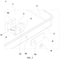
- the battery 1 of the present application includes a housing 10, a battery cell 70, a first connector 20, a first adapter 30 and a supporting block 40.
- the housing 10 includes an accommodating recess 10a.
- the battery cell 70 is located in the accommodating recess 10a.
- the battery cell 70 includes a first tab 71 and a second tab 72.
- the first connector 20 is arranged in the accommodating recess 10a.
- the first connector 20 includes a first side plate 21 and a back plate 23.
- the back plate 23 is connected to the housing 10.
- the first adapter 30 is respectively connected to the first tab 71 and the first side plate 21 of the first connector 20.
- the supporting block 40 is arranged on one side of the first side plate 21 facing away from the housing 10.
- the first side plate 21 of the first connector 20 is used to provide a supporting surface for welding to the first adapter 30, so as to facilitate the mutual fixing and welding between the first connector 20 and the first adapter 30.
- a contact surface between the back plate 23 of the first connector 20 and the housing 10 has a large area, which facilitates the welding between the first connector 20 and the housing 10 and is conducive to enhancing the fixing effect between the first connector 20 and the housing 10.
- the supporting block 40 is used to fill the accommodating part 20a of the first connector 20, thereby providing supporting function for the first connector 20.
- the first connector 20 may be a negative connecting sheet.
- the first adaptor 30 is connected to the first tab 71.
- the battery cell 70 may be a wound battery cell 70 or a laminated battery cell 70.
- the first tab 71 may be a negative tab.
- the second tab 72 may be a positive tab.
- the first tab 71 and the second tab 72 are located on a same side of the battery cell 70. In a width direction of the battery 1, the first tab 71 and the second tab 72 may be spaced apart. In some examples, the second tab 72 is welded to the battery cell 70.
- the supporting block 40 is correspondingly arranged at the first connector 20. The supporting block 40 is matched with the first connector 20, so that the supporting block 40 may provide a supporting function for the first connector 20.
- the first connector 20 is not easy to be deformed when stressed, thereby conducive to solving the problem of poor welding due to the deformation of the first connector 20 when welding the first connector 20 to the first adapter 30, which causes the open circuit of the battery 1 and then causes the scrapping of the battery 1.
- a projection of the supporting block 40 in a thickness direction of the housing 10 at least partially overlaps with a projection of the first adapter 30 in the thickness direction of the housing 10, and/or, the projection of the supporting block 40 in the thickness direction of the housing 10 at least partially overlaps with a projection of the first side plate 21 in the thickness direction of the housing 10.
- the projection of the supporting block 40 in a thickness direction of the housing 10 completely overlaps with a projection of the first adapter 30 in the thickness direction of the housing 10, and/or, the projection of the supporting block 40 in the thickness direction of the housing 10 completely overlaps with a projection of the first side plate 21 in the thickness direction of the housing 10.
- the first connector 20 further includes a second side plate 22.
- the first side plate 21, the second side plate 22 and the back plate 23 form an accommodating part 20a.
- the supporting block 40 is arranged in the accommodating part 20a. In the thickness direction of the housing 10, the first side plate 21 and the second side plate 22 are spaced apart.
- a surface of the supporting block 40 facing away from the back plate 23 is flush with surfaces of the first side plate 21 and the second side plate 22 that face away from the back plate 23.
- the supporting block 40 does not extend beyond the first connector 20, so that an overall structure formed by the supporting block 40 and the first connector 20 may avoid occupying more space, which is conducive to ensuring the battery 1 to have a high energy density.
- the supporting block 40 may be a plastic material, which is conducive to reducing a weight of the supporting block 40, thus reducing an overall weight of the battery 1.
- the supporting block 40 is an injection-molded structural member. After welding the first connector 20 to the housing 10, the first connector 20 and the housing 10 are partially injection-molded together.
- the supporting block 40 obtained after the injection molding may provide the supporting function for the first connector 20.
- the battery 1 of the present application has a simple structure, and the assembly efficiency can be effectively improved by adopting the injection molding filling method, and the cost of manual filling can be reduced.
- the first adapter 30 includes an adapter part 31, a welding part 32 and a connecting part 33.
- the connecting part 33 connects the adapter part 31 to the welding part 32, the adapter part 31 is connected to the first tab 71.
- the welding part 32 is connected to the first side plate 21.
- a projection of the connecting part 33 in a width direction of the battery 1 at least partially overlaps with a projection of the supporting block 40 in the width direction of the battery 1.
- the projection of the connecting part 33 in the width direction of the battery 1 completely overlaps with the projection of the supporting block 40 in the width direction of the battery 1.
- the first side plate 21 of the first connector 20 is a plate structure.
- the welding part 32 of the first adapter 30 is a plate structure.
- the first side plate 21 is rectangular.
- the welding part 32 is rectangular.
- a length of a long side of the first side plate 21 is equal to a length of a long side of the welding part 32.
- a length of a short side of the first side plate 21 is equal to a length of a short side of the welding part 32.
- the supporting block 40 includes a first surface 40b facing away from the back plate.
- the first adapter 30 includes a second surface 30a perpendicular to the welding part 32.
- the first surface 40b is arranged to face the second surface 30a.
- the welding part 32 does not occupy a space of the accommodating part 20a of the first connector 20 and does not interfere with the position of the supporting block 40.
- the intersection arrangement between the welding part 32 and the adapter part 31 is conducive to enhancing the welding firmness between the first connector 20 and the first adapter 30.
- the welding part 32 and the adapter part 31 are arranged perpendicular to each other. After the welding between the welding part 32 and the first side plate 21 is completed, a surface of the adapter part 31 may be parallel to a side of the supporting block 40 facing away from the back plate 23.
- FIG. 2 there is a gap 200a between the adapter part 31 and a surface of the supporting block 40 facing away from the back plate 23.
- the gap 200a between the adapter part 31 and a surface of the supporting block 40 facing away from the back plate 23 so that there is no positional interference between the supporting block 40 and the adapter part 31, allowing the adapter part 31 to have a movable space.
- the second surface 30a is located between the battery cell 70 and the supporting block 40.
- an inner wall of the first side plate 21 facing the accommodating part 20a is in contact with the supporting block 40, which is conducive to improving the integrity of the supporting block 40 and the first connector 20, effectively enhancing the supporting strength of the supporting block 40 to the first connector 20.
- an inner wall of the first side plate 21 facing the accommodating part 20a and an inner wall of the second side plate 22 facing the accommodating part 20a are both in contact with the supporting block 40.
- the inner wall of the first side plate 21 facing the accommodating part 20a is in contact with one side face of the supporting block 40, while the inner wall of the second side plate 22 facing the accommodating part 20a is in contact with the other side face of the supporting block 40, thereby being conductive to improving the integrity between the supporting block 40 and the first connector 20, to effectively enhance the supporting strength of the supporting block 40 to the first connector 20.
- the supporting block 40 is provided with a through hole 40a.
- the housing 10 has a second through hole 10b.
- the back plate has a third through hole 23a. The second through hole 10b and the third through hole 23a are communicated.
- a diameter of the second through hole 10b is smaller than diameters of the third through hole 23a and the through hole 40a.
- the third through hole 23a and the through hole 40a have the same diameter.
- the battery 1 further includes a reinforcing block 50.
- the reinforcing block 50 is connected to an outer surface of the housing 10.
- the reinforcing block 50 is conductive to enhancing the welding firmness between the first connector 20 and the housing 10, effectively solving the deformation of the first connector 20 when being pressed downward, and avoiding the dislocation between the first connector 20 and the housing 10, thus preventing cracks or notches from appearing at the welding position of the first connector 20 and the housing 10.
- the reinforcing block 50 is welded to the housing 10.
- the first connector 20 is arranged corresponding to the reinforcing block 50.
- the reinforcing block 50 has a first through hole 50a.
- the battery 1 further includes a sealing sheet 60.
- the sealing sheet 60 is connected to the reinforcing block 50 and covers the first through hole 50a.
- the sealing sheet 60 is connected to the reinforcing block 50.
- the first through hole 50a, the second through hole 10b, the third through hole 23a and the through hole 40a are communicated to form an injection hole 200b.
- the sealing sheet 60 may seal the injection hole 200b.
- centers of the first through hole 50a, the second through hole 10b, the third through hole 23a and the through hole 40a are on a same straight line. An electrolyte can be injected into the battery 1 through the injection hole 200b.
- the first through hole 50a and the second through hole 10b have the same diameter.
- the third through hole 23a and the through hole 40a have the same diameter.
- the diameter of the first through hole 50a is smaller than the diameter of the third through hole 23a.
- the first through hole 50a, the second through hole 10b, the third through hole 23a and the through hole 40a are circular holes.
- the first through hole 50a, the second through hole 10b, the third through hole 23a and the through hole 40a have equal area. Centers of the circles of the first through hole 50a, the second through hole 10b, the third through hole 23a and the through hole 40a are on a same straight line.
- the adapter part 31 there is a gap 200a between the adapter part 31 and a surface of the supporting block 40 facing away from the back plate 23.
- the through hole 40a of the supporting block 40 is communicated with the gap 200a between the adapter part 31 and the supporting block 40.
- the electrolyte When the electrolyte is injected through the injection hole 200b, the electrolyte may pass through the first through hole 50a, the second through hole 10b, the third through hole 23a, the through hole 40a and the gap 200a between the adapter part 31 and the supporting block 40.
- the adapter part 31 may block the electrolyte, which is conductive to reducing a flow rate of the electrolyte and also avoiding the electrolyte from impacting other structural members in the battery 1.
- the sealing sheet 60 is a circular sheet.
- the first through hole 50a of the reinforcing block 50 is a circular hole.
- An area of the sealing sheet 60 is larger than an opening area of the first through hole 50a.
- the sealing sheet 60 may be welded to the reinforcing block 50.
- the battery 1 further includes a battery cell 70.
- the battery cell 70 is arranged in the accommodating recess 10a.
- first adaptor 30 and the first tab 71 are connected by welding.
- a welding point between the first adapter 30 and the first tab 71 is located outside the first adapter 30, which is conductive to more effective welding between the first adapter 30 and the first tab 71.
- the adapter part 31 of the first adapter 30 may be welded to the first tab 71.
- the battery 1 further includes a second adapter 90, a terminal post 100, and an insulating assembly 110.
- the second adapter 90 is connected to the second tab 72.
- the terminal post 100 is connected to the second adapter 90.
- the insulating assembly 110 includes a first insulator 111 and a second insulator 112.
- the first insulator 111 is connected to the housing 10.
- the second insulator 112 is arranged corresponding to the first insulator 111.
- the second insulator 112 is connected to the housing 10.
- the battery 1 further includes a riveting sheet 120.
- the riveting piece 120 is connected to the second insulator 112.
- the battery 1 further includes a cover plate 80.
- the cover plate 80 is connected to the housing 10.
- the cover plate 80 covers the accommodating recess 10a.
- the battery cell 70 is arranged in the accommodating recess 10a.
- An area of the cover plate 80 is larger than a surface area of the battery cell 70.
- a depth of the accommodating recess 10a is larger than a thickness of the battery cell 70. This facilitates the cover plate 80 to cover the accommodating recess 10a more effectively, which is conductive to improving the overall sealing performance of the battery 1.
- the cover plate 80 may be welded to the housing 10.
- the housing 10 includes a bottom plate 11 and a side-wall plate 12.
- the bottom plate 11 and the side-wall plate 12 form an accommodation space for accommodating the battery cell 70.
- the first connector 20 is connected to the side-wall plate 12.
- the cover plate 80 is welded to the side-wall plate 12.
- a material of the housing 10 and a material of the cover plate 80 may be steel.
- Embodiments or implementations in this specification are described in a progressive way, and each embodiment focuses on the difference from other embodiments, and the same and similar parts between the embodiments can be referred to each other.
Landscapes
- Chemical & Material Sciences (AREA)
- Chemical Kinetics & Catalysis (AREA)
- Electrochemistry (AREA)
- General Chemical & Material Sciences (AREA)
- Connection Of Batteries Or Terminals (AREA)
- Battery Mounting, Suspending (AREA)
Applications Claiming Priority (2)
| Application Number | Priority Date | Filing Date | Title |
|---|---|---|---|
| CN202222792829.2U CN218586277U (zh) | 2022-10-21 | 2022-10-21 | 电池 |
| PCT/CN2023/116279 WO2024082837A1 (fr) | 2022-10-21 | 2023-08-31 | Batterie |
Publications (2)
| Publication Number | Publication Date |
|---|---|
| EP4507112A1 true EP4507112A1 (fr) | 2025-02-12 |
| EP4507112A4 EP4507112A4 (fr) | 2025-10-08 |
Family
ID=85374273
Family Applications (1)
| Application Number | Title | Priority Date | Filing Date |
|---|---|---|---|
| EP23878832.7A Pending EP4507112A4 (fr) | 2022-10-21 | 2023-08-31 | Batterie |
Country Status (4)
| Country | Link |
|---|---|
| US (1) | US20250062503A1 (fr) |
| EP (1) | EP4507112A4 (fr) |
| CN (1) | CN218586277U (fr) |
| WO (1) | WO2024082837A1 (fr) |
Families Citing this family (1)
| Publication number | Priority date | Publication date | Assignee | Title |
|---|---|---|---|---|
| CN218586277U (zh) * | 2022-10-21 | 2023-03-07 | 珠海冠宇电池股份有限公司 | 电池 |
Family Cites Families (9)
| Publication number | Priority date | Publication date | Assignee | Title |
|---|---|---|---|---|
| CN207743288U (zh) * | 2018-01-31 | 2018-08-17 | 宁德时代新能源科技股份有限公司 | 电池模组 |
| CN209766569U (zh) * | 2019-06-19 | 2019-12-10 | 宁德时代新能源科技股份有限公司 | 二次电池及电池模组 |
| CN216054941U (zh) * | 2021-08-31 | 2022-03-15 | 宁德时代新能源科技股份有限公司 | 电池单体、电池以及用电设备 |
| CN114614208A (zh) * | 2022-03-26 | 2022-06-10 | 珠海冠宇电池股份有限公司 | 电池 |
| CN217507616U (zh) * | 2022-03-26 | 2022-09-27 | 珠海冠宇电池股份有限公司 | 电池 |
| CN114597610A (zh) * | 2022-03-26 | 2022-06-07 | 珠海冠宇电池股份有限公司 | 电池 |
| CN217062312U (zh) * | 2022-04-20 | 2022-07-26 | 中创新航科技股份有限公司 | 电池盖板组件及电池 |
| CN217589145U (zh) * | 2022-06-30 | 2022-10-14 | 珠海冠宇电池股份有限公司 | 一种电池 |
| CN218586277U (zh) * | 2022-10-21 | 2023-03-07 | 珠海冠宇电池股份有限公司 | 电池 |
-
2022
- 2022-10-21 CN CN202222792829.2U patent/CN218586277U/zh active Active
-
2023
- 2023-08-31 EP EP23878832.7A patent/EP4507112A4/fr active Pending
- 2023-08-31 WO PCT/CN2023/116279 patent/WO2024082837A1/fr not_active Ceased
-
2024
- 2024-11-06 US US18/938,409 patent/US20250062503A1/en active Pending
Also Published As
| Publication number | Publication date |
|---|---|
| EP4507112A4 (fr) | 2025-10-08 |
| CN218586277U (zh) | 2023-03-07 |
| US20250062503A1 (en) | 2025-02-20 |
| WO2024082837A1 (fr) | 2024-04-25 |
Similar Documents
| Publication | Publication Date | Title |
|---|---|---|
| EP3836297B1 (fr) | Batterie secondaire, module de batterie, bloc-batterie, dispositif et son procédé de fabrication | |
| CN108598353B (zh) | 充电电池 | |
| US20220238945A1 (en) | End cover assembly, battery cell, battery pack, apparatus and liquid-injection method | |
| US20240128487A1 (en) | Battery | |
| CN115347287A (zh) | 电池顶盖、电池及电池制造方法 | |
| US20250062503A1 (en) | Battery | |
| CN220692266U (zh) | 电芯成组模块及电池包 | |
| CN219717145U (zh) | 电池包上盖、电池包以及车辆 | |
| CN218385498U (zh) | 电池及用电设备 | |
| US20240222819A1 (en) | Battery, battery cell, battery module, electrical device, end cap assembly and manufacturing method for battery | |
| CN219457936U (zh) | 极耳支架、电池单体、电池及用电装置 | |
| WO2026045083A1 (fr) | Logement de batterie, batterie secondaire et procédé de fabrication associé | |
| CN219779095U (zh) | 电池箱体、电池以及用电装置 | |
| CN219106333U (zh) | 连接结构、盖板组件及电池 | |
| CN216980824U (zh) | 电池 | |
| CN214227029U (zh) | 电芯安装板及电芯模组 | |
| CN116031589A (zh) | 电池单体、电池包、电动车以及加工方法 | |
| CN223066302U (zh) | 电芯及电池包 | |
| CN219040593U (zh) | 一种电池顶盖及电池 | |
| CN224123485U (zh) | 一种单体电池及电池包 | |
| CN219811635U (zh) | 锂离子电池 | |
| CN224191054U (zh) | 电池盖板及电池单体 | |
| CN222601294U (zh) | 电池装置和用电设备 | |
| CN223390650U (zh) | 下塑胶、单体电池及用电设备 | |
| CN218939907U (zh) | 软包电芯模组及动力电池包总成 |
Legal Events
| Date | Code | Title | Description |
|---|---|---|---|
| STAA | Information on the status of an ep patent application or granted ep patent |
Free format text: STATUS: THE INTERNATIONAL PUBLICATION HAS BEEN MADE |
|
| PUAI | Public reference made under article 153(3) epc to a published international application that has entered the european phase |
Free format text: ORIGINAL CODE: 0009012 |
|
| STAA | Information on the status of an ep patent application or granted ep patent |
Free format text: STATUS: REQUEST FOR EXAMINATION WAS MADE |
|
| 17P | Request for examination filed |
Effective date: 20241107 |
|
| AK | Designated contracting states |
Kind code of ref document: A1 Designated state(s): AL AT BE BG CH CY CZ DE DK EE ES FI FR GB GR HR HU IE IS IT LI LT LU LV MC ME MK MT NL NO PL PT RO RS SE SI SK SM TR |
|
| A4 | Supplementary search report drawn up and despatched |
Effective date: 20250905 |
|
| RIC1 | Information provided on ipc code assigned before grant |
Ipc: H01M 50/531 20210101AFI20250901BHEP Ipc: H01M 50/586 20210101ALI20250901BHEP Ipc: H01M 50/536 20210101ALI20250901BHEP Ipc: H01M 50/528 20210101ALI20250901BHEP Ipc: H01M 50/533 20210101ALI20250901BHEP |
|
| DAV | Request for validation of the european patent (deleted) | ||
| DAX | Request for extension of the european patent (deleted) |