EP4507182A1 - Elektrischer wechselstrom-gleichstrom-schaltwandler - Google Patents
Elektrischer wechselstrom-gleichstrom-schaltwandler Download PDFInfo
- Publication number
- EP4507182A1 EP4507182A1 EP23382841.7A EP23382841A EP4507182A1 EP 4507182 A1 EP4507182 A1 EP 4507182A1 EP 23382841 A EP23382841 A EP 23382841A EP 4507182 A1 EP4507182 A1 EP 4507182A1
- Authority
- EP
- European Patent Office
- Prior art keywords
- input
- output
- bridge
- power converter
- leg
- Prior art date
- Legal status (The legal status is an assumption and is not a legal conclusion. Google has not performed a legal analysis and makes no representation as to the accuracy of the status listed.)
- Withdrawn
Links
Images




Classifications
-
- H—ELECTRICITY
- H02—GENERATION; CONVERSION OR DISTRIBUTION OF ELECTRIC POWER
- H02M—APPARATUS FOR CONVERSION BETWEEN AC AND AC, BETWEEN AC AND DC, OR BETWEEN DC AND DC, AND FOR USE WITH MAINS OR SIMILAR POWER SUPPLY SYSTEMS; CONVERSION OF DC OR AC INPUT POWER INTO SURGE OUTPUT POWER; CONTROL OR REGULATION THEREOF
- H02M1/00—Details of apparatus for conversion
- H02M1/42—Circuits or arrangements for compensating for or adjusting power factor in converters or inverters
- H02M1/4208—Arrangements for improving power factor of AC input
- H02M1/4258—Arrangements for improving power factor of AC input using a single converter stage both for correction of AC input power factor and generation of a regulated and galvanically isolated DC output voltage
-
- H—ELECTRICITY
- H02—GENERATION; CONVERSION OR DISTRIBUTION OF ELECTRIC POWER
- H02M—APPARATUS FOR CONVERSION BETWEEN AC AND AC, BETWEEN AC AND DC, OR BETWEEN DC AND DC, AND FOR USE WITH MAINS OR SIMILAR POWER SUPPLY SYSTEMS; CONVERSION OF DC OR AC INPUT POWER INTO SURGE OUTPUT POWER; CONTROL OR REGULATION THEREOF
- H02M1/00—Details of apparatus for conversion
- H02M1/0048—Circuits or arrangements for reducing losses
- H02M1/0054—Transistor switching losses
- H02M1/0058—Transistor switching losses by employing soft switching techniques, i.e. commutation of transistors when applied voltage is zero or when current flow is zero
-
- H—ELECTRICITY
- H02—GENERATION; CONVERSION OR DISTRIBUTION OF ELECTRIC POWER
- H02M—APPARATUS FOR CONVERSION BETWEEN AC AND AC, BETWEEN AC AND DC, OR BETWEEN DC AND DC, AND FOR USE WITH MAINS OR SIMILAR POWER SUPPLY SYSTEMS; CONVERSION OF DC OR AC INPUT POWER INTO SURGE OUTPUT POWER; CONTROL OR REGULATION THEREOF
- H02M1/00—Details of apparatus for conversion
- H02M1/14—Arrangements for reducing ripples from DC input or output
- H02M1/15—Arrangements for reducing ripples from DC input or output using active elements
-
- H—ELECTRICITY
- H02—GENERATION; CONVERSION OR DISTRIBUTION OF ELECTRIC POWER
- H02M—APPARATUS FOR CONVERSION BETWEEN AC AND AC, BETWEEN AC AND DC, OR BETWEEN DC AND DC, AND FOR USE WITH MAINS OR SIMILAR POWER SUPPLY SYSTEMS; CONVERSION OF DC OR AC INPUT POWER INTO SURGE OUTPUT POWER; CONTROL OR REGULATION THEREOF
- H02M7/00—Conversion of AC power input into DC power output; Conversion of DC power input into AC power output
- H02M7/02—Conversion of AC power input into DC power output without possibility of reversal
- H02M7/04—Conversion of AC power input into DC power output without possibility of reversal by static converters
- H02M7/12—Conversion of AC power input into DC power output without possibility of reversal by static converters using discharge tubes with control electrode or semiconductor devices with control electrode
- H02M7/21—Conversion of AC power input into DC power output without possibility of reversal by static converters using discharge tubes with control electrode or semiconductor devices with control electrode using devices of a triode or transistor type requiring continuous application of a control signal
- H02M7/217—Conversion of AC power input into DC power output without possibility of reversal by static converters using discharge tubes with control electrode or semiconductor devices with control electrode using devices of a triode or transistor type requiring continuous application of a control signal using semiconductor devices only
- H02M7/219—Conversion of AC power input into DC power output without possibility of reversal by static converters using discharge tubes with control electrode or semiconductor devices with control electrode using devices of a triode or transistor type requiring continuous application of a control signal using semiconductor devices only in a bridge configuration
-
- Y—GENERAL TAGGING OF NEW TECHNOLOGICAL DEVELOPMENTS; GENERAL TAGGING OF CROSS-SECTIONAL TECHNOLOGIES SPANNING OVER SEVERAL SECTIONS OF THE IPC; TECHNICAL SUBJECTS COVERED BY FORMER USPC CROSS-REFERENCE ART COLLECTIONS [XRACs] AND DIGESTS
- Y02—TECHNOLOGIES OR APPLICATIONS FOR MITIGATION OR ADAPTATION AGAINST CLIMATE CHANGE
- Y02B—CLIMATE CHANGE MITIGATION TECHNOLOGIES RELATED TO BUILDINGS, e.g. HOUSING, HOUSE APPLIANCES OR RELATED END-USER APPLICATIONS
- Y02B70/00—Technologies for an efficient end-user side electric power management and consumption
- Y02B70/10—Technologies improving the efficiency by using switched-mode power supplies [SMPS], i.e. efficient power electronics conversion e.g. power factor correction or reduction of losses in power supplies or efficient standby modes
Definitions
- the present invention generally relates to the field of electrical power converters. More specifically, the invention relates to an AC-DC switch mode electrical power converter with Power Factor Correction and tight regulation of the output voltage.
- the first power stage takes an input current nearly proportional to the AC supply input voltage, so that power factor is close to one.
- a sinusoidal input voltage e.g. 50Hz or 60Hz
- the current is also sinusoidal.
- the power taken from the AC input voltage source is pulsating between 0 and twice the output power P.
- the product of a sine waveform (input voltage) multiplied by another sine waveform (the input current) yields a squared sine, which is a cosine waveform of twice the line frequency, e.g. 100Hz or 120Hz, plus a mean value, which is the DC output power.
- the storage capacitor must have a twice-the-line-frequency ripple, because it is storing and releasing energy at twice the line frequency. It is not a question of control, but a question of power and energy processing.
- the second power stage is a DC-DC converter, typically supplied from the output capacitor of the first PFC stage, which is typically the storage capacitor Cs.
- the typical structure of an AC-DC converter with PFC is a typical 4-diode bridge followed by a variable gain DC-DC converter, referred to as PFC DC-DC converter.
- the diode bridge converts the negative voltage of the AC input voltage into a positive voltage so that the absolute value of a sinusoid (so called a rectified voltage) is applied to the PFC DC-DC converter.
- This PFC DC-DC converter is therefore supplied by an input voltage that changes from 0V to 110 ⁇ 2 V or 220 ⁇ 2 V , depending on the geographical location.
- a broadly used alternative, and more efficient approach is to integrate the functionality of the diode bridge with the PFC DC-DC converter in the so called "Bridgeless boost PFC DC-DC converter". It is more efficient because the input current flows through two power switches in series rather than through at least three power switches. Conduction losses are therefore lower.
- the PFC stage is a "bridgeless half-bridge boost" PFC power converter as described by Ramesh Srinivasan et al. "A unity power factor converter using a half-bridge topology " [2], with the advantage that input current only flows through one power switch, further reducing conduction losses, at the expense of higher voltage in the storage capacitor.
- the switching leg of the half-bridge is replaced by a “flying capacitor” or a “switched capacitor” leg to reduce the voltage applied to the power switches.
- the role of the DC-DC converter in the second stage is to regulate the output voltage eliminating the "low frequency ripple" (typically 100Hz or 120Hz) present in the storage capacitor.
- This power converter operates at a switching frequency (typically >1 00kHz) which is orders of magnitude higher than line frequency.
- the second stage belongs to the family of the "Dual Active Bridge, DAB” converters.
- typical DAB are composed by two full-bridge stages connected through a transformer and eventually an additional inductance in series with the transformer, in [1] the full-bridges are replaced by "half-bridges", reducing conduction loss.
- AC-DC converters with PFC require to control two flows of energy: the first one to drain an input current proportional to the input voltage and store the energy in a storage capacitor; the second one to eliminate the "low frequency" voltage ripple and generate a constant and regulated DC output voltage.
- the power architecture may be improved as proposed in this invention, by combining the two power stages into just one, and combining the two inductances in just one magnetic component: the transformer.
- the magnetizing inductance is used to regulate the power flow for the PFC functionality and the leakage inductance is used to regulate the power flow of the second DC-DC converter.
- Embodiments of the present invention provide an AC-DC switch mode electrical power converter, that as known in the field, comprises: an input half-bridge including a first input capacitor and a second input capacitor, connected in series, configuring an input capacitive leg of the input half-bridge, and a first input power switch and a second input power switch, connected in series, configuring an input switching leg of the input half-bridge; an output half-bridge comprising a first output capacitor and a second output capacitor, connected in series, configuring an output capacitive leg of the output half-bridge, and a first output power switch and a second output power switch, connected in series, configuring an output switching leg of the output half-bridge; and a transformer, a secondary winding of the transformer being connected between a middle point of the output capacitive leg and a middle point of the output switching leg.
- a first terminal of a primary winding of the transformer is configured to be connected to a terminal of an AC input voltage source, and a second terminal of the primary winding is connected to a middle point of the input capacitive leg or to a middle point of the switching leg, being another terminal of the AC input voltage source configured to be connected to the middle point of the input switching leg or to the middle point of the capacitive leg.
- the input current and the output voltage of the AC-DC switch mode electrical power converter are controlled based on control variables, in particular, based on a duty cycle of the input half-bridge, a duty cycle of the output half-bridge, and a phase shift between the duty cycle of the half-bridge and the duty cycle of the output half-bridge.
- control variables are calculated by a regulator based on sensed output, input or internal variables of the AC-DC switch mode electrical power converter.
- sensed variables can comprise an output voltage of the converter, an output power, etc.
- the power switches are configured to be turned to an ON and/or OFF state based on driving signals. These driving signals are particularly generated by a modulator, which is operatively connected to the regulator, to receive the control variables as inputs.
- the duty cycle of the input half-bridge is configured to control the input current of the AC-DC switch mode electrical power converter in order the input current be proportional to the voltage of the AC input voltage source, and the phase shift is configured to regulate the output voltage of the AC-DC switch mode electrical power converter.
- the duty cycle of the output half-bridge can be configured to enable zero voltage switching (ZVS) of the power switches.
- ZVS zero voltage switching
- the AC-DC switch mode electrical power converter also includes a series inductance that is connected in series with the primary winding of the transformer.
- the AC-DC switch mode electrical power converter can also include a load connected to the positive voltage DC rail and to the negative voltage DC rail of the output half-bridge.
- any of the input capacitive leg, input switching leg, output capacitive leg, and/or output switching leg is/are configured as a switched capacitor leg.
- Fig. 2 shows a generic embodiment of the proposed AC-DC switch mode electrical power converter 1, or simply power converter 1, from now on.
- this basic embodiment of the power converter 1 comprises a transformer 40, which is the only magnetic component included or forming part of the power converter 1, an input half-bridge 4, and an output half-bridge 5.
- the input half-bridge 4 includes a first input capacitor 21 connected in series to a second input capacitor 22; forming an input capacitive leg 6, and a first input power switch 11 connected in series to a second input power switch 12, forming an input switching leg 7.
- the output half-bridge 5 includes a first output capacitor 23 connected in series to a second output capacitor 24, forming an output capacitive leg 8, and a first output power switch 13 connected to a second output power switch 14, forming an output switching leg 9.
- the secondary winding 42 of the transformer 40 is connected between the middle point 38 of the output capacitive leg 8 and the middle point 37 of the output switching leg 9.
- one of the terminals of the primary winding 41 of the transformer 40 is connectable to a terminal of an AC input voltage source 2
- the other of the terminals of the primary winding 41 is connectable either to the middle point 35 of the input capacitive leg 6 or to the middle point 36 of the switching leg 7, such that the other terminal of the AC input voltage source 2 is connectable to the remaining middle point (36 or 35), depending on the primary winding previous configuration.
- the power converter 1 can also comprise a load 3 connected thereto. In particular, connected to the positive voltage DC rail 33 and to the negative voltage DC rail 34 of the output half-bridge 5.
- the proposed converter 1 can be regarded as a single-stage power converter since a magnetizing inductance and a leakage inductance (not shown in the figures) of the transformer 40 are used to regulate the two power conversions that are required to implement an AC-DC power converter with Power Factor Correction (PFC).
- PFC Power Factor Correction
- the power converter 1 can be operated to take an input current from the AC input voltage source 2 proportional to such voltage, i.e. PFC, as shown in Fig. 4A .
- the power converter 1 also has the capability to regulate an output voltage of the power converter 1 (see Fig. 4B ) at the switching frequency of the power converter 1 (orders of magnitude higher than the line frequency of the AC input voltage source 2). That is, eliminating the low (twice the line frequency) frequency voltage ripple present in the input and output capacitors 21-24 (see Fig. 4B ).
- Fig. 3 shows an embodiment of the control architecture controlling the power converter 1.
- the working principle of the control circuit can be as follows. As seen in the figure, a regulator 130 and a modulator 131 are used in this case.
- the regulator 130 is the element of the control circuit that computes the control variables ⁇ and d (d1, d2) 129. In particular, this is done based on sensed output, input or internal variables 149, e.g. an output voltage of the converter (V out ), a voltage between the positive 31 and negative 32 DC voltage rails of the input half-bridge 4, an input current, etc. of the power converter 1.
- the modulator 131 is connected to the regulator 130 and is configured to receive the computed control variables 129 and to generate driving signals 139 for all the power switches 11, 12, 13, 14.
- the power switches 11, 12, 13, 14, can include any controllable switch such as Metal-Oxide-Semiconductor Field Effect Transistors (MOSFET).
- MOSFET Metal-Oxide-Semiconductor Field Effect Transistors
- the power switches can include simple diodes and the like.
- the modulator 131 is adapted/configured to generate the driving signals 139 (i.e. logic control signals) to provide a conducting status on the switches and turn them to an ON and/or OFF state in order to apply the above-described operation.
- the driving signals 139 i.e. logic control signals
- operation in the power converter 1 can be as follows:
- the input half-bridge 4 and the output half-bridge 5 operate in a similar manner, with a significant low frequency (line frequency) voltage ripple in the input middle point 35 and output middle point 38 of the capacitive legs 6, 8.
- the voltage between the positive 31 and negative 32 DC voltage rails of the input half-bridge 4 has a low frequency (twice the line frequency) voltage ripple (see Fig. 4B ), consistent with the required energy storage in a PFC capacitor Cs, whereas the low frequency ripple does not exist between the positive 33 and negative 34 DC voltage rails of the output half-bridge 5 (see Fig. 4B ), where the load 3 is connected.
- Fig.4A and Fig. 4B the line frequency (50Hz) waveforms are illustrated.
- Fig. 4A the voltage, current and power waveforms at the AC input voltage source 2 can be seen, where the input current is proportional to the input voltage and the input power is the product of both magnitudes, as expected in an AC-DC power converter with PFC.
- Fig. 4B the line frequency (50Hz) waveforms of the voltage at the input 21, 22 and output 23, 24 capacitors is illustrated, where the voltage ripple described above can be observed. Likewise, it can be seen that the magnetizing current follows the same sinusoidal evolution as the input current. Finally, the voltage in the secondary winding of the transformer 42, which is consistent with the voltage in the output capacitors 23, 24, is also shown.
- the value of the voltage ripple is dependent on the value of each of the capacitance of each one of the four capacitors 21, 22, 23, 24.
- the voltage ripple can be also dependent on the value of the leakage inductance of the transformer 40 (or of an inductor, similar to the inductor 45 shown in Fig. 7 ).
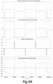
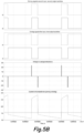
- Fig. 5A and Fig. 5B the switching frequency (200 kHz) waveforms are shown. They are the same waveforms for different line angles of 0 degrees and 90 degrees.
- the driving signals of the power switches 11-14 of the input half-bridge 4 and output bridge 5 show the phase shift ⁇ which produces the resulting voltage in the leakage inductance that drives the current injected to the transformer 40 from the input half-bridge 4 to the output half-bridge 5.
- Fig. 6 shows that the generic embodiment of Fig. 2 can be enhanced replacing any of the capacitive and/or switching legs 6-9 by a switched capacitor leg 10, according to an embodiment of the present invention.
- the power converter 1 comprises a three-phase architecture including a three-phase transformer 40 connected to a corresponding input switching leg 7 and output switching leg 9.
- a power converter 1 can be connected to each one of the three-phases of a three-phase AC input voltage source 2.
Landscapes
- Engineering & Computer Science (AREA)
- Power Engineering (AREA)
- Rectifiers (AREA)
- Dc-Dc Converters (AREA)
Priority Applications (5)
| Application Number | Priority Date | Filing Date | Title |
|---|---|---|---|
| EP23382841.7A EP4507182A1 (de) | 2023-08-11 | 2023-08-11 | Elektrischer wechselstrom-gleichstrom-schaltwandler |
| PCT/EP2024/072217 WO2025036765A1 (en) | 2023-08-11 | 2024-08-06 | An ac-dc switch mode electrical power converter |
| EP24754275.6A EP4670266B1 (de) | 2023-08-11 | 2024-08-06 | Elektrischer wechselstrom-gleichstrom-schaltwandler |
| KR1020267007336A KR20260052971A (ko) | 2023-08-11 | 2024-08-06 | Ac-dc 스위치 모드 전력 컨버터 |
| CN202480052584.9A CN121794885A (zh) | 2023-08-11 | 2024-08-06 | Ac-dc开关式电功率转换器 |
Applications Claiming Priority (1)
| Application Number | Priority Date | Filing Date | Title |
|---|---|---|---|
| EP23382841.7A EP4507182A1 (de) | 2023-08-11 | 2023-08-11 | Elektrischer wechselstrom-gleichstrom-schaltwandler |
Publications (1)
| Publication Number | Publication Date |
|---|---|
| EP4507182A1 true EP4507182A1 (de) | 2025-02-12 |
Family
ID=87848092
Family Applications (2)
| Application Number | Title | Priority Date | Filing Date |
|---|---|---|---|
| EP23382841.7A Withdrawn EP4507182A1 (de) | 2023-08-11 | 2023-08-11 | Elektrischer wechselstrom-gleichstrom-schaltwandler |
| EP24754275.6A Active EP4670266B1 (de) | 2023-08-11 | 2024-08-06 | Elektrischer wechselstrom-gleichstrom-schaltwandler |
Family Applications After (1)
| Application Number | Title | Priority Date | Filing Date |
|---|---|---|---|
| EP24754275.6A Active EP4670266B1 (de) | 2023-08-11 | 2024-08-06 | Elektrischer wechselstrom-gleichstrom-schaltwandler |
Country Status (4)
| Country | Link |
|---|---|
| EP (2) | EP4507182A1 (de) |
| KR (1) | KR20260052971A (de) |
| CN (1) | CN121794885A (de) |
| WO (1) | WO2025036765A1 (de) |
Citations (3)
| Publication number | Priority date | Publication date | Assignee | Title |
|---|---|---|---|---|
| US6239584B1 (en) * | 2000-06-20 | 2001-05-29 | Delta Electronics, Inc. | Two-inductor boost converter |
| CN201345618Y (zh) * | 2009-01-20 | 2009-11-11 | 华南理工大学 | 一种单级半桥ac-dc变换器 |
| US20180222333A1 (en) * | 2014-06-13 | 2018-08-09 | University Of Maryland | Integrated dual-output grid-to-vehicle (g2v) and vehicle-to-grid (v2g) onboard charger for plug-in electric vehicles |
Family Cites Families (1)
| Publication number | Priority date | Publication date | Assignee | Title |
|---|---|---|---|---|
| JP3907804B2 (ja) | 1997-10-06 | 2007-04-18 | 株式会社半導体エネルギー研究所 | 液晶表示装置 |
-
2023
- 2023-08-11 EP EP23382841.7A patent/EP4507182A1/de not_active Withdrawn
-
2024
- 2024-08-06 CN CN202480052584.9A patent/CN121794885A/zh active Pending
- 2024-08-06 WO PCT/EP2024/072217 patent/WO2025036765A1/en active Pending
- 2024-08-06 EP EP24754275.6A patent/EP4670266B1/de active Active
- 2024-08-06 KR KR1020267007336A patent/KR20260052971A/ko active Pending
Patent Citations (3)
| Publication number | Priority date | Publication date | Assignee | Title |
|---|---|---|---|---|
| US6239584B1 (en) * | 2000-06-20 | 2001-05-29 | Delta Electronics, Inc. | Two-inductor boost converter |
| CN201345618Y (zh) * | 2009-01-20 | 2009-11-11 | 华南理工大学 | 一种单级半桥ac-dc变换器 |
| US20180222333A1 (en) * | 2014-06-13 | 2018-08-09 | University Of Maryland | Integrated dual-output grid-to-vehicle (g2v) and vehicle-to-grid (v2g) onboard charger for plug-in electric vehicles |
Non-Patent Citations (3)
| Title |
|---|
| J.A. COBOS ET AL., DIRECT POWER CONVERTER -DPX- FOR HIGH GAIN AND HIGH CURRENT APPLICATIONS |
| RAMESH SRINIVASAN ET AL., A UNITY POWER FACTOR CONVERTER USING A HALF-BRIDGE TOPOLOGY |
| TUAN NGO ET AL., A SINGLE-PHASE BIDIRECTIONAL DUAL ACTIVE HALF-BRIDGE CONVERTER |
Also Published As
| Publication number | Publication date |
|---|---|
| EP4670266A1 (de) | 2025-12-31 |
| WO2025036765A1 (en) | 2025-02-20 |
| EP4670266B1 (de) | 2026-04-29 |
| CN121794885A (zh) | 2026-04-03 |
| KR20260052971A (ko) | 2026-04-20 |
Similar Documents
| Publication | Publication Date | Title |
|---|---|---|
| US8780585B2 (en) | Double phase-shifting full-bridge DC-to-DC converter | |
| US5894412A (en) | System with open-loop DC-DC converter stage | |
| US6310785B1 (en) | Zero voltage switching DC-DC converter | |
| CA2314782C (en) | Multi-mode power converters incorporating balancer circuits and methods of operation thereof | |
| US8693213B2 (en) | Resonant power factor correction converter | |
| US8842450B2 (en) | Power converter using multiple phase-shifting quasi-resonant converters | |
| US5245520A (en) | Asymmetrical duty cycle power converter | |
| US9847710B2 (en) | Universal system structure for low power adapters | |
| US20100259240A1 (en) | Bridgeless PFC converter | |
| AU2014361382B2 (en) | Improved high frequency series AC voltage regulator | |
| US20120032509A1 (en) | Voltage transforming device and method and power supply system | |
| EP2949035B1 (de) | Wechselstrom-wechselstrom-wandler | |
| KR20030011337A (ko) | 자율적 1차 인버터를 구비한 스위치 모드 전원장치 | |
| US11296607B2 (en) | DC-DC converter | |
| Soares et al. | High-efficiency interleaved totem-pole PFC converter with voltage follower characteristics | |
| KR102664416B1 (ko) | 브릿지리스 pfc 컨버터와 위상 천이 풀브릿지 dc-dc 컨버터가 통합된 ac-dc 컨버터 | |
| KR20190115364A (ko) | 단상 및 3상 겸용 충전기 | |
| US5883502A (en) | Power rectifier circuit | |
| JP2004215319A (ja) | 電源回路及び電子機器 | |
| EP4670266B1 (de) | Elektrischer wechselstrom-gleichstrom-schaltwandler | |
| US20210050794A1 (en) | A converter | |
| Belaguli et al. | High power factor operation of DCM series-parallel resonant converter | |
| Kalpana | High performance three-phase PFC rectifiers for telecom power supply | |
| US20240339940A1 (en) | Integrated auxiliary power supply with stable output at high-line and light-load conditions | |
| US12101023B2 (en) | Low power PFC converter |
Legal Events
| Date | Code | Title | Description |
|---|---|---|---|
| PUAI | Public reference made under article 153(3) epc to a published international application that has entered the european phase |
Free format text: ORIGINAL CODE: 0009012 |
|
| STAA | Information on the status of an ep patent application or granted ep patent |
Free format text: STATUS: THE APPLICATION HAS BEEN PUBLISHED |
|
| AK | Designated contracting states |
Kind code of ref document: A1 Designated state(s): AL AT BE BG CH CY CZ DE DK EE ES FI FR GB GR HR HU IE IS IT LI LT LU LV MC ME MK MT NL NO PL PT RO RS SE SI SK SM TR |
|
| STAA | Information on the status of an ep patent application or granted ep patent |
Free format text: STATUS: THE APPLICATION IS DEEMED TO BE WITHDRAWN |
|
| 18D | Application deemed to be withdrawn |
Effective date: 20250813 |