EP4507192A1 - Procédé et appareil de commande pour moteur électrique et dispositif électronique et support d'enregistrement - Google Patents
Procédé et appareil de commande pour moteur électrique et dispositif électronique et support d'enregistrement Download PDFInfo
- Publication number
- EP4507192A1 EP4507192A1 EP23790954.4A EP23790954A EP4507192A1 EP 4507192 A1 EP4507192 A1 EP 4507192A1 EP 23790954 A EP23790954 A EP 23790954A EP 4507192 A1 EP4507192 A1 EP 4507192A1
- Authority
- EP
- European Patent Office
- Prior art keywords
- motor
- faulty
- phase
- phases
- standby power
- Prior art date
- Legal status (The legal status is an assumption and is not a legal conclusion. Google has not performed a legal analysis and makes no representation as to the accuracy of the status listed.)
- Pending
Links
Images

Classifications
-
- H—ELECTRICITY
- H02—GENERATION; CONVERSION OR DISTRIBUTION OF ELECTRIC POWER
- H02P—CONTROL OR REGULATION OF ELECTRIC MOTORS, ELECTRIC GENERATORS OR DYNAMO-ELECTRIC CONVERTERS; CONTROLLING TRANSFORMERS, REACTORS OR CHOKE COILS
- H02P23/00—Arrangements or methods for the control of AC motors characterised by a control method other than vector control
- H02P23/14—Estimation or adaptation of motor parameters, e.g. rotor time constant, flux, speed, current or voltage
-
- H—ELECTRICITY
- H02—GENERATION; CONVERSION OR DISTRIBUTION OF ELECTRIC POWER
- H02P—CONTROL OR REGULATION OF ELECTRIC MOTORS, ELECTRIC GENERATORS OR DYNAMO-ELECTRIC CONVERTERS; CONTROLLING TRANSFORMERS, REACTORS OR CHOKE COILS
- H02P25/00—Arrangements or methods for the control of AC motors characterised by the kind of AC motor or by structural details
- H02P25/16—Arrangements or methods for the control of AC motors characterised by the kind of AC motor or by structural details characterised by the circuit arrangement or by the kind of wiring
- H02P25/22—Multiple windings; Windings for more than three phases
-
- H—ELECTRICITY
- H02—GENERATION; CONVERSION OR DISTRIBUTION OF ELECTRIC POWER
- H02P—CONTROL OR REGULATION OF ELECTRIC MOTORS, ELECTRIC GENERATORS OR DYNAMO-ELECTRIC CONVERTERS; CONTROLLING TRANSFORMERS, REACTORS OR CHOKE COILS
- H02P27/00—Arrangements or methods for the control of AC motors characterised by the kind of supply voltage
- H02P27/04—Arrangements or methods for the control of AC motors characterised by the kind of supply voltage using variable-frequency supply voltage, e.g. inverter or converter supply voltage
- H02P27/06—Arrangements or methods for the control of AC motors characterised by the kind of supply voltage using variable-frequency supply voltage, e.g. inverter or converter supply voltage using DC to AC converters or inverters
-
- H—ELECTRICITY
- H02—GENERATION; CONVERSION OR DISTRIBUTION OF ELECTRIC POWER
- H02P—CONTROL OR REGULATION OF ELECTRIC MOTORS, ELECTRIC GENERATORS OR DYNAMO-ELECTRIC CONVERTERS; CONTROLLING TRANSFORMERS, REACTORS OR CHOKE COILS
- H02P29/00—Arrangements for regulating or controlling electric motors, appropriate for both AC and DC motors
- H02P29/02—Providing protection against overload without automatic interruption of supply
- H02P29/024—Detecting a fault condition, e.g. short circuit, locked rotor, open circuit or loss of load
- H02P29/0243—Detecting a fault condition, e.g. short circuit, locked rotor, open circuit or loss of load the fault being a broken phase
-
- H—ELECTRICITY
- H02—GENERATION; CONVERSION OR DISTRIBUTION OF ELECTRIC POWER
- H02P—CONTROL OR REGULATION OF ELECTRIC MOTORS, ELECTRIC GENERATORS OR DYNAMO-ELECTRIC CONVERTERS; CONTROLLING TRANSFORMERS, REACTORS OR CHOKE COILS
- H02P29/00—Arrangements for regulating or controlling electric motors, appropriate for both AC and DC motors
- H02P29/02—Providing protection against overload without automatic interruption of supply
- H02P29/024—Detecting a fault condition, e.g. short circuit, locked rotor, open circuit or loss of load
- H02P29/027—Detecting a fault condition, e.g. short circuit, locked rotor, open circuit or loss of load the fault being an over-current
-
- H—ELECTRICITY
- H02—GENERATION; CONVERSION OR DISTRIBUTION OF ELECTRIC POWER
- H02P—CONTROL OR REGULATION OF ELECTRIC MOTORS, ELECTRIC GENERATORS OR DYNAMO-ELECTRIC CONVERTERS; CONTROLLING TRANSFORMERS, REACTORS OR CHOKE COILS
- H02P29/00—Arrangements for regulating or controlling electric motors, appropriate for both AC and DC motors
- H02P29/02—Providing protection against overload without automatic interruption of supply
- H02P29/024—Detecting a fault condition, e.g. short circuit, locked rotor, open circuit or loss of load
- H02P29/028—Detecting a fault condition, e.g. short circuit, locked rotor, open circuit or loss of load the motor continuing operation despite the fault condition, e.g. eliminating, compensating for or remedying the fault
-
- H—ELECTRICITY
- H02—GENERATION; CONVERSION OR DISTRIBUTION OF ELECTRIC POWER
- H02P—CONTROL OR REGULATION OF ELECTRIC MOTORS, ELECTRIC GENERATORS OR DYNAMO-ELECTRIC CONVERTERS; CONTROLLING TRANSFORMERS, REACTORS OR CHOKE COILS
- H02P29/00—Arrangements for regulating or controlling electric motors, appropriate for both AC and DC motors
- H02P29/60—Controlling or determining the temperature of the motor or of the drive
- H02P29/64—Controlling or determining the temperature of the winding
Definitions
- the present application belongs to the technical field of motor control, and in particular relates to a motor control method and apparatus, an electrical device, and a storage medium.
- electric vehicles, electric airplanes, and other electric devices usually have a power battery and a motor, where the power battery supplies power to the motor, and the motor converts electrical energy into mechanical energy to drive the electric device.
- fault-tolerant control of the motor is required to ensure that the electric device continues to operate.
- the current or torque of the motor is usually controlled by a fault-tolerant control algorithm after the motor is faulty.
- fault-tolerant control of a motor by controlling the current or torque, or the like, through a software algorithm is limited by computational errors of the algorithm, and it is difficult to realize precise fault-tolerant control.
- the present application proposes a motor control method and apparatus, an electrical device, and a storage medium.
- the present application provides a motor control method, where a neutral wire of a motor is connected to at least one standby power device, the method including:
- motor faulty phases are judged, and switching from primary power devices for the motor faulty phases to the standby power device is performed.
- the motor can continue to operate after it is faulty, and there is no safety risk due to the motor faulty phases during the operating process. Moreover, continued operation will not increase the degree of damage to the motor and will not shorten the life of the motor.
- the method further includes:
- a number of faulty phases is determined, and when the number of faulty phases is smaller than or equal to a number of the standby power devices, switching from the primary power devices for the motor faulty phases to the standby power device is performed.
- said determining motor faulty phases includes:
- the motor faulty phases are determined based on the motor sampling parameters, where the motor sampling parameters are operating parameters of the motor that are collected in real time in the operating process of the motor, which can accurately reflect the operating condition of the motor, so that the motor phases that are faulty can be accurately determined based on the motor sampling parameters, and the accuracy of determining the motor faulty phases in this way is very high.
- the motor sampling parameters include at least one of a phase current and a phase voltage of each phase of the motor, a temperature of each phase of winding, and a temperature of each primary power device connected to the motor.
- the motor sampling parameters include a phase current, a phase voltage and a winding temperature of each phase as well as a temperature of each primary power device, and so on. These parameters can accurately reflect the operating condition of the motor, and the motor faulty phases can be accurately determined based on these parameters after the motor is faulty.
- the motor sampling parameters include a phase current of each phase of the motor; and said determining motor faulty phases according to the motor sampling parameters includes: determining, if there is a phase current higher than a preset current threshold, a phase to which the phase current higher than the preset current threshold belongs as a motor faulty phase.
- the control module is pre-configured with a maximum value that the phase current can reach in the case where no short-circuit occurs, and based on a magnitude relationship between the phase currents and this maximum value, a motor faulty phase in which a short-circuit occurs can be accurately identified.
- the motor sampling parameters include a phase current of each phase of the motor; and said determining motor faulty phases according to the motor sampling parameters includes:
- a motor faulty phase in which a short-circuit occurs can also be accurately identified from the changes in the relative magnitudes of the phase currents of the phases.
- the motor sampling parameters include a phase voltage of each phase of the motor; and said determining motor faulty phases according to the motor sampling parameters includes: determining, if there is a phase voltage with voltage change abnormality, a phase corresponding to the phase voltage with voltage change abnormality as a motor faulty phase.
- the motor sampling parameters include a temperature of each phase of winding of the motor; and said determining motor faulty phases according to the motor sampling parameters includes: determining, if there is a temperature exceeding a first preset temperature interval, a phase corresponding to the temperature exceeding the first preset temperature interval as a motor faulty phase.
- the motor sampling parameters include a temperature of each primary power device connected to the motor; and said determining motor faulty phases according to the motor sampling parameters includes: determining, if there is a primary power device the temperature of which exceeds a second preset temperature interval, a phase corresponding to the primary power device the temperature of which exceeds the second preset temperature interval as a motor faulty phase.
- a faulty primary power device is determined from the changes in the temperatures of the primary power devices.
- the motor will also not work properly, and thus by identifying the faulty primary power device and subsequently performing switching from the faulty primary power device to a standby power device, damage to the motor by the faulty primary power device can be avoided.
- said controlling the motor faulty phases to switch from currently connected primary power devices to the standby power device includes:
- the motor faulty phases are turned off and standby power devices the number of which is the same as the number of faulty phases are controlled to be turned on, thereby replacing the primary power devices corresponding to the motor faulty phases with standby power devices.
- the motor can continue to operate after it is faulty, and there is no safety risk due to the motor faulty phase during the operating process. Moreover, continued operation will not increase the degree of damage to the motor and will not shorten the life of the motor.
- the method further includes:
- motor faulty phases that are faulty are all switched to standby power devices, so that the time in which the motor can continue to operate after the occurrence of a fault can be maximized.
- the method further includes:
- This embodiment enables timely switching to an unenabled standby power device in the event that an enabled standby power device is also faulty, thereby ensuring that the motor can continue to operate smoothly and thus avoiding damage to the motor by the faulty standby power device. If it is determined that the enabled standby power device is faulty and all standby power devices are enabled, the motor is controlled to shut down, thereby avoiding possible damage to the devices resulting from continued operation of the motor, and avoiding safety issues resulting from continued operation of the motor.
- the method before said controlling the motor faulty phases to switch from currently connected primary power devices to the standby power device, the method further includes: controlling the motor to shut down.
- the motor is first controlled to shut down, and then switching from the currently connected primary power devices for the motor faulty phases to standby power devices is performed, which enables preventing the motor from still operating in a faulty state before the switching is completed, and reduces the possibility of further damage to the motor.
- the current or voltage may change abruptly, and controlling the motor to stop before switching can effectively prevent the occurrence of damage to the motor resulting from the abrupt change in the current or voltage, thus improving the safety of the motor.
- the method further includes: controlling the motor to shut down when the number of faulty phases is larger than the number of the standby power devices.
- This embodiment avoids a higher degree of damage resulting from continued operation of the motor and avoids safety issues resulting from operation of the motor under a fault when the number of faulty phases is larger than the number of standby power devices.
- the number of phases of the motor is larger than or equal to 3; and the number of the standby power devices is larger than or equal to 1 and smaller than or equal to the number of phases of the motor minus 2.
- the number of standby power devices may be set to any value between 1 and the number of phases of the motor minus 2, and the larger the number of standby power devices provided within that range, the longer the motor can be kept operating by the fault-tolerant control of the present application after a fault.
- the present application provides a motor control apparatus, where a neutral wire of a motor is connected to at least one standby power device, the apparatus including:
- the present application provides a motor control device including a power supply module, a motor, an inversion module, a control module, and at least one standby power device, where
- the present application provides an electrical device including a memory, a processor, and a computer program stored on the memory and runnable on the processor, where the processor runs the computer program to implement a method as described in the first aspect.
- the present application provides a computer-readable storage medium having a computer program stored thereon, where the program is executed by a processor to implement a method as described in the first aspect.
- an embodiment means that a particular feature, structure, or characteristic described in connection with the embodiment can be included in at least one embodiment of the present application.
- the appearance of this phrase in various places in the specification does not necessarily refer to the same embodiment, nor is it a separate or alternative embodiment that is mutually exclusive with other embodiments. It is explicitly and implicitly understood by those skilled in the art that the embodiments described herein may be combined with other embodiments.
- a plurality of refers to two or more (including two).
- multiple groups refers to two or more groups (including two groups), and “multiple pieces” refers to two or more pieces (including two pieces).
- the technical terms “mounting”, “connection”, “connection” and “fixation” should be understood in a broad sense, for example, they can be fixed connection, detachable connection, or integration; or they can be mechanical connection or electrical connection; or they can be direct connection, indirect connection through an intermediate medium, or communication of the interiors of two elements or the relationship of interaction between two elements.
- mounting should be understood in a broad sense, for example, they can be fixed connection, detachable connection, or integration; or they can be mechanical connection or electrical connection; or they can be direct connection, indirect connection through an intermediate medium, or communication of the interiors of two elements or the relationship of interaction between two elements.
- Power batteries are increasingly more widely used.
- Power batteries are not only applied in energy storage power source systems such as water, fire, wind and solar power stations, but also widely applied in electric transport tools, such as electric bicycles, electric motorcycles, and electric vehicles, as well as many fields, such as military equipment and aerospace.
- electric transport tools such as electric bicycles, electric motorcycles, and electric vehicles
- military equipment and aerospace power is usually provided by means of power batteries, specifically by means of an electric motor converting the electrical energy of the power battery into mechanical energy so as to drive the operation of the electrical device.
- faults may occur during the operating process of the motor.
- a short-circuit or broken-circuit fault occurs in one or more phases of windings of the motor, or a short-circuit or broken-circuit fault occurs in one or more power devices in the motor inverter, and so forth.
- a motor When a motor is faulty, it may cause the motor to shut down directly, and even if the motor can still run, continuing to run in a faulty state will increase the degree of damage to the motor and shorten the life of the motor, and continuing to run in a faulty state will also bring a great safety risk to the user. Therefore, it is necessary to take certain measures to deal with the fault when the motor is faulty.
- the inventors improve the structure of the circuit in which the motor is located in the existing electrical device and leads-out a neutral wire from the neutral point where all the windings of the motor are connected, through which neutral wire at least one standby power device is connected.
- the present application calls each power device in the motor inverter as a primary power device.
- Each standby power device performs the same function as each primary power device in the motor inverter.
- Each standby power device is connected in parallel with the power battery as well as each primary power device in the motor inverter.
- the inventors have designed a motor control method, which determines motor faulty phases if it is detected in an operating process of the motor that the motor is faulty; and controls the motor faulty phases to switch from currently connected primary power devices to the standby power device.
- the primary power devices connected to the motor faulty phases are turned off and the standby power devices are controlled to be turned on, thereby replacing the primary power devices corresponding to the motor faulty phases with standby power devices.
- the motor can continue to operate after it is faulty, and there is no safety risk due to the motor faulty phase during the operating process. Moreover, continued operation will not increase the degree of damage to the motor and will not shorten the life of the motor.
- the motor control method disclosed in embodiments of the present application may be used for, but is not limited to, fault-tolerant control of three-phase motors, four-phase motors, five-phase motors, six-phase motors, or other more-phase motors.
- the motor control method provided in embodiments of the present application can be applied to, but are not limited to, electric toys, electric tools, battery vehicles, electric cars, ships, spacecraft, and the like, provided with power batteries and motors.
- the electric toy may include a stationary or mobile electric toy, for example, a game console, an electric car toy, an electric ship toy, and an electric aircraft toy, and the like
- the spacecraft may include an aircraft, a rocket, a space shuttle and a spaceship, and the like.
- circuit structure in which the motor is located in these electrical apparatuses can be improved as described above, and the motor control method disclosed in embodiments of the present application can be applied to perform fault-tolerant control of the motor. In this way, in the event of a fault of the motor, it is possible to continue safe operation of the motor by switching to standby power devices without hindering the normal use of the electrical apparatus or increasing the degree of damage to the motor.
- Embodiments of the present application provide a motor control device. As shown in FIG. 1 , the device includes: a power supply module 1, a motor 2, an inversion module 3, a control module 4, and at least one standby power device 5.
- the power supply module 1, the inversion module 3, and each standby power device 5 are connected in parallel.
- the windings of the motor 2 are connected in one-to-one correspondence with primary power devices 6 in the inversion module 3.
- the at least one standby power device 5 is all connected to a neutral wire of the motor 2.
- the control module 4 is connected to the motor 2, the inversion module 3, and each standby power device 5.
- the control module 4 is used for determining motor faulty phases and a number of faulty phases if it is detected in an operating process of the motor 2 that the motor 2 is faulty; and controlling the motor faulty phases to switch from currently connected primary power devices 6 to the standby power device 5 when the number of faulty phases is smaller than or equal to a number of the standby power devices 5.
- the above power supply module 1 can be a power battery, and the power battery can be a ternary power battery, a lithium iron phosphate battery, a lithium titanate battery, a lead-acid storage battery, and so on.
- the inversion module 3 is an inverter corresponding to the motor 2, and the number of windings of the motor 2 is equal to the number of the primary power devices 6 in the inversion module 3.
- the motor 2 may be a three-phase motor, a four-phase motor, or a six-phase motor, or the like.
- the neutral wire of the motor 2 is the wire leading out from the connection point where all windings of the motor 2 are connected.
- the control module 4 may include a motor control unit (MCU) and/or a vehicle control unit (VCU), or, alternatively, the control module 4 may be a domain control unit.
- MCU motor control unit
- VCU vehicle control unit
- the structure and the specifications of the standby power device 5 may be the same as the structure and the specifications of the primary power device 6 in the inversion module 3. Both the standby power device 5 and the primary power device 6 may be realized using bridge arm switches of insulated gate bipolar transistors (IGBTs).
- IGBTs insulated gate bipolar transistors
- the standby power device 5 may include two power transistors connected in series, the power transistors including a switch transistor and a flyback diode connected in parallel.
- the standby power device 5 may also include two switches connected in series, both of which may be switch transistors or relay switches.
- the motor 2 can continue to operate after a number of motor phases that is less than a certain number of phases are faulty, where the certain number of phases can be at most the total number of phases of the motor 2 minus 2.
- the total number of phases of the motor 2 is larger than or equal to 3. For example, for a three-phase motor, operation can continue if one phase is faulty. For a four-phase motor, operation can continue if one or two phases are faulty. For a six-phase motor, operation can continue if one phase, two phases, three phases, or four phases are faulty.
- At least one standby power device 5 is connected to the neutral wire of the motor 2, where the number of the standby power devices 5 may be any value between 1 and the total number of phases of the motor 2 minus 2.
- the number of the standby power devices 5 may be any value between 1 and the total number of phases of the motor 2 minus 2.
- one standby power device 5 may be connected to the neutral wire of the three-phase motor.
- one or two standby power devices 5 may be connected to the neutral wire of the four-phase motor.
- one, two, three or four standby power devices 5 may be connected to the neutral wire of the six-phase motor.
- FIG. 2 illustrates a schematic diagram of a circuit in which one standby power device 5 is provided in a three-phase motor.
- the standby power device 5 and three primary power devices in the inversion module 3 are each realized by using a bridge arm consisting of two power transistors connected in series.
- the motor faulty phases are controlled to switch from the connected primary power devices 6 to the standby power device 5, thereby replacing the primary power devices 6 corresponding to the motor faulty phases with the standby power device 5, so that the motor 2 can continue to operate after it is faulty, and there is no safety risk due to the motor faulty phase during the operating process, thereby ensuring that the motor control device can be operated in a safe and stable manner. Moreover, continued operation will not increase the degree of damage to the motor 2 and will not shorten the life of the motor 2.
- Some other embodiments of the present application provide a motor control method, which is applied to the motor control device proposed in the above embodiments.
- a neutral wire of a motor is connected to at least one standby power device.
- the number of phases of the motor is larger than or equal to 3, and the number of the standby power devices is larger than or equal to 1 and smaller than or equal to the number of phases of the motor minus 2.
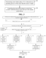
- FIG. 3 illustrates a flowchart of a motor control method.
- the method specifically includes the following steps: Step 101: determining motor faulty phases if it is detected in an operating process of the motor that the motor is faulty.
- each phase of winding of the motor as well as each primary power device in the motor inverter may be provided with collection means for collecting motor sampling parameters, where the motor sampling parameters include at least one of a phase current and a phase voltage of each phase of the motor, a temperature of each phase of winding, or a temperature of each primary power device, and other data.
- the collection means includes a temperature sensor, a current sensor, a voltage sensor, and the like.
- a temperature sensor, a current sensor or a voltage sensor may be mounted at each phase of winding of the motor, and a temperature sensor, a current sensor or a voltage sensor may be mounted at each power transistor in each primary power device.
- the collection of the phase current and the phase voltage can also be performed by a current sampling circuit for collecting the current and a voltage sampling circuit for collecting the voltage, respectively.
- the motor sampling parameters are collected in real time during the operating process of the motor, and based on the motor sampling parameters, it can be determined whether the motor is faulty or not.
- control module judges whether the temperatures of the windings of the phases among the motor sampling parameters are higher than a first preset temperature interval threshold, and determines that the motor is faulty if there exists a winding with a temperature higher than the first preset temperature interval threshold.
- the control module judges whether the temperatures corresponding to the primary power devices among the motor sampling parameters are higher than a second preset temperature interval threshold, and determines that the motor is faulty if there exists a primary power device with a temperature higher than the second preset temperature interval threshold.
- the control module judges whether the fluctuations of the phase currents of the phases among the motor sampling parameters are abnormal.
- the control module may be pre-configured with fluctuation data for the phase currents of the phases in the normal operating state of the motor without faults, where the fluctuation data may be a table of mapping relationships between phase currents and time, or a current curve of the phase currents over time, or the like.
- the control module compares the phase currents of the phases that are collected in real time with the preset fluctuation data of the phase currents of the phases, respectively, and if it is determined that there exists a phase current with a fluctuation situation that is inconsistent with the preset fluctuation data, it is determined that there is a fault in the motor.
- the control module judges whether the fluctuations of the phase voltages of the phases among the motor sampling parameters are abnormal.
- the control module may be pre-configured with fluctuation data for the phase voltages of the phases in the normal operating state of the motor without faults, where the fluctuation data may be a table of mapping relationships between phase voltages and time, or a voltage curve of the phase voltages over time, or the like.
- the control module compares the phase voltages of the phases that are collected in real time with the preset fluctuation data of the phase voltages of the phases, respectively, and if it is determined that there exists a phase voltage with a fluctuation situation that is inconsistent with the preset fluctuation data, it is determined that there is a fault in the motor.
- control module determines that the motor is faulty by one or more of the above ways of judging whether the motor is faulty, it further determines motor faulty phases that are faulty.
- the control module determines motor faulty phases according to the motor sampling parameters.
- the motor faulty phases are determined based on the motor sampling parameters, where the motor sampling parameters are operating parameters of the motor that are collected in real time in the operating process of the motor, which can accurately reflect the operating condition of the motor, so that the motor phases that are faulty can be accurately determined based on the motor sampling parameters, and the accuracy of determining the motor faulty phases in this way is very high.
- the motor sampling parameters include a phase current of each phase of the motor. Due to the occurrence of a short-circuit in a phase, the impedance of that short-circuited phase decreases and approaches 0, and thus the phase current of that short-circuited phase will be very high.
- the control module judges whether the phase current of each phase is higher than a preset current threshold, which may be the maximum value of the phase current that can be achieved without a short-circuit. If it is determined that there is a phase current higher than the preset current threshold, a phase to which the phase current higher than the preset current threshold belongs is determined as a motor faulty phase. The motor faulty phase that is short-circuited can be accurately identified based on the changes in the phase currents.
- the motor sampling parameters include a phase current of each phase of the motor.
- the control module separately calculates a difference absolute value between phase currents of any two phases. It judges whether each difference absolute value calculated is larger than a preset difference threshold, and if it is determined that there is a difference absolute value larger than the preset difference threshold, a phase with the highest phase current out of two phases corresponding to the difference absolute value larger than the preset difference threshold is determined as a motor faulty phase.
- the motor faulty phase in which a short-circuit occurs can be accurately identified based on the changes in the relative magnitudes of the phase currents.
- the control module detects that the phase current of a phase is lower than a certain threshold, while the other phase currents become high, where that certain threshold can be a value close to 0, the phase corresponding to the phase current lower than the certain threshold is determined as a motor faulty phase.
- the motor faulty phase in which a broken-circuit occurs can be accurately identified based on the changes in the current currents of the phases.
- the control module determines that the phase current of a certain phase of winding becomes higher by detecting the changes in the magnitudes of the phase current flowing through the winding, then that phase can be determined as a motor faulty phase. Based on the changes in the magnitudes of the phase currents flowing through the windings, a motor faulty phase with a winding inter-turn short-circuits can be accurately identified.
- the motor sampling parameters include a phase voltage of each phase of the motor.
- the resistance of the short-circuited phase tends to approach zero, which is equivalent to a wire, and at this time, the phase voltage corresponding to the short-circuited phase becomes very low and the phase voltage tends to approach zero, whereas if a broken-circuit occurs in a phase of the motor, the resistance of the broken-circuited phase is very large and there is almost no current passing through the broken-circuited phase, and at this time, the voltage of the broken-circuited phase becomes very high
- the control module monitor in real time whether there is voltage change abnormality in the phase voltage of each phase, and if it detects that the phase voltage of a phase suddenly becomes low, or the phase voltage of a phase suddenly becomes high, the phase corresponding to the phase voltage that has changed abnormally will be determined as a motor faulty phase.
- a motor faulty phase in which a short-circuit tends to approach zero, which is equivalent to a wire, and at this time, the phase voltage
- the motor sampling parameters include a temperature of each phase of winding of the motor.
- the temperature of the inter-turn short-circuited winding gradually increases over time. Therefore, the temperature of the winding can be detected by a temperature sensor provided on the winding, and the motor faulty phase can be identified based on the changes in winding temperatures.
- the control module is pre-configured with a first preset temperature interval, where an upper limit value of the first preset temperature interval may be the maximum temperature that can be reached by the windings during normal operation, and a lower limit value may be an average temperature of the phases of windings when the phases of windings operate normally.
- the control module judges whether the temperature of each phase of winding exceeds the first preset temperature interval, and if it is determined that there is a temperature exceeding the first preset temperature interval, a phase corresponding to the temperature exceeding the first preset temperature interval is determined as a motor faulty phase.
- the inverter of the motor includes a plurality of primary power devices, and each phase of winding of the motor is connected in one-to-one correspondence with the primary power devices of the inverter.
- the motor also cannot operate normally, so real-time monitoring of each primary power device is also required.
- a temperature sensor can be provided at each primary power device to collect the temperature of each primary power device. The motor sampling parameters thus include the temperature of each primary power device.
- the control module is pre-configured with a second preset temperature interval, where an upper limit value of the second preset temperature interval may be the maximum temperature that may be reached by the primary power devices during normal operation, and a lower limit value may be the average temperature of the primary power devices during normal operation or the lowest temperature during normal operation.
- the control module judges whether the temperature of each primary power device exceeds the second preset temperature interval. If it is determined that there is a primary power device the temperature of which exceeds the second preset temperature interval, a phase corresponding to the primary power device exceeding the second preset temperature interval is determined as a motor faulty phase.
- the primary power device in which the fault occurs can be accurately identified, and thus the corresponding motor faulty phase can be determined.
- the motor faulty phase can also be determined by other means based on the motor sampling parameters, as long as the motor faulty phase can be determined, and the embodiments of the present application do not impose any special limitations on the specific means of determining the motor faulty phase.
- control module monitors whether the motor is faulty in real time based on the motor sampling parameters, and determines specific motor faulty phases based on the motor sampling parameters after determining that the motor is faulty.
- Step 102 controlling the motor faulty phases to switch from currently connected primary power devices to the standby power device.
- control module After obtaining the specific motor faulty phases by means of step 101, the control module switches from the currently connected primary power devices for the motor faulty phases to the standby power device.
- the currently connected primary power devices for the motor faulty phases are controlled to be turned off.
- Standby power devices in the at least one standby power device are controlled to be turned on.
- the number of the standby power devices that are turned on may be equal to the number of the primary power devices corresponding to the motor faulty phases.
- a three-phase motor as shown in FIG. 2 , if one motor faulty phase is detected, for example, if the winding LA or a primary power device connected to the winding LA is detected to be faulty, where the fault of the primary power device connected to the winding LA may be a fault of the switch transistor V1 or V4 or the flyback diode D1 or D4, the switch transistors V1 and V4 may be controlled to be turned off, and the standby power device 5 may be enabled by controlling the switch transistor V7 to be turned on, or controlling the switch transistor V8 to be turned on.
- the motor faulty phases are turned off and the standby power devices are controlled to be turned on, thereby replacing the primary power devices corresponding to the motor faulty phases with standby power devices.
- the motor can continue to operate after it is faulty, and there is no safety risk due to the motor faulty phases during the operating process. Moreover, continued operation will not increase the degree of damage to the motor and will not shorten the life of the motor.
- step 101 after each specific motor faulty phase is determined by step 101, the number of motor faulty phases is also counted to obtain the number of faulty phases.
- the control module judges whether the number of faulty phases is smaller than or equal to the number of standby power devices provided in the current circuit structure. If it is determined that the number of faulty phases is smaller than or equal to the number of standby power devices, the operation of step 102 is performed to turn off the primary power device connected to the motor faulty phase, and to control standby power devices the number of which is the same as the number of faulty phases to be turned on.
- a number of faulty phases is determined, and when the number of faulty phases is smaller than or equal to a number of the standby power devices, switching from the primary power devices for the motor faulty phases to standby power devices the number of which is the same as the number of faulty phases is performed.
- the process of switching the motor faulty phases from the currently connected primary power devices to the standby power devices can be implemented in a variety of ways.
- the currently connected primary power devices for the motor faulty phases may be turned off first, and then standby power devices the number of which is the same as the number of faulty phases may be controlled to be turned on.
- standby power devices the number of which is the same as the number of faulty phases may be controlled to be turned on first, and then the currently connected primary power devices for the motor faulty phases may be turned off.
- the motor may be controlled to shut down first, then the currently connected primary power devices for the motor faulty phases may be turned off, and finally standby power devices the number of which is the same as the number of faulty phases may be controlled to be turned on.
- the motor may be controlled to shut down first, then standby power devices the number of which is the same as the number of faulty phases may be controlled to be turned on, and finally the currently connected primary power devices for the motor faulty phases may be turned off.
- the motor is first controlled to shut down, and then switching from the currently connected primary power devices for the motor faulty phases to standby power devices is performed, which enables preventing the motor from still operating in a faulty state before the switching is completed, and reduces the possibility of further damage to the motor.
- the current or voltage may change abruptly, and controlling the motor to stop before switching can effectively prevent the occurrence of damage to the motor resulting from the abrupt change in the current or voltage, thus improving the safety of the motor.
- the motor sampling parameters of the remaining motor phases are still collected in real time, and these motor phases are monitored as to whether they are faulty based on the collected motor sampling parameters.
- the above preset number is the minimum number of motor phases allowed for the motor to operate.
- the new motor faulty phases are determined and the number of new faulty phases is counted. If the number of new faulty phases is smaller than or equal to the number of currently unenabled standby power devices, switching from primary power devices connected to the new motor faulty phases to unenabled standby power devices the number of which is the same as the number of new faulty phases is performed. If the number of new faulty phases is larger than the number of currently unenabled standby power devices, the motor is controlled to shut down.
- motor faulty phases that are faulty are all switched to standby power devices, so that the time in which the motor can continue to operate after the occurrence of a fault can be lengthened to the greatest extent.
- operating parameters of enabled standby power devices may also be collected, where the operating parameters may include, for example, temperatures, currents, or voltages of the enabled standby power devices.
- the faulty standby power device is turned off and the unenabled standby power device is controlled to be turned on, which enables timely switching to an unenabled standby power device in the event that an enabled standby power device is also faulty, thereby ensuring that the motor can continue to operate smoothly and thus avoiding damage to the motor by the faulty standby power device.
- the motor is controlled to shut down, thereby avoiding possible damage to the devices resulting from continued operation of the motor, and avoiding safety issues resulting from continued operation of the motor.
- control module after determining the number of faulty phases, judges that the number of faulty phases is larger than the number of standby power devices provided in the current circuit, it is not possible to replace the primary power devices for all motor faulty phases even if all standby power devices in the current circuit are enabled; therefore, the motor is controlled to shut down, so as to avoid a higher degree of damage resulting from the continued operation of the motor and to avoid safety issues resulting from operation of the motor under the fault.
- the control module after judging that the number of faulty phases is larger than the number of standby power devices, may also send a prompt message to the user, which is used to prompt the user that the motor is faulty and needs to be repaired before being used.
- the control module may send the prompt message to a terminal of the user, such as a cell phone or a computer.
- the control module may display this prompt message on a display of the electrical device in which the motor is located. For example, if the electrical device is an electric car, the prompt message may be displayed in the car central control screen of the electric car.
- S1 collecting motor sampling parameters such as motor phase and line voltages and currents, winding temperatures, and temperatures of primary power devices.
- S2 judging whether the motor or the motor inverter is faulty, and if not, continuing with step S2; and if yes, performing step S3.
- S3 determining motor faulty phases and a number of faulty phases.
- S4 judging whether the number of faulty phases is smaller than or equal to the number of standby power devices, and if not, performing step S5; and if yes, performing any of steps S6, S6', S8 or S8'.
- S5 controlling the motor to shut down.
- S6 turning off primary power devices connected to the motor faulty phases, and then performing step S7.
- S6' controlling the motor to stop, then turning off the primary power devices connected to the motor faulty phases, and then performing step S7.
- S7 controlling standby power devices the number of which is the same as the number of faulty phases to be turned on, and then performing step S10.
- S8 controlling standby power devices the number of which is the same as the number of faulty phases to be turned on, and then performing step S9.
- S8' controlling the motor to stop, controlling standby power devices the number of which is the same as the number of faulty phases to be turned on, and then performing step S9.
- S9 turning off primary power devices connected to the motor faulty phases, and then performing step S10.
- S10 the motor enters the fault-tolerant control mode.
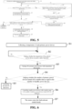
- FIG. 5 illustrates a schematic flowchart of fault-tolerant control when the motor is short-circuited or broken-circuited.
- A1 collecting motor sampling parameters such as motor phase and line voltages, stator winding temperatures, and so on.
- A2 judging whether the phase current exceeds a current safety threshold, if yes, performing step A3, and if not, performing step A4.
- A3 turning off primary power devices connected to the motor faulty phases with current abnormality and performing step A7.
- A4 judging whether the difference between the temperature of any phase of winding and a preset average temperature is smaller than a first temperature threshold, if not, returning to step A2, and if yes, performing step A5.
- A5 judging whether the temperature of each primary power device in the motor inverter exceeds a second temperature threshold, if not, returning to step A2, and if yes, performing step A6.
- A6 turning off a primary power device with temperature abnormality.
- A7 judging whether the number of primary power devices turned off is smaller than or equal to the number of standby power devices, if yes, performing step A8, and if not, performing step A10.
- A8 controlling standby power devices with a number equal to the number of primary power devices turned off.
- A9 the motor enters the fault-tolerant control mode.
- A10 controlling the motor to shut down.
- FIG. 6 illustrates a schematic flowchart of fault-tolerant control in the event of a fault in a primary power device in a motor inverter.
- B1 collecting a temperature of each primary power device.
- B2 judging whether the temperature of the primary power device exceeds a safety threshold, if not, continuing to perform step B2, and if yes, performing step B3.
- B3 turning off a primary power device with temperature abnormality.
- B4 judging whether the number of primary power devices turned off is smaller than or equal to the number of standby power devices, if not, performing step B5, and if yes, performing step B6.
- B5 controlling the motor to shut down.
- B6 controlling standby power devices with a number equal to the number of primary power devices turned off to be turned on.
- B7 the motor enters the fault-tolerant control mode.
- the fault-tolerant control mode in FIGS. 4-6 as described above is an operating mode of switching to standby power devices to continue operation after a motor faulty phase has occurred.
- motor faulty phases and the number of faulty phases are judged, and when the number of faulty phases is smaller than or equal to the number of standby power devices, primary power devices for the motor faulty phases are turned off, and standby power devices the number of which is the same as the number of faulty phases are controlled to be turned on.
- the motor can continue to operate after it is faulty, and there is no safety risk due to the motor faulty phases during the operating process. Moreover, continued operation will not increase the degree of damage to the motor and will not shorten the life of the motor.
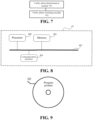
- Some other embodiments of the present application provide a motor control apparatus for performing the motor control method provided in any of the above embodiments, with reference to FIG. 7 , the apparatus including:
- the faulty phase switching module 702 is further used for determining a number of faulty phases of the motor; and performing, when the number of faulty phases is smaller than or equal to a number of the standby power devices, the operation of controlling the motor faulty phases to switch from currently connected primary power devices to the standby power devices.
- the faulty phase determination module 701 is used for acquiring motor sampling parameters for the operating process of the motor; and determining motor faulty phases according to the motor sampling parameters.
- the motor sampling parameters include at least one of a phase current and a phase voltage of each phase of the motor, a temperature of each phase of winding, and a temperature of each primary power device connected to the motor.
- the motor sampling parameters include a phase current of each phase of the motor; and the faulty phase determination module 701 is used for determining, if there is a phase current higher than a preset current threshold, a phase to which the phase current higher than the preset current threshold belongs as a motor faulty phase.
- the motor sampling parameters include a phase current of each phase of the motor; and the faulty phase determination module 701 is used for separately calculating a difference absolute value between phase currents of any two phases; and determining, if there is a difference absolute value larger than a preset difference threshold, a phase with the highest phase current out of two phases corresponding to the difference absolute value larger than the preset difference threshold as a motor faulty phase.
- the motor sampling parameters include a phase voltage of each phase of the motor; and the faulty phase determination module 701 is used for determining, if there is a phase voltage with voltage change abnormality, a phase corresponding to the phase voltage with change abnormality as a motor faulty phase.
- the motor sampling parameters include a temperature of each phase of winding of the motor; and the faulty phase determination module 701 is used for determining, if there is a temperature exceeding a first preset temperature interval, a phase corresponding to the temperature exceeding the first preset temperature interval as a motor faulty phase.
- the motor sampling parameters include a temperature of each primary power device connected to the motor; and the faulty phase determination module 701 is used for determining, if there is a primary power device the temperature of which exceeds a second preset temperature interval, a phase corresponding to the primary power device the temperature of which exceeds the second preset temperature interval as a motor faulty phase.
- the faulty phase switching module 702 is used for controlling the currently connected primary power devices for the motor faulty phases to be turned off; and controlling standby power devices the number of which is the same as the number of faulty phases out of the at least one standby power device to be turned on.
- the faulty phase determination module 701 is further used for continuing, if the number of remaining motor phases other than the motor faulty phase is larger than a preset number and there are unenabled standby power devices in the at least one standby power device, to detect whether new motor faulty phases appear in the remaining motor phases; and the faulty phase switching module 702 is further used for switching, if the number of the new motor faulty phases is smaller than or equal to the number of the unenabled standby power devices, from primary power devices connected to the new motor faulty phases to the unenabled standby power devices.
- the apparatus further includes: a standby power device monitoring module for collecting operating parameters of an enabled standby power device and determining whether the enabled standby power device is faulty according to the operating parameters; if it is determined that the enabled standby power device is faulty and there is currently an unenabled standby power device, turning off the faulty standby power device and controlling the unenabled standby power device to be turned on; and controlling the motor to shut down if it is determined that the enabled standby power device is faulty and all standby power devices are enabled.
- a standby power device monitoring module for collecting operating parameters of an enabled standby power device and determining whether the enabled standby power device is faulty according to the operating parameters; if it is determined that the enabled standby power device is faulty and there is currently an unenabled standby power device, turning off the faulty standby power device and controlling the unenabled standby power device to be turned on; and controlling the motor to shut down if it is determined that the enabled standby power device is faulty and all standby power devices are enabled.
- the faulty phase switching module 702 is further used for controlling the motor to shut down before controlling the motor faulty phases to switch from currently connected primary power devices to the standby power device.
- the faulty phase switching module 702 is further used for controlling the motor to shut down when the number of faulty phases is larger than the number of standby power devices.
- the number of phases of the motor is larger than or equal to 3; and the number of the standby power devices is larger than or equal to 1 and smaller than or equal to the number of phases of the motor minus 2.
- the motor control apparatus provided in the above embodiments of the present application is motivated by the same inventive concept as the motor control method provided in the embodiments of the present application, and has the same beneficial effect as the method employed, operated, or realized by the application stored therein.
- An implementation of the present application further provides an electrical device to perform the motor control method described above.
- the electrical device may be an electric vehicle, an electric toy, a ship, a spacecraft, or the like that is provided with a power battery, a motor, and a motor inverter.
- FIG. 8 it illustrates a schematic diagram of an electrical device provided in some embodiments of the present application. As shown in FIG.
- an electrical device 40 includes: a processor 400, a memory 401, a bus 402, and a communication interface 403, where the processor 400, the communication interface 403, and the memory 401 are connected via the bus 402; and the memory 401 stores a computer program that is runnable on the processor 400, and the processor 400, when running the computer program, executes the motor control method provided in any one of the preceding implementations of the present application.
- the memory 401 may include a high-speed random access memory (RAM), and may also include a non-volatile memory, such as at least one disk memory.
- RAM random access memory
- non-volatile memory such as at least one disk memory.
- the communication connection between this apparatus network element and at least one other network element is implemented through at least one communication interface 403 (which may be wired or wireless), which may use the Internet, a wide area network, a local network, a metropolitan area network, and the like.
- the bus 402 may be an ISA bus, a PCI bus, or an EISA bus, and so on. Buses may be classified as address buses, data buses, control buses, and so on. Among them, the memory 401 is used to store a program, and the processor 400 executes the program after receiving an execution instruction, and the motor control method disclosed in any one of the foregoing implementations of embodiments of the present application may be applied in the processor 400, or implemented by the processor 400.
- the processor 400 may be an integrated circuit chip with processing capabilities for signals. During implementation, the steps of the method described above may be accomplished by integrated logic circuitry in hardware in processor 400 or by instructions in the form of software.
- the processor 400 described above may be a general purpose processor, which includes a central processing unit (CPU), a network processor (NP), and the like; and it may also be a digital signal processor (DSP), an application specific integrated circuit (ASIC), a field programmable gate array (FPGA ) or other programmable logic devices, discrete gates or transistor logic devices, or discrete hardware components.
- DSP digital signal processor
- ASIC application specific integrated circuit
- FPGA field programmable gate array
- the methods, steps, and logical block diagrams as disclosed in embodiments of the present application can be implemented or performed.
- the general purpose processor may be a microprocessor, or the processor may also be any conventional processor, etc.
- the steps of the method disclosed in conjunction with the embodiments of the present application can be directly embodied as being performed by the hardware decoding processor or being performed with a combination of hardware and software modules in the decoding processor.
- the software module may be located in a random access memory, a flash memory, a read-only memory, a programmable read-only memory or an electrically rewritable programmable memory, a register, and other storage media well established in the art.
- the storage medium is located in the memory 401, and the processor 400 reads the information in the memory 401 and completes the steps of the above method in combination with its hardware.
- the electrical device provided in embodiments of the present application is motivated by the same inventive concept as the motor control method provided in embodiments of the present application, and has the same beneficial effect as the method it employs, runs or implements.
- An implementation of the present application further provides a computer-readable storage medium corresponding to the motor control method provided in the preceding implementations.
- the computer-readable storage medium illustrated therein is an optical disk 30 on which a computer program (i.e., a program product) is stored, where the computer program, when run by a processor, executes the motor control method provided in any of the preceding implementations.
- examples of the computer-readable storage medium may also include, but not limited to, a phase-change random access memory (PRAM), a static random access memory (SRAM), a dynamic random access memory (DRAM) and other types of random access memory (RAM), a read-only memory (ROM), an electrically erasable programmable read-only memory (EEPROM), a flash memory, or other optical, magnetic storage media, which will not be repeated herein.
- PRAM phase-change random access memory
- SRAM static random access memory
- DRAM dynamic random access memory
- RAM random access memory
- ROM read-only memory
- EEPROM electrically erasable programmable read-only memory
- flash memory or other optical, magnetic storage media, which will not be repeated herein.
- the computer-readable storage medium provided in the above embodiments of the present application is motivated by the same inventive concept as the motor control method provided in the embodiments of the present application, and has the same beneficial effect as the method employed, run or implemented by the application program stored therein.
Landscapes
- Engineering & Computer Science (AREA)
- Power Engineering (AREA)
- Control Of Ac Motors In General (AREA)
- Control Of Electric Motors In General (AREA)
Applications Claiming Priority (2)
| Application Number | Priority Date | Filing Date | Title |
|---|---|---|---|
| CN202210429619.9A CN115378343B (zh) | 2022-04-22 | 2022-04-22 | 电机控制方法、装置、用电设备及存储介质 |
| PCT/CN2023/082224 WO2023202293A1 (fr) | 2022-04-22 | 2023-03-17 | Procédé et appareil de commande pour moteur électrique et dispositif électronique et support d'enregistrement |
Publications (2)
| Publication Number | Publication Date |
|---|---|
| EP4507192A1 true EP4507192A1 (fr) | 2025-02-12 |
| EP4507192A4 EP4507192A4 (fr) | 2025-07-30 |
Family
ID=84060135
Family Applications (1)
| Application Number | Title | Priority Date | Filing Date |
|---|---|---|---|
| EP23790954.4A Pending EP4507192A4 (fr) | 2022-04-22 | 2023-03-17 | Procédé et appareil de commande pour moteur électrique et dispositif électronique et support d'enregistrement |
Country Status (4)
| Country | Link |
|---|---|
| US (1) | US20250023501A1 (fr) |
| EP (1) | EP4507192A4 (fr) |
| CN (1) | CN115378343B (fr) |
| WO (1) | WO2023202293A1 (fr) |
Families Citing this family (1)
| Publication number | Priority date | Publication date | Assignee | Title |
|---|---|---|---|---|
| CN115378343B (zh) * | 2022-04-22 | 2024-05-03 | 宁德时代新能源科技股份有限公司 | 电机控制方法、装置、用电设备及存储介质 |
Family Cites Families (14)
| Publication number | Priority date | Publication date | Assignee | Title |
|---|---|---|---|---|
| FR2954618B1 (fr) * | 2009-12-22 | 2012-12-28 | Astrium Sas | Onduleur reconfigurable, a tolerance de pannes, pour l'alimentation d'un moteur triphase synchrone a aimants permanents, et ensemble desdits onduleur et moteur |
| CN102687389B (zh) * | 2010-01-25 | 2015-04-29 | 丰田自动车株式会社 | 马达驱动系统、马达驱动系统的控制方法、以及行驶装置 |
| EP3113355B1 (fr) * | 2014-02-28 | 2019-05-22 | NSK Ltd. | Dispositif de commande de moteur et dispositif de servo-direction électrique et véhicule utilisant ledit dispositif de commande de moteur |
| CN104579067B (zh) * | 2015-01-09 | 2017-05-17 | 南京航空航天大学 | 电励磁双凸极电机励磁故障容错发电系统及其控制方法 |
| CN106324415B (zh) * | 2016-08-16 | 2019-08-09 | 株洲中车时代电气股份有限公司 | 双绕组同步风力发电机匝间短路故障诊断方法及监测方法 |
| CN106470008B (zh) * | 2016-10-21 | 2018-11-09 | 南京航空航天大学 | 基于三相四桥臂的双绕组永磁容错电驱动系统和控制方法 |
| CN108649843A (zh) * | 2018-05-31 | 2018-10-12 | 南京航空航天大学 | 一种具有开路容错能力的永磁起动发电系统及其控制方法 |
| CN208316378U (zh) * | 2018-06-13 | 2019-01-01 | 河南森源重工有限公司 | 一种电动汽车容错充电电路 |
| CN109787191A (zh) * | 2019-02-28 | 2019-05-21 | 哈尔滨理工大学 | 一种变频异步电机检测与保护系统和方法 |
| CN110138252A (zh) * | 2019-05-13 | 2019-08-16 | 哈尔滨理工大学 | 一种高可靠性容错逆变器结构及其矢量控制方法 |
| CN113964928B (zh) * | 2021-10-14 | 2023-11-14 | 成都光电传感技术研究所有限公司 | 一种dc-dc适配电源及其转换控制方法 |
| CN114244234B (zh) * | 2021-12-14 | 2024-07-02 | 南京科远驱动技术有限公司 | 一种双定子永磁电机的无速度传感器容错控制方法 |
| CN114261284A (zh) * | 2021-12-16 | 2022-04-01 | 奇瑞新能源汽车股份有限公司 | 电力驱动系统的故障控制方法、装置、车辆及存储介质 |
| CN115378343B (zh) * | 2022-04-22 | 2024-05-03 | 宁德时代新能源科技股份有限公司 | 电机控制方法、装置、用电设备及存储介质 |
-
2022
- 2022-04-22 CN CN202210429619.9A patent/CN115378343B/zh active Active
-
2023
- 2023-03-17 EP EP23790954.4A patent/EP4507192A4/fr active Pending
- 2023-03-17 WO PCT/CN2023/082224 patent/WO2023202293A1/fr not_active Ceased
-
2024
- 2024-10-01 US US18/903,878 patent/US20250023501A1/en active Pending
Also Published As
| Publication number | Publication date |
|---|---|
| EP4507192A4 (fr) | 2025-07-30 |
| US20250023501A1 (en) | 2025-01-16 |
| CN115378343B (zh) | 2024-05-03 |
| CN115378343A (zh) | 2022-11-22 |
| WO2023202293A1 (fr) | 2023-10-26 |
Similar Documents
| Publication | Publication Date | Title |
|---|---|---|
| US9052364B2 (en) | Apparatus for diagnosing relay contact of electric vehicle and method thereof | |
| US20200136406A1 (en) | Vehicle | |
| US11411410B2 (en) | Charging device | |
| CN115378065B (zh) | 动力电池系统、电池控制方法、装置、设备及存储介质 | |
| CN112485685B (zh) | 功率承受能力参数确定方法、装置及电子设备 | |
| US20250018817A1 (en) | Control method, apparatus, device, and system for charging and discharging circuit, and storage medium | |
| CN115378066B (zh) | 电池组电压均衡方法、装置、电子设备及存储介质 | |
| EP4512657A1 (fr) | Procédé et appareil de chauffage pour batterie de traction, et dispositif électronique, système et support de stockage | |
| US20250023501A1 (en) | Motor control method and apparatus, electrical device, and storage medium | |
| JP2009254206A (ja) | 電源制御システム | |
| JP7494783B2 (ja) | 劣化判定装置、および、電力変換装置 | |
| US20250023374A1 (en) | Method, apparatus, system, device and storage medium for controlling charge and discharge circuit | |
| JP2021129399A (ja) | 電力変換器の制御回路 | |
| EP4593244A1 (fr) | Procédé et appareil de détection et de traitement de défaillance pour alimentation sans coupure, et contrôleur | |
| US20260091683A1 (en) | Power conversion device and storage medium | |
| JP7768428B2 (ja) | 電源システム及びプログラム | |
| JP7754347B2 (ja) | 電源システム及びプログラム | |
| JP7726415B2 (ja) | 電源システム及びプログラム | |
| EP4546635A1 (fr) | Dispositif et programme de commande d'onduleur | |
| US20260091686A1 (en) | Power conversion device and program | |
| US20250246904A1 (en) | Power supply system and moving object | |
| JP2025182399A (ja) | 回転電機システムの制御装置、プログラム、及び回転電機システムの制御方法 | |
| WO2025084067A1 (fr) | Dispositif de détection et programme | |
| WO2025164236A1 (fr) | Dispositif de conversion de puissance | |
| CN114655019A (zh) | 电机功率器件的故障检测方法、装置、设备及存储介质 |
Legal Events
| Date | Code | Title | Description |
|---|---|---|---|
| STAA | Information on the status of an ep patent application or granted ep patent |
Free format text: STATUS: THE INTERNATIONAL PUBLICATION HAS BEEN MADE |
|
| PUAI | Public reference made under article 153(3) epc to a published international application that has entered the european phase |
Free format text: ORIGINAL CODE: 0009012 |
|
| STAA | Information on the status of an ep patent application or granted ep patent |
Free format text: STATUS: REQUEST FOR EXAMINATION WAS MADE |
|
| 17P | Request for examination filed |
Effective date: 20241106 |
|
| AK | Designated contracting states |
Kind code of ref document: A1 Designated state(s): AL AT BE BG CH CY CZ DE DK EE ES FI FR GB GR HR HU IE IS IT LI LT LU LV MC ME MK MT NL NO PL PT RO RS SE SI SK SM TR |
|
| A4 | Supplementary search report drawn up and despatched |
Effective date: 20250627 |
|
| DAV | Request for validation of the european patent (deleted) | ||
| DAX | Request for extension of the european patent (deleted) | ||
| RIC1 | Information provided on ipc code assigned before grant |
Ipc: H02P 29/028 20160101AFI20250623BHEP Ipc: H02P 27/06 20060101ALI20250623BHEP Ipc: H02P 29/024 20160101ALI20250623BHEP |