EP4507232A1 - Kommunikationsverfahren und -vorrichtung sowie vorrichtung - Google Patents
Kommunikationsverfahren und -vorrichtung sowie vorrichtung Download PDFInfo
- Publication number
- EP4507232A1 EP4507232A1 EP23794911.0A EP23794911A EP4507232A1 EP 4507232 A1 EP4507232 A1 EP 4507232A1 EP 23794911 A EP23794911 A EP 23794911A EP 4507232 A1 EP4507232 A1 EP 4507232A1
- Authority
- EP
- European Patent Office
- Prior art keywords
- port
- resource
- reference signal
- symbol
- subcarrier
- Prior art date
- Legal status (The legal status is an assumption and is not a legal conclusion. Google has not performed a legal analysis and makes no representation as to the accuracy of the status listed.)
- Pending
Links
Images




Classifications
-
- H—ELECTRICITY
- H04—ELECTRIC COMMUNICATION TECHNIQUE
- H04L—TRANSMISSION OF DIGITAL INFORMATION, e.g. TELEGRAPHIC COMMUNICATION
- H04L5/00—Arrangements affording multiple use of the transmission path
- H04L5/003—Arrangements for allocating sub-channels of the transmission path
- H04L5/0048—Allocation of pilot signals, i.e. of signals known to the receiver
-
- H—ELECTRICITY
- H04—ELECTRIC COMMUNICATION TECHNIQUE
- H04L—TRANSMISSION OF DIGITAL INFORMATION, e.g. TELEGRAPHIC COMMUNICATION
- H04L5/00—Arrangements affording multiple use of the transmission path
- H04L5/0001—Arrangements for dividing the transmission path
- H04L5/0003—Two-dimensional division
- H04L5/0005—Time-frequency
- H04L5/0007—Time-frequency the frequencies being orthogonal, e.g. OFDM(A) or DMT
-
- H—ELECTRICITY
- H04—ELECTRIC COMMUNICATION TECHNIQUE
- H04L—TRANSMISSION OF DIGITAL INFORMATION, e.g. TELEGRAPHIC COMMUNICATION
- H04L27/00—Modulated-carrier systems
- H04L27/26—Systems using multi-frequency codes
- H04L27/2601—Multicarrier modulation systems
- H04L27/2602—Signal structure
- H04L27/261—Details of reference signals
-
- H—ELECTRICITY
- H04—ELECTRIC COMMUNICATION TECHNIQUE
- H04L—TRANSMISSION OF DIGITAL INFORMATION, e.g. TELEGRAPHIC COMMUNICATION
- H04L27/00—Modulated-carrier systems
- H04L27/26—Systems using multi-frequency codes
- H04L27/2601—Multicarrier modulation systems
- H04L27/2602—Signal structure
- H04L27/261—Details of reference signals
- H04L27/2613—Structure of the reference signals
-
- H—ELECTRICITY
- H04—ELECTRIC COMMUNICATION TECHNIQUE
- H04L—TRANSMISSION OF DIGITAL INFORMATION, e.g. TELEGRAPHIC COMMUNICATION
- H04L5/00—Arrangements affording multiple use of the transmission path
- H04L5/0001—Arrangements for dividing the transmission path
- H04L5/0014—Three-dimensional division
- H04L5/0023—Time-frequency-space
-
- H—ELECTRICITY
- H04—ELECTRIC COMMUNICATION TECHNIQUE
- H04L—TRANSMISSION OF DIGITAL INFORMATION, e.g. TELEGRAPHIC COMMUNICATION
- H04L5/00—Arrangements affording multiple use of the transmission path
- H04L5/003—Arrangements for allocating sub-channels of the transmission path
- H04L5/0048—Allocation of pilot signals, i.e. of signals known to the receiver
- H04L5/0051—Allocation of pilot signals, i.e. of signals known to the receiver of dedicated pilots, i.e. pilots destined for a single user or terminal
Definitions
- This application relates to the field of communication technologies, and in particular, to a communication method and apparatus, and a device.
- a demodulation reference signal may be used to estimate an equivalent channel matrix of a data channel (for example, a physical downlink shared channel (physical downlink shared channel, PDSCH)) or a control channel (for example, a physical downlink control channel (physical downlink control channel, PDCCH)), and therefore is used for data detection and demodulation.
- a data channel for example, a physical downlink shared channel (physical downlink shared channel, PDSCH)
- a control channel for example, a physical downlink control channel (physical downlink control channel, PDCCH)
- one DMRS port corresponds to one spatial layer, and each spatial layer corresponds to one transport stream.
- MIMO multiple-input and multiple-output
- a quantity of needed DMRS ports is R.
- 5 th generation (5 th , 5G) new radio new radio, NR
- 5G new radio new radio, NR
- a configuration type 1 (Type 1) DMRS and a configuration type 2 (Type 2) DMRS.
- Type 1 DMRS can support a maximum of four orthogonal DMRS ports
- the Type 2 DMRS can support a maximum of six orthogonal DMRS ports. Therefore, for the single-symbol DMRS configuration, currently, the NR can support MIMO transmission of a maximum of only six streams.
- a quantity of terminal devices further increases. This imposes a higher requirement on the quantity of MIMO transport streams.
- a quantity of transmit/receive antennas also further increases (for example, a quantity of transmit antennas of a network device supports 128T or 256T, and a quantity of receive antennas of a terminal is 8R), and channel information is obtained more accurately, so that a larger quantity of transport streams can be further supported to improve spectral efficiency of the MIMO system. Therefore, more DMRS ports are needed to support the larger quantity of transport streams (more than the six streams for the single symbol).
- This application provides a communication method and apparatus, and a device, to support a larger quantity of transport streams.
- an embodiment of this application provides a communication method.
- the method includes:
- a sending device may send the reference signal by using a first resource and a second resource.
- the first resource is on a first OFDM symbol
- the second resource is on a second OFDM symbol
- the first OFDM symbol is not adjacent to the second OFDM symbol.
- the first port belongs to a first port set or a second port set
- a reference signal corresponding to a port in the first port set corresponds to a first cover code on the first resource and the second resource
- a reference signal corresponding to a port in the second port set corresponds to a second cover code on the first resource and the second resource
- the first cover code is different from the second cover code.
- the sending device may transmit the reference signal by using resources on a plurality of non-adjacent OFDM symbols.
- the reference signal corresponding to the port in the first port set corresponds to the first cover code on the resources on the plurality of OFDM symbols
- the reference signal corresponding to the port in the first port set corresponds to the second cover code on the resources on the plurality of OFDM symbols
- the first cover code is different from the second cover code. Therefore, a quantity of ports may be expanded by using the plurality of non-adjacent OFDM symbols, to support a larger quantity of transport streams.
- the first OFDM symbol is a front-loaded DMRS symbol
- the second OFDM symbol is an additional DMRS symbol.
- the quantity of DMRS ports may be increased by using an existing additional DMRS symbol, so that the quantity of DMRS ports can be increased when an additional resource is occupied, to support the larger quantity of transport streams.
- the sending device may receive first indication information from a network device.
- the first indication information may indicate to send, in a first manner, the reference signal corresponding to the first port, and the first manner is sending the reference signal of the first port by using the first resource and the second resource.
- the sending device may transmit, in the first manner as indicated by the network device, the reference signal corresponding to the first port.
- the network device may flexibly configure a manner in which the sending device sends the reference signal, to adapt to DMRS channel estimation capabilities in different scenarios.
- the first indication information includes a first port index, and the first port index may indicate the first manner.
- the design is easy to implement.
- the method further includes: After receiving second indication information from the network device, the sending device sends, by using a third resource and a fourth resource, the reference signal corresponding to the first port.
- the second indication information may indicate to send, in a second manner, the reference signal corresponding to the first port, and the second manner is sending the reference signal of the first port by using the third resource and the fourth resource.
- the third resource and the fourth resource may be on different frequency domain resources.
- the reference signal corresponding to the port in the first port set corresponds to a third cover code on the third resource and the fourth resource
- the reference signal corresponding to the port in the second port set corresponds to a fourth cover code on the third resource and the fourth resource
- the third cover code is different from the fourth cover code.
- the sending device may transmit, in the second manner as indicated by the network device, the reference signal corresponding to the first port.
- the network device may flexibly configure a manner in which the sending device sends the reference signal, to adapt to DMRS channel estimation capabilities in different scenarios.
- the second indication information includes a second port index, and the second port index may indicate the second manner.
- the design is easy to implement.
- the method further includes: After receiving third indication information from the network device, the sending device may send, by using a fifth resource or a sixth resource, the reference signal corresponding to the first port.
- the third indication information may indicate to send, in a third manner, the reference signal corresponding to the first port.
- the third manner is: when the first port belongs to the first port set, sending, by using the fifth resource, the reference signal corresponding to the first port; or when the first port belongs to the second port set, sending, by using the sixth resource, the reference signal corresponding to the first port.
- the fifth resource and the sixth resource are on different frequency domain resources.
- the sending device may transmit, in the third manner as indicated by the network device, the reference signal corresponding to the first port.
- the network device may flexibly configure a manner in which the sending device sends the reference signal, to adapt to DMRS channel estimation capabilities in different scenarios.
- the third indication information includes a third port index, and the third port index may indicate the third manner.
- the design is easy to implement.
- elements in a sequence of the reference signal corresponding to the first port are in one-to-one correspondence with REs in the first resource
- the elements in the sequence of the reference signal corresponding to the first port are in one-to-one correspondence with REs in the second resource.
- the reference signals corresponding to the ports in both the first port set and the second port set may be repeatedly mapped to the first resource and the second resource.
- the reference signal corresponding to the port in the first port set corresponds to the first cover code on the resources on the plurality of OFDM symbols
- the reference signal corresponding to the port in the first port set corresponds to the second cover code on the resources on the plurality of OFDM symbols
- the first cover code is different from the second cover code. Therefore, the quantity of ports may be expanded by using the plurality of non-adjacent OFDM symbols, to support the larger quantity of transport streams.
- a quantity of the elements included in the sequence of the reference signal corresponding to the first port is one of the following: 2, 4, 6, 8, and 12.
- the sending device may send, in the first manner, the reference signal corresponding to the first port.
- a quantity of ports may be increased in a TD-OCC manner.
- the sending device may send, in the second manner, the reference signal corresponding to the first port.
- a quantity of ports may be increased in an FD-OCC manner.
- an embodiment of this application provides a communication method.
- the method includes: A receiving device may receive, by using a first resource and a second resource, a reference signal corresponding to a first port.
- the first resource is on a first orthogonal frequency division multiplexing OFDM symbol
- the second resource is on a second OFDM symbol
- the first OFDM symbol is not adjacent to the second OFDM symbol.
- the first port belongs to a first port set or a second port set, a reference signal corresponding to a port in the first port set corresponds to a first cover code on the first resource and the second resource, a reference signal corresponding to a port in the second port set corresponds to a second cover code on the first resource and the second resource, and the first cover code is different from the second cover code.
- the receiving device may receive the reference signal by using resources on a plurality of non-adjacent OFDM symbols.
- the reference signal corresponding to the port in the first port set corresponds to the first cover code on the resources on the plurality of OFDM symbols
- the reference signal corresponding to the port in the first port set corresponds to the second cover code on the resources on the plurality of OFDM symbols
- the first cover code is different from the second cover code. Therefore, a quantity of ports may be expanded by using the plurality of non-adjacent OFDM symbols, to support a larger quantity of transport streams.
- the first OFDM symbol is a front-loaded DMRS symbol
- the second OFDM symbol is an additional DMRS symbol.
- the quantity of DMRS ports may be increased by using an existing additional DMRS symbol, so that the quantity of DMRS ports can be increased when an additional resource is occupied, to support the larger quantity of transport streams.
- the receiving device may further send first indication information.
- the first indication information may indicate to send, in a first manner, the reference signal corresponding to the first port, and the first manner is sending the reference signal of the first port by using the first resource and the second resource.
- the receiving device may flexibly configure a manner in which a sending device sends the reference signal, to adapt to DMRS channel estimation capabilities in different scenarios.
- the first indication information includes a first port index, and the first port index may indicate the first manner.
- the design is easy to implement.
- the method further includes: After sending second indication information, the receiving device may receive, by using a third resource and a fourth resource, the reference signal corresponding to the first port.
- the second indication information may indicate to send, in a second manner, the reference signal corresponding to the first port, and the second manner is sending the reference signal of the first port by using the third resource and the fourth resource.
- the third resource and the fourth resource are on different frequency domain resources.
- the reference signal corresponding to the port in the first port set corresponds to a third cover code on the third resource and the fourth resource
- the reference signal corresponding to the port in the second port set corresponds to a fourth cover code on the third resource and the fourth resource
- the third cover code is different from the fourth cover code.
- the receiving device may flexibly configure a manner in which the sending device sends the reference signal, to adapt to DMRS channel estimation capabilities in different scenarios.
- the second indication information includes a second port index, and the second port index indicates the second manner.
- the design is easy to implement.
- the method further includes: After sending third indication information, the receiving device may receive, by using a fifth resource or a sixth resource, the reference signal corresponding to the first port.
- the third indication information may indicate to send, in a third manner, the reference signal corresponding to the first port.
- the third manner is: when the first port belongs to the first port set, sending, by using the fifth resource, the reference signal corresponding to the first port; or when the first port belongs to the second port set, sending, by using the sixth resource, the reference signal corresponding to the first port.
- the fifth resource and the sixth resource are on different frequency domain resources.
- the receiving device may flexibly configure a manner in which the sending device sends the reference signal, to adapt to DMRS channel estimation capabilities in different scenarios.
- the third indication information includes a third port index, and the third port index may indicate the third manner.
- the design is easy to implement.
- elements in a sequence of the reference signal corresponding to the first port are in one-to-one correspondence with resource elements REs in the first resource
- the elements in the sequence of the reference signal corresponding to the first port are in one-to-one correspondence with REs in the second resource.
- the reference signals corresponding to the ports in both the first port set and the second port set may be repeatedly mapped to the first resource and the second resource.
- the reference signal corresponding to the port in the first port set corresponds to the first cover code on the resources on the plurality of OFDM symbols
- the reference signal corresponding to the port in the first port set corresponds to the second cover code on the resources on the plurality of OFDM symbols
- the first cover code is different from the second cover code. Therefore, the quantity of ports may be expanded by using the plurality of non-adjacent OFDM symbols, to support the larger quantity of transport streams.
- a quantity of the elements included in the sequence of the reference signal corresponding to the first port is one of the following: 2, 4, 6, 8, and 12.
- the receiving device may receive the reference signal that corresponds to the first port and that is sent by the sending device in the first manner.
- a quantity of ports may be increased in a TD-OCC manner.
- the receiving device receives the reference signal that corresponds to the first port and that is sent by the sending device in the second manner.
- a quantity of ports may be increased in an FD-OCC manner.
- an embodiment of this application provides a communication apparatus, including a unit configured to perform steps in any one of the foregoing aspects.
- an embodiment of this application provides a communication device, including at least one processing element and at least one storage element.
- the at least one storage element is configured to store a program and data.
- the at least one processing element is configured to read and execute the program and the data that are stored in the storage element, so that the method provided in any one of the foregoing aspects of this application is implemented.
- an embodiment of this application provides a communication system, including a sending device configured to perform the method provided in the first aspect, and a receiving device configured to perform the method provided in the second aspect.
- an embodiment of this application further provides a computer program.
- the computer program When the computer program is run on a computer, the computer is enabled to perform the method provided in any one of the foregoing aspects.
- an embodiment of this application further provides a computer-readable storage medium.
- the computer-readable storage medium stores a computer program.
- the computer program When the computer program is executed by a computer, the computer is enabled to perform the method provided in any one of the foregoing aspects.
- an embodiment of this application further provides a chip.
- the chip is configured to read a computer program stored in a memory, to perform the method provided in any one of the foregoing aspects.
- an embodiment of this application further provides a chip system.
- the chip system includes a processor, configured to support a computer apparatus in implementing the method provided in any one of the foregoing aspects.
- the chip system further includes a memory, and the memory is configured to store a program and data that are necessary for the computer apparatus.
- the chip system may include a chip, or may include a chip and another discrete device.
- This application provides a communication method and apparatus, and a device, to support a larger quantity of transport streams.
- the method, the apparatus, and the device are based on a same technical concept. Because problem-resolving principles are similar, for implementations of the apparatus, the device, and the method, refer to each other. No repeated description is provided.
- a sending device may send the reference signal by using a first resource and a second resource.
- the first port belongs to a first port set or a second port set
- the first resource is on a first orthogonal frequency division multiplexing (orthogonal frequency division multiplexing, OFDM) symbol
- the second resource is on a second OFDM symbol
- the first OFDM symbol is not adjacent to the second OFDM symbol.
- a reference signal corresponding to a port in the first port set corresponds to a first cover code on the first resource and the second resource
- a reference signal corresponding to a port in the second port set corresponds to a second cover code on the first resource and the second resource
- the first cover code is different from the second cover code.
- the sending device may transmit the reference signal by using resources on a plurality of non-adj acent OFDM symbols.
- the reference signal corresponding to the port in the first port set corresponds to the first cover code on the resources on the plurality of OFDM symbols
- the reference signal corresponding to the port in the first port set corresponds to the second cover code on the resources on the plurality of OFDM symbols
- the first cover code is different from the second cover code. Therefore, a quantity of ports may be expanded by using the plurality of non-adj acent OFDM symbols, to support the larger quantity of transport streams.
- the terminal device may be a handheld device with a wireless connection function, or may be a vehicle, a vehicle-mounted device (for example, a vehicle-mounted communication apparatus or a vehicle-mounted communication chip), or the like with a communication function.
- a mobile phone mobile phone
- a cordless phone a session initiation protocol (session initiation protocol, SIP) phone
- a wireless local loop wireless local loop, WLL
- PDA personal digital assistant
- a handheld device with a wireless communication function a computing device or another processing device connected to a wireless modem
- a tablet computer a computer with a wireless transceiver function
- a notebook computer a palmtop computer
- mobile internet device mobile internet device, MID
- a wearable device a virtual reality (virtual reality, VR) device, an augmented reality (augmented reality, AR) device
- a wireless terminal in self driving self driving
- a network device is a device that connects the terminal device to a wireless network in a mobile communication system.
- the network device may also be referred to as a base station, a radio access network (radio access network, RAN) node (or device), an access point (access point, AP), or an access network (access network, AN) device.
- radio access network radio access network, RAN
- AP access point
- AN access network
- a next generation NodeB generation NodeB (generation NodeB, gNB), a transmission reception point (transmission reception point, TRP), an evolved NodeB (evolved NodeB, eNB), a radio network controller (radio network controller, RNC), a NodeB (NodeB, NB), a base station controller (base station controller, BSC), a base transceiver station (base transceiver station, BTS), a transmission point (transmitting and receiving point, TRP), a transmitting point (transmitting point, TP), a mobile switching center, a home base station (for example, a home evolved NodeB or a home NodeB, HNB), a baseband unit (baseband unit, BBU), and the like.
- generation NodeB generation NodeB
- eNB evolved NodeB
- RNC radio network controller
- NodeB NodeB
- BSC base station controller
- base transceiver station base transceiver station
- TRP transmitting point
- Spatial layer For a spatial multiplexing MIMO system, transmission of a plurality of parallel data streams may be simultaneously performed on a same frequency domain resource, and each data stream is referred to as one spatial layer.
- the spatial layer in the MIMO may also be referred to as a transport layer, a data layer, a spatial stream, or the like.
- An edge sub-band is a sub-band whose quantity of included RBs is P BWP , i ′ ⁇ N BWP i , start mod P BWP ′ or N BWP , i start + N BWP , i size mod P BWP , i ′ when N BWP , i start + N BWP , i size mod P BWP , i ′ ⁇ 0 .
- P BWP , i ′ is bandwidth of a scheduled sub-band, that is, a quantity of RBs included in the scheduled sub-band, and is a value in ⁇ 2 and 4 ⁇ .
- N BWP , i start is an identifier (identifier, ID) of a start scheduled RB
- N BWP i size is a quantity of scheduled RBs
- mod represents a modulo operation.
- an OFDM symbol may also be referred to as a symbol.
- a quantity of nouns indicates “a singular noun or a plural noun", that is, "one or more".
- At least one means one or more
- a plurality of means two or more.
- the term “and/or” describes an association relationship between associated objects and represents that three relationships may exist.
- a and/or B may represent the following three cases: Only A exists, both A and B exist, and only B exists.
- the character "/” usually indicates an "or” relationship between the associated objects.
- A/B indicates A or B.
- "At least one of the following items (pieces)” or a similar expression thereof indicates any combination of these items (pieces), including a single item (piece) or any combination of a plurality of items (pieces).
- FIG. 1 shows a structure of a mobile communication system to which a method according to an embodiment of this application is applicable.
- the system includes a network device and a terminal device.
- the network device is an entity that can receive and transmit a radio signal on a network side, is responsible for providing a service related to radio access for a terminal device in a coverage area of the network device, and implements a physical layer function and functions of resource scheduling and radio resource management, quality of service (Quality of Service, QoS) management, radio access control, and mobility management.
- the terminal device is an entity that can receive and transmit a radio signal on a user side, and needs to access a network via the network device.
- the terminal device may be any type of device that provides voice and/or data connectivity for a user.
- the terminal device may have a plurality of transmit antennas and a plurality of receive antennas, have a multi-transmit capability and a multi-receive capability, and can transmit signals through a plurality of transmit channels and receive signals through a plurality of receive channels.
- the network device may also have a plurality of transmit antennas and a plurality of receive antennas, and have a multi-transmit capability and a multi-receive capability.
- the system may also be referred to as a MIMO system.
- the network device may be divided into a central unit (central unit, CU) node and at least one distributed unit (distributed unit, DU).
- the CU may be configured to manage or control the at least one DU.
- the CU is connected to the at least one DU.
- protocol layers of the network device in the communication system may be split, where a part of the protocol layers is centrally controlled by the CU, functions of a part or all of remaining protocol layers are distributed in the DU, and the CU centrally controls the DU.
- the network device is a gNB.
- Protocol layers of the gNB include a radio resource control (radio resource control, RRC) layer, a service data adaptation protocol (service data adaptation protocol, SDAP) layer, a packet data convergence protocol (packet data convergence protocol, PDCP) layer, a radio link control (radio link control, RLC) layer, a media access control (media access control, MAC) sublayer, and a physical layer.
- RRC radio resource control
- SDAP service data adaptation protocol
- PDCP packet data convergence protocol
- RLC radio link control
- MAC media access control
- the CU may be configured to implement functions of the RRC layer, the SDAP layer, and the PDCP layer
- the DU may be configured to implement functions of the RLC layer, the MAC layer, and the physical layer.
- Protocol stacks included in the CU and the DU are not specifically limited in this embodiment of this application.
- the CU in this embodiment of this application may be further divided into one control plane (CU-control plane, CU-CP) network element and a plurality of user plane (CU-user plane, CU-UP) network elements.
- the CU-CP may be used for control plane management, and the CU-UP may be used for user plane data transmission.
- An interface between the CU-CP and the CU-UP may be an E1 interface.
- An interface between the CU-CP and the DU may be F1-C, and is used for control plane signaling transmission.
- An interface between the CU-UP and the DU may be F1-U, and is used for user plane data transmission.
- the CU-UP and the CU-UP may be connected through an Xn-U interface, to perform user plane data transmission.
- the gNB is used as an example. A structure of the gNB may be shown in FIG. 3 .
- the mobile communication system shown in FIG. 1 is used as an example, and does not constitute a limitation on a communication system to which the method provided in embodiments of this application is applicable.
- the method and the apparatus provided in embodiments of this application are applicable to various communication systems and application scenarios in which a terminal device supports a multi-transmit capability.
- embodiments of this application may be further applied to communication systems of various types and standards, for example, a 5G communication system, a long term evolution (Long Term Evolution, LTE) communication system, NR, wireless-fidelity (wireless-fidelity, Wi-Fi), world interoperability for microwave access (world interoperability for microwave access, WiMAX), vehicle to everything (vehicle to everything, V2X), long term evolution-vehicle (LTE-vehicle, LTE-V), vehicle to vehicle (vehicle to vehicle, V2V), internet of vehicles, machine type communication (Machine Type Communication, MTC), internet of things (internet of things, IoT), long term evolution-machine to machine (LTE-machine to machine, LTE-M), machine to machine (machine to machine, M2M), wireless communication related to the 3rd generation partnership project (3rd generation partnership project, 3GPP), or other wireless communication that may occur in the future.
- 3rd generation partnership project 3rd generation partnership project
- a DMRS may be used to estimate an equivalent channel that is passed through and that is of a data channel (for example, a PDSCH) or a control channel (for example, a PDCCH), or used to estimate a matrix of an equivalent channel that is passed through and that is of a data channel (for example, a PDSCH) or a control channel (for example, a PDCCH), so as to be used for data detection and demodulation.
- a channel may perform specific weighting or a change (for example, an amplitude change, a phase change, or a frequency change) on a signal that passes through the channel.
- the channel may also be referred to as a channel response, and the channel response may be represented by a channel response coefficient.
- a vector of a DMRS sent by a transmit end is s
- a vector of sent data (or referred to as a data symbol) is x
- a same precoding operation is performed on the DMRS and the data (multiplied by a same precoding matrix P)
- the DMRS and the data pass through a same channel.
- a receive end may obtain estimation of an equivalent channel based on the known DMRS vector s by using a channel estimation algorithm. Then, the receive end may complete MIMO equalization and demodulation based on the equivalent channel.
- the DMRS is used to estimate the equivalent channel, and a dimension of the equivalent channel is N R ⁇ R.
- N R is a quantity of receive antennas
- R is a quantity of transport streams (rank, that is, a quantity of data streams or a quantity of spatial layers).
- one DMRS port (which may be referred to as a port for short in this application) corresponds to one spatial layer. Therefore, for MIMO transmission whose quantity of transport streams is R, a quantity of needed DMRS ports is R.
- different DMRS ports are usually orthogonal ports, to avoid interference between the different DMRS ports. That different DMRS ports are orthogonal ports means that DMRSs corresponding to the different DMRS ports are orthogonal in frequency domain, time-frequency domain, or code domain.
- a plurality of DMRSs need to be sent on a plurality of time-frequency resources.
- the DMRS may occupy at least one OFDM symbol in time domain, and bandwidth occupied in frequency domain is the same as scheduled bandwidth of a scheduled data signal.
- a plurality of DMRS symbols corresponding to one port correspond to one reference signal sequence, and the reference signal sequence includes a plurality of reference signal sequence elements.
- a DMRS sequence corresponding to one port may be multiplied by a corresponding cover code sequence according to a preset time-frequency resource mapping rule, and then mapped to a corresponding time-frequency resource.
- an m th reference sequence element r(m) in a DMRS sequence corresponding to the port p may be mapped, according to the following rule, to a resource element (resource element, RE) whose index is ( k,l ) p, ⁇ .
- RE resource element
- the RE whose index is ( k,l ) p, ⁇ may correspond to an OFDM symbol whose index is l in one slot in time domain, and correspond to a subcarrier whose index is k in frequency domain, and the mapping rule satisfies: a k .
- p is an index of the DMRS port
- ⁇ is a subcarrier spacing parameter
- l p ⁇ is a DMRS modulation symbol corresponding to the port p mapped to the RE whose index is k l p , ⁇ , ⁇ PDSCH DMRS is a power scaling factor
- w t ( l' ) is a time domain cover code element corresponding to an OFDM symbol whose index is l'
- w f (k') is a frequency domain cover code element corresponding to a subcarrier whose index is k'
- m 2n + k'
- ⁇ is a subcarrier offset factor
- l is a symbol index of a start OFDM symbol occupied by the DMRS modulation symbol or a symbol index of a reference OFDM symbol.
- a value of m is related to a configuration type.
- ⁇ is an index of a code division multiplexing (code division multiplexing, CDM) group (which may also be referred to as an orthogonal multiplexing group) to which the port p belongs, and DMRS ports in a same orthogonal multiplexing group occupy a same time-frequency resource.
- CDM code division multiplexing
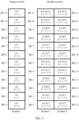
- a time-frequency resource mapping manner of the Type 1 DMRS is shown in FIG. 4 .
- the four DMRS ports are grouped into two code division multiplexing groups, where a CDM group 0 includes a port 0 and a port 1, and a CDM group 1 includes a port 2 and a port 3. Frequency division multiplexing is performed between the CDM group 0 and the CDM group 1 (that is, mapped to different frequency domain resources).
- DMRS ports included in a CDM group are mapped to a same time-frequency resource. Reference signal sequences corresponding to the DMRS ports included in the CDM group are distinguished by using cover code sequences, to ensure orthogonality of the DMRS ports in the CDM group, and further suppress interference between DMRSs whose transmission is performed on different antenna ports.
- the port 0 and the port 1 are in a same RE, and resource mapping is performed in a comb manner in frequency domain.
- adjacent frequency domain resources occupied by the port 0 and the port 1 are separated by one subcarrier.
- two adjacent occupied REs correspond to one cover code sequence whose length is 2.
- a group of cover code sequences (+1+1 and +1-1) whose lengths are 2 are used for the port 0 and the port 1.
- the port 2 and the port 3 are in a same RE, and are mapped, in a comb manner in frequency domain, to REs that are not occupied by the port 0 and the port 1.
- a group of cover code sequences (+1+1 and +1-1) whose lengths are 2 are used for the port 2 and the port 3.
- p in the table of this application is the port index
- a port whose port index is 1000 may be the port
- a port whose port index is 1001 may be the port 1
- a port whose port index is 100X may be a port X.
- the eight DMRS ports are grouped into two CDM groups, where a CDM group 0 includes a port 0, a port 1, a port 4, and a port 5, and a CDM group 1 includes a port 2, a port 3, a port 6, and a port 7.
- Frequency division multiplexing is performed between the CDM group 0 and the CDM group 1.
- DMRS ports included in a CDM group are mapped to a same time-frequency resource. Reference signal sequences corresponding to the DMRS ports included in the CDM group are distinguished by using cover code sequences.
- the port 0, the port 1, the port 4, and the port 5 are in a same RE, and resource mapping is performed in a comb manner in frequency domain.
- adjacent frequency domain resources occupied by the port 0, the port 1, the port 4, and the port 5 are separated by one subcarrier.
- two adjacent occupied subcarriers and two OFDM symbols correspond to one cover code sequence whose length is 4.
- a group of cover code sequences (+1+1+1+1/+1+1-1-1/+1-1+1-1/+1-1-1+1-1/+1-1-1+1) whose lengths are 4 are used for the port 0, the port 1, the port 4, and the port 5.
- the port 2, the port 3, the port 6, and the port 7 are in a same RE, and are mapped, in a comb manner in frequency domain, to subcarriers that are not occupied by the port 0, the port 1, the port 4, and the port 5.
- a group of cover code sequences (+1+1+1+1/+1+1-1-1/+1-1+1-1/+1-1-1+1) whose lengths are 4 are used for the port 2, the port 3, the port 6, and the port 7.
- ⁇ is an index of a CDM group (which may also be referred to as an orthogonal multiplexing group) to which the port p belongs, and DMRS ports in a same CDM group occupy a same time-frequency resource.
- CDM group which may also be referred to as an orthogonal multiplexing group
- a time-frequency resource mapping manner of the Type 2 DMRS is shown in FIG. 5 .
- a single-symbol DMRS supports a maximum of six ports, and a DMRS resource occupies one OFDM symbol.
- the six DMRS ports are grouped into three CDM groups, where a CDM group 0 includes a port 0 and a port 1, a CDM group 1 includes a port 2 and a port 3, and a CDM group 2 includes a port 4 and a port 5.
- Frequency division multiplexing is performed between CDM groups, and DMRSs corresponding to DMRS ports included in the CDM group are mapped to a same time-frequency resource.
- Reference signal sequences corresponding to the DMRS ports included in the CDM group are distinguished by using cover code sequences.
- a DMRS reference signal corresponding to the DMRS port is mapped, in frequency domain, to a plurality of resource sub-blocks including two contiguous subcarriers, and adjacent resource sub-blocks are separated by four subcarriers in frequency domain.
- the port 0 and the port 1 are in a same RE, and resource mapping is performed in a comb manner in frequency domain.
- a frequency domain resource granularity is one RB
- the port 0 and the port 1 occupy a subcarrier 0, a subcarrier 1, a subcarrier 6, and a subcarrier 7.
- the port 2 and the port 3 occupy a subcarrier 2, a subcarrier 3, a subcarrier 8, and a subcarrier 9.
- the port 4 and the port 5 occupy a subcarrier 4, a subcarrier 5, a subcarrier 10, and a subcarrier 11.
- Two DMRS ports included in one CDM group correspond, in two adjacent subcarriers, to cover code sequences (+1+1 and +1-1) whose lengths are 2.
- a double-symbol DMRS supports a maximum of twelve ports, and a DMRS resource occupies two OFDM symbols.
- the twelve DMRS ports are grouped into three CDM groups, where a CDM group 0 includes a port 0, a port 1, a port 6, and a port 7, a CDM group 1 includes a port 2, a port 3, a port 8, and a port 9, and a CDM group 2 includes a port 4, a port 5, a port 10, and a port 11.
- Frequency division multiplexing is performed between CDM groups, and DMRSs corresponding to DMRS ports included in the CDM group are mapped to a same time-frequency resource.
- Reference signal sequences corresponding to the DMRS ports included in the CDM group are distinguished by using cover code sequences.
- a DMRS reference signal corresponding to the DMRS port is mapped, in frequency domain, to a plurality of resource sub-blocks including two contiguous subcarriers, and adjacent resource sub-blocks are separated by four subcarriers in frequency domain.
- the port 0, the port 1, the port 6, and the port 7 are in a same RE, and resource mapping is performed in a comb manner in frequency domain.
- a frequency domain resource granularity is one RB
- the port 0, the port 1, the port 6, and the port 7 occupy a subcarrier 0, a subcarrier 1, a subcarrier 6, and a subcarrier 7 that correspond to an OFDM symbol 1 and an OFDM symbol 2.
- the port 2, the port 3, the port 8, and the port 9 occupy a subcarrier 2, a subcarrier 3, a subcarrier 8, and a subcarrier 9 that correspond to the OFDM symbol 1 and the OFDM symbol 2.
- the port 4, the port 5, the port 10, and the port 11 occupy a subcarrier 4, a subcarrier 5, a subcarrier 10, and a subcarrier 11 that correspond to the OFDM symbol 1 and the OFDM symbol 2.
- Four DMRS ports included in one CDM group correspond, in two adjacent subcarriers corresponding to two OFDM symbols, to cover code sequences (+1+1+1+1/+1+1-1-1/+1-1+1-1/+1-1-1+1) whose lengths are 4.
- p in the table of this application is the port index
- a port whose port index is 1000 may be the port
- a port whose port index is 1001 may be the port 1
- a port whose port index is 100X may be a port X.
- the single-symbol DMRS in NR can support the maximum of six DMRS ports, so that MIMO transmission of a maximum of six streams can be supported.
- a quantity of terminal devices further increases. This imposes a higher requirement on a quantity of MIMO transport streams.
- a quantity of transmit/receive antennas further increases (for example, a quantity of transmit antennas of a network device supports 128T or 256T, and a quantity of receive antennas of a terminal is 8R), and channel information is obtained more accurately, so that a larger quantity of transport streams can be further supported to improve spectral efficiency of the MIMO system. Therefore, more DMRS ports are needed to support the larger quantity of transport streams (more than the six streams).
- Different DMRS ports depend on frequency division multiplexing, time division multiplexing, or code division multiplexing to implement orthogonality, but time-frequency resources and orthogonal codeword sets are limited.
- a possible method for expanding an existing quantity of orthogonal DMRS ports is to increase a time-frequency resource occupied by a DMRS. According to the method, it can be ensured that a quantity of resources occupied by a DMRS symbol corresponding to each DMRS port remains unchanged. However, as a quantity of ports increases, a quantity of resources needed by the DMRS port also increases, and more time-frequency resources need to be occupied. This increases DMRS overheads. In addition, the increase in the DMRS overheads reduces the spectral efficiency of the system.
- DMRS symbols corresponding to more non-orthogonal DMRS ports are multiplexed while a same time-frequency resource (overhead) is ensured.
- a DMRS sequence with a low cross-correlation corresponding to a newly added DMRS is designed.
- a low cross-correlation is ensured between a sequence corresponding to a newly added DMRS port and a sequence corresponding to an existing DMRS port.
- superposition of the non-orthogonal ports inevitably causes specific interference, resulting in a loss of system performance (for example, a channel estimation capability).
- additional DMRS additional DMRS
- an additional DMRS configuration type is introduced in an NR standard, to track the channel change and reduce impact of a residual frequency offset and phase noise on the channel estimation capability.
- the DMRS configurations shown in FIG. 4 and FIG. 5 may be referred to as front-loaded DMRS (front-loaded DMRS) configurations.
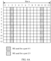
- FIG. 6A shows a configuration pattern of an additional DMRS.
- the additional DMRS corresponds to the Type 1 DMRS shown in a left figure of FIG. 4 .
- a plurality of symbols used for transmission of DMRSs may be configured in a same slot, and a DMRS pattern (DMRS pattern) on each symbol is the same as the DMRS pattern shown in the left figure of FIG. 4 .
- the DMRS pattern shown in the left figure of FIG. 4 may be a special case in which the pattern shown in FIG. 6A includes only a symbol 2 (which may also be referred to as the 2 nd symbol).
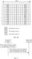
- FIG. 6B shows another configuration pattern of an additional DMRS.
- the additional DMRS corresponds to the Type 2 DMRS shown in a left figure of FIG. 5 .
- a plurality of symbols used for transmission of DMRSs may be configured in a same slot, and a DMRS pattern (DMRS pattern) on each symbol is the same as the DMRS pattern shown in the left figure of FIG. 5 .
- the DMRS pattern shown in the left figure of FIG. 5 may be a special case in which the pattern shown in FIG. 6B includes only a symbol 2 (which may also be referred to as the 2 nd symbol).
- the additional DMRS corresponds to the single-symbol DMRS is used for description. It should be understood that the additional DMRS may alternatively correspond to the double-symbol DMRS in FIG. 4 or FIG. 5 .
- the DMRS pattern of the additional DMRS patterns of a symbol 2 and a symbol 3 are the same as the DMRS pattern of the double-symbol DMRS in FIG. 4
- patterns of a symbol 10 and a symbol 11 are also the same as the DMRS pattern of the double-symbol DMRS in FIG. 4 .
- patterns of a symbol 2 and a symbol 3 are the same as the DMRS pattern of the double-symbol DMRS in FIG. 5
- patterns of a symbol 10 and a symbol 11 are also the same as the DMRS pattern of the double-symbol DMRS in FIG. 5 .
- a DMRS sequence corresponding to one port may be multiplied by a corresponding cover code sequence according to a preset time-frequency resource mapping rule, and then mapped to a corresponding time-frequency resource.
- an m th reference sequence element r(m) in a DMRS sequence corresponding to the port p may be mapped, according to the following rule, to a resource element (resource element, RE) whose index is ( k,l ) p, ⁇ .
- a value of l may be shown in Table 3.
- a value of l may be shown in Table 4.
- Table 3 l d DMRS position l PDSCH mapping type A (PDSCH mapping type A) PDSCH mapping type B (PDSCH mapping type B) Additional DMRS position (dmrs-AdditionalPosition) dmrs-AdditionalPosition Position (pos) 0 Pos 1 Pos 2 Pos 3 Pos 0 Pos 1 Pos 2 Pos 3 2 - - - l 0 0 l 0 l 0 3 l 0 l 0 0 l 0 l 0 l 0 l 0 - l 0 l 0 4 l 0 l 0 l 0 l 0 l 0 l l l l l l l 0 5 l 0 l 0 l l l l l l 0 5 l 0 l 0 l l 0 l
- l d is a quantity of continuous symbols of a PDSCH; and l 0 is a front-loaded DMRS position, which may also be referred to as a position of a start OFDM symbol occupied by a DMRS in a front-loaded DMRS configuration.
- a value of l 0 is 2; and for the pos 3, a value of l 0 is 3.
- the pos 0 indicates that one symbol may be used for transmission of the DMRS
- the pos 1 indicates that two symbols may be used for transmission of the DMRS
- the pos 2 indicates that three symbols may be used for transmission of the DMRS
- the pos 3 indicates that four symbols may be used for transmission of the DMRS.
- values of l may be l 0 and l 0 +9. That is, the transmission of the DMRS may be performed on the symbol l 0 and the symbol l 0 +9.
- a symbol occupied by the DMRS in the front-loaded DMRS configuration is a front-loaded DMRS symbol (namely, a front-loaded symbol), and a symbol used for transmission of the DMRS in the additional DMRS configuration pattern other than the front-loaded DMRS symbol is an additional DMRS symbol.
- the additional DMRS is not used to increase a quantity of DMRS ports, and a channel estimation capability in a high-speed movement case (for example, a speed of a terminal device is greater than a specified speed threshold) is ensured by repeated transmission of DMRSs only by using different OFDM symbols.
- An embodiment of this application provides a communication method.
- the method is applied to the communication system shown in FIG. 1 , and is performed by a network device or a terminal device.
- a sending device may be the network device, and a receiving device may be the terminal device; or a sending device may be the terminal device, and a receiving device may be the network device.
- a reference signal includes but is not limited to a DMRS. In the following descriptions, an example in which the reference signal is the DMRS is mainly used for description. The DMRS may be replaced with another type of reference signal based on an actual requirement.
- the communication method provided in this embodiment of this application may include the following steps.
- the sending device obtains a reference signal corresponding to a first port.
- the first port belongs to a first port set or a second port set.
- Ports in the first port set may be existing ports, for example, the port 0 and the port 1 in FIG. 4 .
- Ports in the second port set may be newly added ports.
- the first port set and the second port set are different CDM groups.
- the first port set may be a CDM group 0 or a CDM group 1; and for a single-symbol Type 2 DMRS, the first port set may be a CDM group 0, a CDM group 1, or a CDM group 2.
- the second port set may be a CDM group 3, a CDM group 4, or a CDM group 5.
- the CDM group 3 may include a port 8 and a port 9, and the CDM group 4 may include a port 10 and a port 11.
- the CDM group 3 may include a port 12 and a port 13
- the CDM group 4 may include a port 14 and a port 15
- the CDM group 5 may include a port 16 and a port 17.
- the sending device sends, by using a first resource and a second resource, the reference signal corresponding to the first port.
- the receiving device receives, by using the first resource and the second resource, the reference signal corresponding to the first port.
- the first resource may be on a first OFDM symbol
- the second resource may be on a second OFDM symbol
- the first OFDM symbol is not adjacent to the second OFDM symbol.
- the first resource and the second resource are not adjacent in time domain.
- the first resource and the second resource are respectively on a symbol 2 and a symbol 11 in a same slot.
- the first resource is an RE 1 and an RE 3 in the symbol 2
- the second resource is an RE 1 and an RE 3 in the symbol 11.
- a reference signal corresponding to the port in the first port set may correspond to a first cover code on the first resource and the second resource
- a reference signal corresponding to the port in the second port set may correspond to a second cover code on the first resource and the second resource
- the first cover code is different from the second cover code.
- the port in the first port set may be multiplexed with the port in the second port set on a same time-frequency resource in a time division orthogonal cover code (time division orthogonal cover code, TD-OCC) manner.
- TD-OCC time division orthogonal cover code
- the sending device may transmit the reference signal by using resources on a plurality of non-adjacent OFDM symbols.
- the reference signal corresponding to the port in the first port set corresponds to the first cover code on the resources on the plurality of OFDM symbols
- the reference signal corresponding to the port in the first port set corresponds to the second cover code on the resources on the plurality of OFDM symbols
- the first cover code is different from the second cover code. Therefore, a quantity of ports may be expanded by using the plurality of non-adjacent OFDM symbols, to support a larger quantity of transport streams.
- the first OFDM symbol is a front-loaded DMRS symbol
- the second OFDM symbol is an additional DMRS symbol.
- front-loaded DMRS symbol and the additional DMRS symbol refer to the following case 1 to case 4. Details are not described herein.
- the quantity of DMRS ports is increased by using an existing additional DMRS symbol, so that the quantity of DMRS ports can be increased when an additional resource is occupied, to support the larger quantity of transport streams.
- an existing DMRS port configuration is slightly changed, and a loss of channel estimation performance is not caused.
- the port in the first port set may be multiplexed, on the same time-frequency resource in the TD-OCC manner, with the port in the second port set that is newly added due to the additional DMRS symbol, for an additional DMRS, more multiplexing manners may be flexibly supported by using a port configuration. For example, repeated transmission of the DMRS is performed, or DMRSs of ports are distinguished in the TD-OCC manner.
- the method further includes:
- the network device sends first indication information to the terminal device.
- the terminal device receives the first indication information from the network device.
- the first indication information may indicate to send, in a first manner, the reference signal corresponding to the first port.
- the first manner is sending the reference signal of the first port by using the first resource and the second resource, that is, sending the reference signal of the first port in the manner of S702.
- the first indication information may be sent by using a message (for example, an RRC message), or may be carried in control information (for example, downlink control information (downlink control information, DCI)).
- a message for example, an RRC message
- control information for example, downlink control information (downlink control information, DCI)
- the first indication information may directly indicate to send, in the first manner, the reference signal corresponding to the first port.
- the first indication information may indicate to send, in the first manner, the reference signal corresponding to the first port.
- the first indication information may indirectly indicate to send, in the first manner, the reference signal corresponding to the first port.
- the first indication information includes a first port index, and the first port index indicates the first manner.
- a port index of the port H may be the first port index, where H is a nonnegative integer.
- the network device may determine that the reference signal of the first port needs to be sent in the first manner, and send the first indication information to the terminal device.
- a moving speed of the terminal device is less than a first speed threshold.
- the network device may obtain timing advances (time advances, TAs) and angles of arrival (angles of arrival, AoAs) of the terminal device at a moment 1 and a moment 2.
- the network device may determine, by using the TAs of the terminal device, a distance of the terminal device relative to the AN device, and the network device may determine, by using the AoAs, a direction of the terminal device relative to the AN device. Therefore, the network device may determine a position 1 of the terminal device at the moment 1 and a position 2 of the terminal device at the moment 2. Then, the network device may determine that the moving speed of the terminal device is (position 2-position 1)/(moment 2-moment 1). Then, the network device may determine whether the condition 1 is met.
- a channel quality change of the terminal device is less than a first channel quality threshold.
- the network device may estimate a channel of the terminal device, to determine channel quality 1 of the terminal device at a moment 3 and channel quality 2 of the terminal device at a moment 4.
- the network device may determine whether the condition 2 is met.
- Condition 3 A resource used for transmission of the DMRS is on an edge sub-band.
- the network device may determine, based on an explanation of the edge sub-band, whether the condition 3 is met.
- a total quantity of ports needed by the terminal device is greater than a quantity of ports that can be currently supported by NR.
- a quantity of ports that can be currently supported by NR For example, for the Type 1 DMRS, when a quantity of data streams that need to be transmitted by the terminal device exceeds 8, the total quantity of needed ports is also greater than 8, and therefore exceeds the quantity of ports that can be currently supported by the NR, and the condition 4 is met.
- the Type 2 DMRS when a quantity of data streams that need to be transmitted by the terminal device exceeds 12, the total quantity of needed ports is also greater than 12, and therefore exceeds the quantity of ports that can be currently supported by the NR, and the condition 4 is met.
- the terminal device may transmit, in the first manner as indicated by the network device, the reference signal corresponding to the first port.
- the network device may flexibly configure a manner in which the terminal device sends the reference signal (which may also be referred to as a DMRS port multiplexing manner), to adapt to DMRS channel estimation capabilities in different scenarios.
- the method further includes step P1 and step P2.
- the network device sends second indication information to the terminal device.
- the terminal device receives the second indication information from the network device.
- the second indication information may indicate the terminal device to send, in a second manner, the reference signal corresponding to the first port.
- the second manner is that the terminal device sends the reference signal of the first port by using a third resource and a fourth resource.
- the third resource and the fourth resource are on different frequency domain resources.
- the third resource is the RE 1 and the RE 3 in the symbol 2
- the fourth resource is an RE 5 and an RE 7 in the symbol 2.
- the reference signal corresponding to the port in the first port set may correspond to a third cover code on the third resource and the fourth resource
- the reference signal corresponding to the port in the second port set corresponds to a fourth cover code on the third resource and the fourth resource
- the third cover code is different from the fourth cover code
- the second indication information may be sent by using a message (for example, an RRC message), or may be carried in control information (for example, DCI).
- the second indication information may directly indicate to send, in the second manner, the reference signal corresponding to the first port.
- the second indication information may indicate to send, in the second manner, the reference signal corresponding to the first port.
- the second indication information may indirectly indicate to send, in the second manner, the reference signal corresponding to the first port.
- the second indication information includes a second port index, and the second port index indicates the second manner.
- a port index of the port I may be the second port index, where I is a nonnegative integer.
- the network device may determine that the reference signal of the first port needs to be sent in the second manner, and send the second indication information to the terminal device.
- Condition I A moving speed of the terminal device is greater than a second speed threshold.
- the network device may obtain the moving speed of the terminal device in a manner similar to that of the condition 1, to determine whether the condition I is met.
- Condition II Channel delay spread of the terminal device is less than a delay spread threshold.
- the network device may obtain the channel delay spread of the terminal device through channel estimation, to determine whether the condition II is met.
- Condition III A resource used for transmission of the DMRS is on a non-edge sub-band.
- the network device may determine, based on an explanation of the edge sub-band, whether the condition III is met.
- Condition IV A total quantity of ports needed by the terminal device is greater than a quantity of ports that can be currently supported by NR. For specific content, refer to the condition 4. Details are not described herein again.
- the terminal device sends, by using the third resource and the fourth resource, the reference signal corresponding to the first port.
- the network device receives, by using the third resource and the fourth resource, the reference signal corresponding to the first port.
- the terminal device may transmit, in the second manner as indicated by the network device, the reference signal corresponding to the first port.
- the network device may flexibly configure a manner in which the terminal device sends the reference signal, to adapt to DMRS channel estimation capabilities in different scenarios.
- the method when the sending device is the terminal device, the method further includes step Q1 and step Q2.
- the network device sends third indication information to the terminal device.
- the terminal device receives the third indication information from the network device.
- the third indication information indicates to send, in a third manner, the reference signal corresponding to the first port.
- the third manner is: when the first port belongs to the first port set, sending, by using a fifth resource, the reference signal corresponding to the first port; or when the first port belongs to the second port set, sending, by using a sixth resource, the reference signal corresponding to the first port.
- the fifth resource and the sixth resource are on different frequency domain resources.
- the fifth resource is the RE 1 and the RE 5 in the symbol 2
- the sixth resource is the RE 3 and the RE 7 in the symbol 2.
- the third indication information may be sent by using a message (for example, an RRC message), or may be carried in control information (for example, DCI).
- the third indication information may directly indicate to send, in the third manner, the reference signal corresponding to the first port.
- the third indication information may indicate to send, in the third manner, the reference signal corresponding to the first port.
- the third indication information may indirectly indicate to send, in the third manner, the reference signal corresponding to the first port.
- the third indication information includes a third port index, and the third port index indicates the third manner.
- a port index of the port Z may be the third port index, where Z is a nonnegative integer.
- the network device may determine that the reference signal of the first port needs to be sent in the third manner, and send the third indication information to the terminal device.
- the terminal device sends, by using the fifth resource or the sixth resource, the reference signal corresponding to the first port.
- the network device receives, by using the fifth resource or the sixth resource, the reference signal corresponding to the first port.
- the terminal device may transmit, in the third manner as indicated by the network device, the reference signal corresponding to the first port.
- the network device may flexibly configure a manner in which the terminal device sends the reference signal, to adapt to DMRS channel estimation capabilities in different scenarios.
- O1, P1 and P2, and Q1 and Q2 may be used in combination.
- the network device may indicate the terminal device to send, in the first manner and the second manner, the reference signal corresponding to the first port.
- the network device may determine to send, in the first manner and the second manner, the reference signal corresponding to the first port. For example, when the resource used for the transmission of the DMRS is on the edge sub-band, the network device may determine to send, in the first manner and the second manner, the reference signal corresponding to the first port.
- the network device may indicate the terminal device to send, in the first manner and the third manner, the reference signal corresponding to the first port.
- the network device may determine to send, in the first manner and the third manner, the reference signal corresponding to the first port.
- elements in a sequence of the reference signal corresponding to the first port are in one-to-one correspondence with REs in the first resource, and the elements in the sequence of the reference signal corresponding to the first port are in one-to-one correspondence with REs in the second resource.
- a quantity of the elements included in the sequence of the reference signal corresponding to the first port may be one of the following: 2, 4, 6, 8, and 12.
- a sequence of a reference signal 1 corresponding to the port 0 includes two elements: an element 1 and an element 2, the first resource is the RE 1 and the RE 3 in the symbol 2, and the second resource is the RE 1 and the RE 3 in the symbol 11.
- the element 1 and the element 2 may be respectively mapped to the RE 1 and the RE 3 in the symbol 2, and the element 1 and the element 2 may be respectively mapped to the RE 1 and the RE 3 in the symbol 11.
- a sequence of a reference signal 2 corresponding to the port 8 includes two elements: an element 3 and an element 4.
- the element 3 and the element 4 may be respectively mapped to the RE 1 and the RE 3 in the symbol 2, and the element 3 and the element 4 may be respectively mapped to the RE 1 and the RE 3 in the symbol 11.
- the reference signal 1 corresponds to a cover code ⁇ +1, +1 ⁇ (that is, the first cover code) on the first resource and the second resource respectively
- the reference signal 2 corresponds to a cover code ⁇ +1, -1 ⁇ (that is, the second cover code) on the first resource and the second resource respectively.
- the reference signals corresponding to the ports in both the first port set and the second port set may be repeatedly mapped to the first resource and the second resource.
- the reference signal corresponding to the port in the first port set corresponds to the first cover code on the resources on the plurality of OFDM symbols
- the reference signal corresponding to the port in the first port set corresponds to the second cover code on the resources on the plurality of OFDM symbols
- the first cover code is different from the second cover code. Therefore, the quantity of ports may be expanded by using the plurality of non-adjacent OFDM symbols, to support the larger quantity of transport streams.
- DMRSs corresponding to the ports may be distinguished based on different DMRS configuration types and different quantities of symbols, so that the quantity of ports can be expanded.
- Case 1 One group of additional DMRS symbols are added on a basis of a front-loaded single-symbol Type 1 DMRS.
- FIG. 8 shows a time-frequency resource mapping method in the case 1.
- four ports may be newly added on a basis of existing four ports (that is, a port 0 to a port 3), and port indexes of the four newly added ports may be 8 to 11.
- Both DMRSs corresponding to the existing ports and DMRSs corresponding to the newly added ports may be mapped to REs corresponding to a symbol 2 (that is, a front-loaded symbol) and a symbol 11 (that is, an additional DMRS symbol).
- the following uses the port 0, the port 1, the port 8, and the port 9 as examples to describe how to distinguish between the DMRSs corresponding to the ports.
- a first port set includes the port 0 and the port 1
- a second port set includes the port 8 and the port 9.
- Transmission of a DMRS corresponding to the first port set and a DMRS corresponding to the second port set may be performed by using a same resource.
- the DMRSs corresponding to the ports may be distinguished in one of the following manners.
- Manner A1 The DMRSs corresponding to the ports are distinguished by using TD-OCCs.
- a port in the first port set and a port in the second port set correspond to different time domain OCCs, so that a DMRS corresponding to the port in the first port set and a DMRS corresponding to the port in the second port set can be distinguished.
- ports in the first port set correspond to different frequency domain OCCs
- ports in the second port set correspond to different frequency domain OCCs, so that DMRSs corresponding to different ports can be distinguished inside the first port set and the second port set.
- Table 5A shows an example of cover code elements that correspond to DMRS sequences corresponding to the ports and that are on resources in the manner A1.
- DMRS sequences corresponding to the port 0 and the port 1 do not change, and correspond to a time domain OCC ⁇ +1, +1 ⁇ on the symbol 2 and the symbol 11 respectively.
- a DMRS sequence corresponding to the port 8 is the same as that corresponds to the existing port 0 on the symbol 2, and corresponds to a time domain OCC ⁇ +1, -1 ⁇ on the symbol 2 and the symbol 11 respectively.
- a DMRS sequence corresponding to the port 9 is the same as that corresponds to the existing port 1 on the symbol 2, and corresponds to a time domain OCC ⁇ +1, -1 ⁇ on the symbol 2 and the symbol 11 respectively.
- the DMRS corresponding to the newly added port and the DMRS corresponding to the existing port may be distinguished by using time domain OCCs with a length of 2, to implement code domain orthogonality.
- the DMRSs corresponding to the ports may also be distinguished in a manner similar to that of the port 0, the port 1, the port 8, and the port 9.
- cover code elements that correspond to DMRS sequences corresponding to the ports and that are on resources may be shown in Table 5B.
- code division orthogonality may be implemented on different time domain symbols in a TD-OCC manner to distinguish between DMRSs corresponding to different ports, so as to expand the DMRS ports by combining a plurality of symbols in time domain, that is, increase a quantity of the DMRS ports.
- the DMRSs corresponding to the ports are distinguished by using frequency division orthogonal cover codes (time division orthogonal cover codes, FD-OCCs).
- a port in the first port set and a port in the second port set correspond to different frequency domain OCCs, so that a DMRS corresponding to the port in the first port set and a DMRS corresponding to the port in the second port set can be distinguished.
- ports in the first port set correspond to different frequency domain OCCs
- ports in the second port set correspond to different frequency domain OCCs, so that DMRSs corresponding to different ports can be distinguished inside the first port set and the second port set.
- Table 6A shows an example of cover code elements that correspond to DMRS sequences corresponding to the ports and that are on resources in the manner A2.
- the existing port 0 corresponds to a frequency domain OCC ⁇ +1, +1, +1, +1 ⁇ on a subcarrier 1, a subcarrier 3, a subcarrier 5, and a subcarrier 7 respectively;
- the existing port 1 corresponds to a frequency domain OCC ⁇ +1, -1, +1, -1 ⁇ on the subcarrier 1, the subcarrier 3, the subcarrier 5, and the subcarrier 7 respectively;
- the newly added port 8 corresponds to a frequency domain OCC ⁇ +1, +1, -1, -1 ⁇ on the subcarrier 1, the subcarrier 3, the subcarrier 5, and the subcarrier 7 respectively;
- the newly added port 9 corresponds to a frequency domain OCC ⁇ +1, -1, -1, +1 ⁇ on the subcarrier 1, the subcarrier 3, the subcarrier 5, and the subcarrier 7 respectively;
- the DMRS corresponding to the newly added port and the DMRS corresponding to the existing port may be distinguished by using frequency domain OCCs with a length of 4, to implement code domain orthogonality.
- Table 6A Symbol 2 Symbol 11 Port 0 Port 1 Port 8 Port 9 Port 0 Port 1 Port 8 Port 9 Subcarrier 1 1 1 1 1 1 1 1 1 Subcarrier 3 1 -1 1 -1 1 -1 1 -1 Subcarrier 5 1 1 -1 -1 1 1 1 -1 -1 1 Subcarrier 7 1 -1 -1 1 1 1 -1 -1 1 Subcarrier 9 1 1 1 1 1 1 1 1 1 1 Subcarrier 11 1 -1 1 -1 1 -1 1 -1 Subcarrier 13 1 1 -1 -1 1 1 1 -1 -1 Subcarrier 15 1 -1 1 1 1 1 1 1 1 Subcarrier 19 1 -1 1 -1 1 -1 1 -1 Subcarrier 21 1 1 1 -1 1 1 1 1 -1 Subcarrier 23 1 -1 1 -1 1 1 -1 -1 1 -1 Subcarrier 21 1
- the DMRSs corresponding to the ports may also be distinguished in a manner similar to that of the port 0, the port 1, the port 8, and the port 9.
- cover code elements that correspond to DMRS sequences corresponding to the ports and that are on resources may be shown in Table 6B.
- code division orthogonality may be implemented on different frequency domain resources in an FD-OCC manner to distinguish between DMRSs corresponding to different ports, so as to increase a quantity of the DMRS ports.
- Manner A3 The DMRSs corresponding to the ports are distinguished by using FD-OCCs and TD-OCCs.
- a port in the first port set and a port in the second port set correspond to different time domain OCCs
- the port in the first port set and the port in the second port set correspond to different frequency domain OCCs
- a DMRS corresponding to the port in the first port set and a DMRS corresponding to the port in the second port set can be distinguished.
- ports in the first port set correspond to different frequency domain OCCs
- ports in the second port set correspond to different frequency domain OCCs, so that DMRSs corresponding to different ports can be distinguished inside the first port set and the second port set.
- Table 7A shows an example of cover code elements that correspond to DMRS sequences corresponding to the ports and that are on resources in the manner A3.
- the existing port 0 corresponds to a frequency domain OCC ⁇ +1, +1, +1, +1 ⁇ on a subcarrier 1, a subcarrier 3, a subcarrier 5, and a subcarrier 7 respectively;
- the existing port 1 corresponds to a frequency domain OCC ⁇ +1, -1, +1, -1 ⁇ on the subcarrier 1, the subcarrier 3, the subcarrier 5, and the subcarrier 7 respectively;
- the newly added port 8 corresponds to a frequency domain OCC ⁇ +1, +1, -1, -1 ⁇ on the subcarrier 1, the subcarrier 3, the subcarrier 5, and the subcarrier 7 respectively;
- the newly added port 9 corresponds to a frequency domain OCC ⁇ +1, -1, -1, +1 ⁇ on the subcarrier 1, the subcarrier 3, the subcarrier 5, and the subcarrier 7 respectively.
- the existing port 0 corresponds to a time domain OCC ⁇ +1, +1 ⁇ on the symbol 2 and the symbol 11 respectively.
- the existing port 1 corresponds to a time domain OCC ⁇ +1, +1 ⁇ on the symbol 2 and the symbol 11 respectively.
- the newly added port 8 corresponds to a time domain OCC ⁇ +1, -1 ⁇ on the symbol 2 and the symbol 11 respectively.
- the newly added port 9 corresponds to a time domain OCC ⁇ +1, -1 ⁇ on the symbol 2 and the symbol 11 respectively.
- the DMRS corresponding to the newly added port and the DMRS corresponding to the existing port may be distinguished by using time domain OCCs with a length of 2 and frequency domain OCCs with a length of 4, to implement code domain orthogonality.
- Table 7A Symbol 2 Symbol 11 Port 0 Port 1 Port 8 Port 9 Port 0 Port 1 Port 8 Port 9 Subcarrier 1 1 1 1 1 1 1 -1 -1 Subcarrier 3 1 -1 1 -1 1 -1 1 -1 -1 1 Subcarrier 5 1 1 -1 -1 1 1 1 1 1 1 1 Subcarrier 7 1 -1 -1 1 1 1 -1 1 -1 Subcarrier 9 1 1 1 1 1 1 1 1 -1 -1 Subcarrier 11 1 -1 1 -1 1 -1 1 Subcarrier 11 1 -1 1 -1 1 -1 1 Subcarrier 13 1 1 1 -1 1 1 1 1 1 Subcarrier 15 1 -1 -1 1 1 1 -1 1 -1 Subcarrier 17 1 1 1 1 1 1 1 -1 -1 Subcarrier 19 1 -1 1 -1
- the DMRSs corresponding to the ports may also be distinguished in a manner similar to that of the port 0, the port 1, the port 8, and the port 9.
- cover code elements that correspond to DMRS sequences corresponding to the ports and that are on resources may be shown in Table 7B.
- the DMRS corresponding to the newly added port and the DMRS corresponding to the existing port may be distinguished by combining the frequency domain OCC and the time domain OCC. Therefore, when a quantity of DMRS ports is increased, an interference suppression capability between the newly added port and the existing port is enhanced, channel estimation performance is improved, and a larger multiple-user (multiple user, MU) pairing gain is obtained.
- Manner A4 The DMRSs corresponding to the ports are distinguished through frequency division cyclic shift (time division cyclic shift, FD-CS) and TD-OCCs.
- a port in the first port set and a port in the second port set correspond to different time domain OCCs, and cover code sequences corresponding to the port in the first port set and the port in the second port set are orthogonal, so that a DMRS corresponding to the port in the first port set and a DMRS corresponding to the port in the second port set can be distinguished.
- ports in the first port set correspond to different frequency domain OCCs
- ports in the second port set correspond to different frequency domain OCCs, so that DMRSs corresponding to different ports can be distinguished inside the first port set and the second port set.
- Table 8A shows an example of cover code elements that correspond to DMRS sequences corresponding to the ports and that are on resources in the manner A4.
- the existing port 0 corresponds to a frequency domain cover code element ⁇ +1, +1, +1, +1 ⁇ on a subcarrier 1, a subcarrier 3, a subcarrier 5, and a subcarrier 7 respectively;
- the existing port 1 corresponds to a frequency domain cover code element ⁇ +1, -1, +1, -1 ⁇ on the subcarrier 1, the subcarrier 3, the subcarrier 5, and the subcarrier 7 respectively;
- the newly added port 8 corresponds to a frequency domain cover code element ⁇ +1, +j, -1, -j ⁇ on the subcarrier 1, the subcarrier 3, the subcarrier 5, and the subcarrier 7 respectively;
- the newly added port 9 corresponds to a frequency domain cover code element ⁇ +1, -j, -1, +j ⁇ on the subcarrier 1, the subcarrier 3, the subcarrier 5, and the subcarrier 7 respectively.
- the existing port 0 corresponds to a time domain OCC ⁇ +1, +1 ⁇ on the symbol 2 and the symbol 11 respectively.
- the existing port 1 corresponds to a time domain OCC ⁇ +1, +1 ⁇ on the symbol 2 and the symbol 11 respectively.
- the newly added port 8 corresponds to a time domain OCC ⁇ +1, -1 ⁇ on the symbol 2 and the symbol 11 respectively.
- the newly added port 9 corresponds to a time domain OCC ⁇ +1, -1 ⁇ on the symbol 2 and the symbol 11 respectively.
- the DMRS corresponding to the newly added port and the DMRS corresponding to the existing port may be distinguished by using frequency domain cover code sequences with a length of 4 and time domain OCCs with a length of 2, to implement code domain orthogonality.
- Table 8A Symbol 2 Symbol 11 Port 0 Port 1 Port 8 Port 9 Port 0 Port 1 Port 8 Port 9 Subcarrier 1 1 1 1 1 1 1 -1 -1 -1 Subcarrier 3 1 -1 j -j 1 -1 -j j Subcarrier 5 1 1 -1 -1 1 1 1 1 1 Subcarrier 7 1 -1 -j j 1 -1 j -j Subcarrier 9 1 1 1 1 1 1 1 1 -1 -1 -1 Subcarrier 11 1 -1 j -j 1 -1 -j j Subcarrier 13 1 1 -1 -1 1 1 1 1 1 Subcarrier 15 1 -1 -j j 1 -1 j -j Subcarrier 17 1 1 1 1 1 1 1 1 -1 -1 Subcarrier 19 1
- the DMRSs corresponding to the ports may also be distinguished in a manner similar to that of the port 0, the port 1, the port 8, and the port 9.
- cover code elements that correspond to DMRS sequences corresponding to the ports and that are on resources may be shown in Table 8B.
- the DMRS corresponding to the newly added port and the DMRS corresponding to the existing port may be distinguished by combining the frequency domain cover code sequence and the time domain OCC. Therefore, when a quantity of DMRS ports is increased, an interference suppression capability between the newly added port and the existing port is enhanced, channel estimation performance is improved, and a larger multiple-user (multiple user, MU) pairing gain is obtained.
- Manner A5 The DMRSs corresponding to the ports are distinguished through FDM.
- a port in the first port set and a port in the second port set correspond to different subcarriers in frequency domain, so that a DMRS corresponding to the port in the first port set and a DMRS corresponding to the port in the second port set can be distinguished.
- ports in the first port set correspond to different frequency domain OCCs
- ports in the second port set correspond to different frequency domain OCCs, so that DMRSs corresponding to different ports can be distinguished inside the first port set and the second port set.
- Table 9A shows an example of cover code elements that correspond to DMRS sequences corresponding to the ports and that are on resources in the manner A5.
- DMRSs corresponding to the existing port 0 and port 1 may be mapped to a subcarrier 1 and a subcarrier 5
- DMRSs corresponding to the newly added port 8 and port 9 may be mapped to a subcarrier 3 and a subcarrier 7.
- frequency division multiplexing may be performed between the DMRS corresponding to the newly added port and the DMRS corresponding to the existing port, to implement frequency domain orthogonality.
- the DMRSs corresponding to the ports may also be distinguished in a manner similar to that of the port 0, the port 1, the port 8, and the port 9.
- cover code elements that correspond to DMRS sequences corresponding to the ports and that are on resources may be shown in Table 9B.
- DMRSs corresponding to different ports may be distinguished on different frequency domain resources in a frequency division manner, to increase a quantity of the DMRS ports.
- Case 2 One group of additional DMRS symbols are added on a basis of a front-loaded double-symbol Type 1 DMRS.
- FIG. 9 shows a time-frequency resource mapping method in the case 2.
- eight ports may be newly added on a basis of existing eight ports (that is, a port 0 to a port 7), and port indexes of the eight newly added ports may be 8 to 15.
- Both the existing ports and the newly added ports may be mapped to REs corresponding to a symbol 2, a symbol 3, a symbol 10, and a symbol 11, where the symbol 2 and the symbol 3 are front-loaded symbols, and the symbol 10 and the symbol 11 are additional DMRS symbols.
- the following uses the port 0, the port 1, the port 4, the port 5, the port 8, the port 9, the port 12, and the port 13 as examples to describe how to distinguish between the DMRSs corresponding to the ports.
- a first port set includes the port 0, the port 1, the port 4, and the port 5, and a second port set includes the port 8, the port 9, the port 12, and the port 13.
- Transmission of a DMRS corresponding to the first port set and a DMRS corresponding to the second port set may be performed by using a same resource.
- the DMRSs corresponding to the ports may be distinguished in a manner similar to any one of the manner A1 to the manner A5. The following specifically describes some of manners.
- Manner B1 The DMRSs corresponding to the ports are distinguished by using TD-OCCs.
- the manner B1 is similar to the manner A1.
- a port in the first port set and a port in the second port set correspond to different time domain OCCs.
- DMRS sequences corresponding to the port 0, the port 1, the port 4, and the port 5 do not change, and correspond to a time domain OCC ⁇ +1, +1 ⁇ on a front-loaded symbol and an additional DMRS symbol respectively.
- DMRS sequences corresponding to the port 8, the port 9, the port 12, and the port 13 are respectively the same as those correspond to the existing port 0, port 1, port 4, and port 5 on the front-loaded symbol, and correspond to a time domain OCC ⁇ +1, -1 ⁇ on the front-loaded symbol and the additional DMRS symbol respectively.
- code division multiplexing may be performed between a DMRS corresponding to the newly added port and a DMRS corresponding to the existing port, to implement code domain orthogonality.
- Manner B2 The DMRSs corresponding to the ports are distinguished by using FD-OCCs and TD-OCCs.
- the manner B2 is similar to the manner A3.
- a port in the first port set and a port in the second port set correspond to different time domain OCCs, and the port in the first port set and the port in the second port set correspond to different frequency domain OCCs.
- Table 10A shows an example of cover code elements that correspond to DMRS sequences corresponding to the ports and that are on resources in the manner B2.
- the existing port 0 corresponds to a frequency domain OCC ⁇ +1, +1 ⁇ on a subcarrier 1 and a subcarrier 3 respectively
- the existing port 1 corresponds to a frequency domain OCC ⁇ +1, -1 ⁇ on the subcarrier 1 and the subcarrier 3 respectively
- the existing port 4 corresponds to a frequency domain OCC ⁇ +1, +1 ⁇ on the subcarrier 1 and the subcarrier 3 respectively
- the existing port 5 corresponds to a frequency domain OCC ⁇ +1, -1 ⁇ on the subcarrier 1 and the subcarrier 3 respectively
- the newly added port 8 corresponds to a frequency domain OCC ⁇ +1, +1 ⁇ on the subcarrier 1 and the subcarrier 3 respectively
- the newly added port 9 corresponds to a frequency domain OCC ⁇ +1, -1 ⁇ on the subcarrier 1 and the subcarrier 3 respectively; the newly added port 9
- the existing port 0 corresponds to a time domain OCC ⁇ +1, +1, +1, +1 ⁇ on the symbol 2, the symbol 3, the symbol 10, and the symbol 11 respectively.
- the existing port 1 corresponds to a time domain OCC ⁇ +1, +1, +1, +1 ⁇ on the symbol 2, the symbol 3, the symbol 10, and the symbol 11 respectively.
- the existing port 4 corresponds to a time domain OCC ⁇ +1, -1, +1, -1 ⁇ on the symbol 2, the symbol 3, the symbol 10, and the symbol 11 respectively.
- the existing port 5 corresponds to a time domain OCC ⁇ +1, -1, +1, -1 ⁇ on the symbol 2, the symbol 3, the symbol 10, and the symbol 11 respectively.
- the newly added port 8 corresponds to a time domain OCC ⁇ +1, +1, -1, -1 ⁇ on the symbol 2, the symbol 3, the symbol 10, and the symbol 11 respectively.
- the newly added port 9 corresponds to a time domain OCC ⁇ +1, +1, -1, -1 ⁇ on the symbol 2, the symbol 3, the symbol 10, and the symbol 11 respectively.
- the newly added port 12 corresponds to a time domain OCC ⁇ +1, +1, -1, +1 ⁇ on the symbol 2, the symbol 3, the symbol 10, and the symbol 11 respectively.
- the newly added port 13 corresponds to a time domain OCC ⁇ +1, +1, -1, +1 ⁇ on the symbol 2, the symbol 3, the symbol 10, and the symbol 11 respectively.
- a DMRS corresponding to the newly added port and a DMRS corresponding to the existing port may be distinguished by using frequency domain OCCs with a length of 2 and time domain OCCs with a length of 4, to implement code domain orthogonality.
- the DMRSs corresponding to the ports may also be distinguished in a manner similar to that of the port 0, the port 1, the port 4, the port 5, the port 8, the port 9, the port 12, and the port 13.
- cover code elements that correspond to DMRS sequences corresponding to the ports and that are on resources may be shown in Table 10B.
- Table 11A shows another example of cover code elements that correspond to DMRS sequences corresponding to the ports and that are on resources in the manner B2.
- the existing port 0 corresponds to a frequency domain OCC ⁇ +1, +1, +1, +1 ⁇ on a subcarrier 1, a subcarrier 3, a subcarrier 5, and a subcarrier 7 respectively
- the existing port 1 corresponds to a frequency domain OCC ⁇ +1, -1, +1, -1 ⁇ on the subcarrier 1, the subcarrier 3, the subcarrier 5, and the subcarrier 7 respectively
- the existing port 4 corresponds to a frequency domain OCC ⁇ +1, +1, +1, +1 ⁇ on the subcarrier 1, the subcarrier 3, the subcarrier 5, and the subcarrier 7 respectively
- the existing port 5 corresponds to a frequency domain OCC ⁇ +1, -1, +1, -1 ⁇ on the subcarrier 1, the subcarrier 3, the subcarrier 5, and the subcarrier 7 respectively
- the newly added port 8 correspond
- the existing port 0 corresponds to a time domain OCC ⁇ +1, +1, +1, +1 ⁇ on the symbol 2, the symbol 3, the symbol 10, and the symbol 11 respectively.
- the existing port 1 corresponds to a time domain OCC ⁇ +1, +1, +1, +1 ⁇ on the symbol 2, the symbol 3, the symbol 10, and the symbol 11 respectively.
- the existing port 4 corresponds to a time domain OCC ⁇ +1, -1, +1, -1 ⁇ on the symbol 2, the symbol 3, the symbol 10, and the symbol 11 respectively.
- the existing port 5 corresponds to a time domain OCC ⁇ +1, -1, +1, -1 ⁇ on the symbol 2, the symbol 3, the symbol 10, and the symbol 11 respectively.
- the newly added port 8 corresponds to a time domain OCC ⁇ +1, +1, -1, -1 ⁇ on the symbol 2, the symbol 3, the symbol 10, and the symbol 11 respectively.
- the newly added port 9 corresponds to a time domain OCC ⁇ +1, +1, -1, -1 ⁇ on the symbol 2, the symbol 3, the symbol 10, and the symbol 11 respectively.
- the newly added port 12 corresponds to a time domain OCC ⁇ +1, -1, -1, +1 ⁇ on the symbol 2, the symbol 3, the symbol 10, and the symbol 11 respectively.
- the newly added port 13 corresponds to a time domain OCC ⁇ +1, -1, -1, +1 ⁇ on the symbol 2, the symbol 3, the symbol 10, and the symbol 11 respectively.
- a DMRS corresponding to the newly added port and a DMRS corresponding to the existing port may be distinguished by using frequency domain OCCs with a length of 4 and time domain OCCs with a length of 4, to implement code domain orthogonality.
- the DMRSs corresponding to the ports may also be distinguished in a manner similar to that of the port 0, the port 1, the port 4, the port 5, the port 8, the port 9, the port 12, and the port 13.
- cover code elements that correspond to DMRS sequences corresponding to the ports and that are on resources may be shown in Table 11B.
- Case 3 One group of additional DMRS symbols are added on a basis of a front-loaded single-symbol Type 2 DMRS.
- FIG. 10 shows a time-frequency resource mapping method in the case 3.
- six ports may be newly added on a basis of existing six ports (that is, a port 0 to a port 5), and port indexes of the six newly added ports may be 12 to 17. Both the existing ports and the newly added ports may be mapped to REs corresponding to a symbol 2 (that is, a front-loaded symbol) and a symbol 11 (that is, an additional DMRS symbol).
- the following uses the port 0, the port 1, the port 12, and the port 13 as examples to describe how to distinguish between the DMRSs corresponding to the ports.
- a first port set includes the port 0 and the port 1
- a second port set includes the port 12 and the port 13.
- Transmission of a DMRS corresponding to the first port set and a DMRS corresponding to the second port set may be performed by using a same resource.
- the DMRSs corresponding to the ports may be distinguished in a manner similar to any one of the manner A1 to the manner A5. The following specifically describes some of manners.
- Manner C1 The DMRSs corresponding to the ports are distinguished by using TD-OCCs.
- the manner C1 is similar to the manner A1.
- a port in the first port set and a port in the second port set correspond to different time domain OCCs.
- Table 12A shows an example of cover code elements that correspond to DMRS sequences corresponding to the ports and that are on resources in the manner C1.
- DMRS sequences corresponding to the port 0 and the port 1 do not change, and correspond to a time domain OCC ⁇ +1, +1 ⁇ on the symbol 2 and the symbol 11 respectively.
- a DMRS sequence corresponding to the port 12 is the same as that corresponds to the existing port 0 on the symbol 2, and corresponds to a time domain OCC ⁇ +1, -1 ⁇ on the symbol 2 and the symbol 11 respectively.
- a DMRS sequence corresponding to the port 13 is the same as that corresponds to the existing port 1 on the symbol 2, and corresponds to a time domain OCC ⁇ +1, -1 ⁇ on the symbol 2 and the symbol 11 respectively.
- a DMRS corresponding to the newly added port and a DMRS corresponding to the existing port may be distinguished by using time domain OCCs with a length of 2, to implement code domain orthogonality. In the manner, a quantity of DMRS ports may be increased.
- the DMRSs corresponding to the ports may also be distinguished in a manner similar to that of the port 0, the port 1, the port 12, and the port 13.
- cover code elements that correspond to DMRS sequences corresponding to the ports and that are on resources may be shown in Table 12B.
- Table 12B Symbol 2 Symbol 11 Port 2 Port 3 Port 14 Port 15 Port 2 Port 3 Port 14 Port 15 Subcarrier 3 1 1 1 1 1 1 -1 -1
- Subcarrier 4 1 -1 1 -1 1 -1 -1 1
- Subcarrier 9 1 1 1 1 1 1 1 -1 -1
- Subcarrier 10 1 -1 1 -1 1 -1 1 -1 1 1 -1 1 1 1 1 -1 1 1
- the DMRSs corresponding to the ports may also be distinguished in a manner similar to that of the port 0, the port 1, the port 12, and the port 13.
- cover code elements that correspond to DMRS sequences corresponding to the ports and that are on resources may be shown in Table 12C.
- Table 12C Symbol 2 Symbol 11 Port 4 Port 5 Port 16 Port 17 Port 4 Port 5 Port 16 Port 17 Subcarrier 5 1 1 1 1 1 1 -1 -1 Subcarrier 6 1 -1 1 -1 1 -1 -1 1 Subcarrier 11 1 1 1 1 1 1 1 -1 -1 Subcarrier 12 1 -1 1 -1 1 -1 -1 1 1
- Manner C2 The DMRSs corresponding to the ports are distinguished by using FD-OCCs and TD-OCCs.
- the manner C2 is similar to the manner A3.
- a port in the first port set and a port in the second port set correspond to different time domain OCCs, and the port in the first port set and the port in the second port set correspond to different frequency domain OCCs.
- Table 13A shows an example of cover code elements that correspond to DMRS sequences corresponding to the ports and that are on resources in the manner C2.
- the existing port 0 corresponds to a frequency domain OCC ⁇ +1, +1, +1, +1 ⁇ on a subcarrier 1, a subcarrier 2, a subcarrier 7, and a subcarrier 8 respectively
- the existing port 1 corresponds to a frequency domain OCC ⁇ +1, -1, +1, -1 ⁇ on the subcarrier 1, the subcarrier 2, the subcarrier 7, and the subcarrier 8 respectively
- the newly added port 12 corresponds to a frequency domain OCC ⁇ +1, +1, -1, -1 ⁇ on the subcarrier 1, the subcarrier 2, the subcarrier 7, and the subcarrier 8 respectively
- the newly added port 13 corresponds to a frequency domain OCC ⁇ +1, -1, -1, +1 ⁇ on the subcarrier 1, the subcarrier 2, the subcarrier 7, and the subcarrier 8 respectively.
- the existing port 0 corresponds to a time domain OCC ⁇ +1, +1 ⁇ on the symbol 2 and the symbol 11 respectively.
- the existing port 1 corresponds to a time domain OCC ⁇ +1, +1 ⁇ on the symbol 2 and the symbol 11 respectively.
- the newly added port 12 corresponds to a time domain OCC ⁇ +1, -1 ⁇ on the symbol 2 and the symbol 11 respectively.
- the newly added port 13 corresponds to a time domain OCC ⁇ +1, -1 ⁇ on the symbol 2 and the symbol 11 respectively.
- a DMRS corresponding to the newly added port and a DMRS corresponding to the existing port may be distinguished by using frequency domain OCCs with a length of 4 and time domain OCCs with a length of 2, to implement code domain orthogonality.
- Table 13A Symbol 2 Symbol 11 Port 0 Port 1 Port 12 Port 13 Port 0 Port 1 Port 12 Port 13 Subcarrier 1 1 1 1 1 1 -1 -1 Subcarrier 2 1 -1 1 -1 1 -1 1 Subcarrier 7 1 1 -1 -1 1 1 1 1 Subcarrier 8 1 -1 -1 1 1 -1 1 -1
- the DMRSs corresponding to the ports may also be distinguished in a manner similar to that of the port 0, the port 1, the port 12, and the port 13.
- cover code elements that correspond to DMRS sequences corresponding to the ports and that are on resources may be shown in Table 13B.
- Table 13B Symbol 2 Symbol 11 Port 2 Port 3 Port 14 Port 15 Port 2 Port 3 Port 14 Port 15 Subcarrier 3 1 1 1 1 1 1 -1 -1
- Subcarrier 4 1 -1 1 -1 1 -1 -1 1
- Subcarrier 9 1 1 -1 -1 1 1 1 1 1
- Subcarrier 10 1 -1 -1 1 1 1 -1 1 -1 1 -1 -1 -1
- the DMRSs corresponding to the ports may also be distinguished in a manner similar to that of the port 0, the port 1, the port 12, and the port 13.
- cover code elements that correspond to DMRS sequences corresponding to the ports and that are on resources may be shown in Table 13C.
- Table 13C Symbol 2 Symbol 11 Port 4 Port 5 Port 16 Port 17 Port 4 Port 5 Port 16 Port 17 Subcarrier 5 1 1 1 1 1 1 -1 -1 -1 Subcarrier 6 1 -1 1 -1 1 -1 -1 1 Subcarrier 11 1 1 1 -1 -1 1 1 1 1 1 Subcarrier 12 1 -1 -1 1 1 1 -1 1 -1 -1 -1
- Case 4 One group of additional DMRS symbols are added on a basis of a front-loaded double-symbol Type 2 DMRS.
- FIG. 11 shows a time-frequency resource mapping method in the case 4.
- twelve ports may be newly added on a basis of existing twelve ports (that is, a port 0 to a port 11), and port indexes of the twelve newly added ports may be 12 to 23.
- Both the existing ports and the newly added ports may be mapped to REs corresponding to a symbol 2, a symbol 3, a symbol 10, and a symbol 11, where the symbol 2 and the symbol 3 are front-loaded symbols, and the symbol 10 and the symbol 11 are additional DMRS symbols.
- the following uses the port 0, the port 1, the port 6, the port 7, the port 12, the port 13, the port 18, and the port 19 as examples to describe how to implement orthogonality between a DMRS corresponding to the existing port and a DMRS corresponding to the newly added port.
- a first port set includes the port 0, the port 1, the port 6, and the port 7, and a second port set includes the port 12, the port 13, the port 18, and the port 19.
- Transmission of a DMRS corresponding to the first port set and a DMRS corresponding to the second port set may be performed by using a same resource.
- the DMRSs corresponding to the ports may be distinguished in a manner similar to any one of the manner A1 to the manner A5. The following specifically describes some of manners.
- Manner D1 The DMRSs corresponding to the ports are distinguished by using TD-OCCs.
- the manner D1 is similar to the manner A1.
- a port in the first port set and a port in the second port set correspond to different time domain OCCs.
- DMRS sequences corresponding to the port 0, the port 1, the port 6, and the port 7 do not change, and correspond to a time domain OCC ⁇ +1, +1 ⁇ on a front-loaded symbol and an additional DMRS symbol respectively.
- DMRS sequences corresponding to the port 12, the port 13, the port 18, and the port 19 are respectively the same as those correspond to the existing port 0, port 1, port 6, and port 7 on the front-loaded symbol, and correspond to a time domain OCC ⁇ +1, -1 ⁇ on the front-loaded symbol and the additional DMRS symbol respectively.
- code division multiplexing may be performed between the DMRS corresponding to the newly added port and the DMRS corresponding to the existing port, to implement code domain orthogonality.
- Manner D2 The DMRSs corresponding to the ports are distinguished by using FD-OCCs and TD-OCCs.
- the manner D2 is similar to the manner A3.
- a port in the first port set and a port in the second port set correspond to different time domain OCCs, and the port in the first port set and the port in the second port set correspond to different frequency domain OCCs.
- Table 14A shows an example of cover code elements that correspond to DMRS sequences corresponding to the ports and that are on resources in the manner D2.
- the existing port 0 corresponds to a frequency domain OCC ⁇ +1, +1 ⁇ on a subcarrier 1 and a subcarrier 2 respectively
- the existing port 1 corresponds to a frequency domain OCC ⁇ +1, -1 ⁇ on the subcarrier 1 and the subcarrier 2 respectively
- the existing port 6 corresponds to a frequency domain OCC ⁇ +1, +1 ⁇ on the subcarrier 1 and the subcarrier 2 respectively
- the existing port 7 corresponds to a frequency domain OCC ⁇ +1, -1 ⁇ on the subcarrier 1 and the subcarrier 2 respectively
- the newly added port 12 corresponds to a frequency domain OCC ⁇ +1, +1 ⁇ on the subcarrier 1 and the subcarrier 2 respectively
- the newly added port 13 corresponds to a frequency domain OCC ⁇ +1, -1 ⁇ on the subcarrier 1 and the subcarrier 2 respectively; the newly added port 13
- the existing port 0 corresponds to a time domain OCC ⁇ +1, +1, +1, +1 ⁇ on the symbol 2, the symbol 3, the symbol 10, and the symbol 11 respectively.
- the existing port 1 corresponds to a time domain OCC ⁇ +1, +1, +1, +1 ⁇ on the symbol 2, the symbol 3, the symbol 10, and the symbol 11 respectively.
- the existing port 6 corresponds to a time domain OCC ⁇ +1, -1, +1, -1 ⁇ on the symbol 2, the symbol 3, the symbol 10, and the symbol 11 respectively.
- the existing port 7 corresponds to a time domain OCC ⁇ +1, -1, +1, -1 ⁇ on the symbol 2, the symbol 3, the symbol 10, and the symbol 11 respectively.
- the newly added port 12 corresponds to a time domain OCC ⁇ +1, +1, -1, -1 ⁇ on the symbol 2, the symbol 3, the symbol 10, and the symbol 11 respectively.
- the newly added port 13 corresponds to a time domain OCC ⁇ +1, +1, -1, -1 ⁇ on the symbol 2, the symbol 3, the symbol 10, and the symbol 11 respectively.
- the newly added port 18 corresponds to a time domain OCC ⁇ +1, -1, -1, +1 ⁇ on the symbol 2, the symbol 3, the symbol 10, and the symbol 11 respectively.
- the newly added port 19 corresponds to a time domain OCC ⁇ +1, -1, -1, +1 ⁇ on the symbol 2, the symbol 3, the symbol 10, and the symbol 11 respectively.
- the DMRS corresponding to the newly added port and the DMRS corresponding to the existing port may be distinguished by using frequency domain OCCs with a length of 2 and time domain OCCs with a length of 4, to implement code domain orthogonality.
- the DMRSs corresponding to the ports may also be distinguished in a manner similar to that of the port 0, the port 1, the port 6, the port 7, the port 12, the port 13, the port 18, and the port 19.
- cover code elements that correspond to DMRS sequences corresponding to the ports and that are on resources may be shown in Table 14B.
- the DMRSs corresponding to the ports may also be distinguished in a manner similar to that of the port 0, the port 1, the port 6, the port 7, the port 12, the port 13, the port 18, and the port 19.
- cover code elements that correspond to DMRS sequences corresponding to the ports and that are on resources may be shown in Table 14C.
- Table 15A shows another example of cover code elements that correspond to DMRS sequences corresponding to the ports and that are on resources in the manner D2.
- the existing port 0 corresponds to a frequency domain OCC ⁇ +1, +1, +1, +1 ⁇ on a subcarrier 1, a subcarrier 2, a subcarrier 7, and a subcarrier 8 respectively
- the existing port 1 corresponds to a frequency domain OCC ⁇ +1, -1, +1, -1 ⁇ on the subcarrier 1, the subcarrier 2, the subcarrier 7, and the subcarrier 8 respectively
- the existing port 6 corresponds to a frequency domain OCC ⁇ +1, +1, +1, +1 ⁇ on the subcarrier 1, the subcarrier 2, the subcarrier 7, and the subcarrier 8 respectively
- the existing port 7 corresponds to a frequency domain OCC ⁇ +1, -1, +1, -1 ⁇ on the subcarrier 1, the subcarrier 2, the subcarrier 7, and the subcarrier 8 respectively
- the newly added port 12 corresponds to a
- the existing port 0 corresponds to a time domain OCC ⁇ +1, +1, +1, +1 ⁇ on the symbol 2, the symbol 3, the symbol 10, and the symbol 11 respectively.
- the existing port 1 corresponds to a time domain OCC ⁇ +1, +1, +1, +1 ⁇ on the symbol 2, the symbol 3, the symbol 10, and the symbol 11 respectively.
- the existing port 6 corresponds to a time domain OCC ⁇ +1, -1, +1, -1 ⁇ on the symbol 2, the symbol 3, the symbol 10, and the symbol 11 respectively.
- the existing port 7 corresponds to a time domain OCC ⁇ +1, -1, +1, -1 ⁇ on the symbol 2, the symbol 3, the symbol 10, and the symbol 11 respectively.
- the newly added port 12 corresponds to a time domain OCC ⁇ +1, +1, -1, -1 ⁇ on the symbol 2, the symbol 3, the symbol 10, and the symbol 11 respectively.
- the newly added port 13 corresponds to a time domain OCC ⁇ +1, +1, -1, -1 ⁇ on the symbol 2, the symbol 3, the symbol 10, and the symbol 11 respectively.
- the newly added port 18 corresponds to a time domain OCC ⁇ +1, -1, -1, +1 ⁇ on the symbol 2, the symbol 3, the symbol 10, and the symbol 11 respectively.
- the newly added port 19 corresponds to a time domain OCC ⁇ +1, -1, -1, +1 ⁇ on the symbol 2, the symbol 3, the symbol 10, and the symbol 11 respectively.
- the DMRS corresponding to the newly added port and the DMRS corresponding to the existing port may be distinguished by using frequency domain OCCs with a length of 4 and time domain OCCs with a length of 4, to implement code domain orthogonality.
- the DMRSs corresponding to the ports may also be distinguished in a manner similar to that of the port 0, the port 1, the port 6, the port 7, the port 12, the port 13, the port 18, and the port 19.
- cover code elements that correspond to DMRS sequences corresponding to the ports and that are on resources may be shown in Table 15B.
- the DMRSs corresponding to the ports may also be distinguished in a manner similar to that of the port 0, the port 1, the port 6, the port 7, the port 12, the port 13, the port 18, and the port 19.
- cover code elements that correspond to DMRS sequences corresponding to the ports and that are on resources may be shown in Table 15C.
- the front-loaded symbol is the symbol 2
- the additional DMRS symbol is the symbol 11
- the front-loaded symbol and the additional DMRS symbol may be other symbols shown in Table 3.
- the front-loaded symbol is the symbol 2
- the additional DMRS symbol is a symbol 9.
- the front-loaded symbols are the symbol 2 and the symbol 3
- the additional DMRS symbols are the symbol 10 and the symbol 11 is merely an example.
- the front-loaded symbol and the additional DMRS symbol may be other symbols shown in Table 4.
- the front-loaded symbols are the symbol 2 and the symbol 3, and the additional DMRS symbols are a symbol 12 and a symbol 13.
- the quantity of DMRS ports may be increased to at least twice that when no additional DMRS symbol is newly added.
- DMRSs whose transmission is performed by using one group of front-loaded symbols and one group of additional DMRS symbols may be distinguished by using TD-OCCs with a length of 2.
- DMRSs whose transmission is performed by using one group of front-loaded symbols and three groups of additional DMRS symbols may be distinguished by using TD-OCCs with a length of 4.
- an embodiment of this application provides a communication apparatus shown in FIG. 12 , and the communication apparatus may be configured to perform functions of related steps in the foregoing method embodiment.
- the functions may be implemented by hardware, or may be implemented by software or by hardware executing corresponding software.
- the hardware or the software includes one or more modules corresponding to the foregoing functions.
- a structure of the communication apparatus is shown in FIG. 12 , and includes a communication unit 1201 and a processing unit 1202.
- the communication apparatus 1200 may be used in the network device or the terminal device in the communication system shown in FIG. 1 , and may implement the communication method provided in the foregoing embodiments and examples of this application. The following describes functions of the units in the communication apparatus 1200.
- the communication unit 1201 is configured to receive and send data.
- the communication unit 1201 may be implemented by using a transceiver, for example, a mobile communication module.
- the mobile communication module may include at least one antenna, at least one filter, a switch, a power amplifier, a low noise amplifier (low noise amplifier, LNA), and the like.
- the AN device may communicate with an accessed terminal device via the mobile communication module.
- the processing unit 1202 may be configured to support the communication apparatus 1200 in performing a processing action in the foregoing method embodiment.
- the processing unit 1202 may be implemented by using a processor.
- the processor may be a central processing unit (central processing unit, CPU), or may be another general-purpose processor, a digital signal processor (digital signal processor, DSP), an application-specific integrated circuit (application-specific integrated circuit, ASIC), a field programmable gate array (field programmable gate array, FPGA) or another programmable logic device, a transistor logic device, a hardware component, or any combination thereof.
- the general-purpose processor may be a microprocessor, or may be any conventional processor.
- the communication apparatus 1200 is used in the sending device in the embodiment of this application shown in FIG. 7 .
- the following describes a specific function of the processing unit 1202 in the implementation.
- the processing unit 1202 is configured to:
- a reference signal corresponding to a port in the first port set corresponds to a first cover code on the first resource and the second resource
- a reference signal corresponding to a port in the second port set corresponds to a second cover code on the first resource and the second resource
- the first cover code is different from the second cover code
- the first OFDM symbol is a front-loaded demodulation reference signal DMRS symbol
- the second OFDM symbol is an additional DMRS symbol.
- the processing unit 1202 is specifically configured to: before sending the reference signal by using the first resource and the second resource, receive first indication information from a network device via the communication unit 1201, where the first indication information indicates to send, in a first manner, the reference signal corresponding to the first port, and the first manner is sending the reference signal of the first port by using the first resource and the second resource.
- the first indication information includes a first port index, and the first port index indicates the first manner.
- processing unit 1202 is specifically configured to:
- the second indication information includes a second port index, and the second port index indicates the second manner.
- processing unit 1202 is specifically configured to:
- the third indication information includes a third port index, and the third port index indicates the third manner.
- elements in a sequence of the reference signal corresponding to the first port are in one-to-one correspondence with resource elements REs in the first resource, and the elements in the sequence of the reference signal corresponding to the first port are in one-to-one correspondence with REs in the second resource.
- a quantity of the elements included in the sequence of the reference signal corresponding to the first port is one of the following: 2, 4, 6, 8, and 12.
- the communication apparatus 1200 is used in the receiving device in the embodiment of this application shown in FIG. 7 .
- the following describes a specific function of the processing unit 1202 in the implementation.
- the processing unit 1202 is configured to: receive, via the communication unit 1201 by using a first resource and a second resource, a reference signal corresponding to a first port, where the first port belongs to a first port set or a second port set, the first resource is on a first orthogonal frequency division multiplexing OFDM symbol, the second resource is on a second OFDM symbol, and the first OFDM symbol is not adjacent to the second OFDM symbol.
- a reference signal corresponding to a port in the first port set corresponds to a first cover code on the first resource and the second resource
- a reference signal corresponding to a port in the second port set corresponds to a second cover code on the first resource and the second resource
- the first cover code is different from the second cover code
- the first OFDM symbol is a front-loaded demodulation reference signal DMRS symbol
- the second OFDM symbol is an additional DMRS symbol.
- the processing unit 1202 is specifically configured to: before receiving, by using the first resource and the second resource, the reference signal corresponding to the first port, send first indication information via the communication unit 1201, where the first indication information indicates to send, in a first manner, the reference signal corresponding to the first port, and the first manner is sending the reference signal of the first port by using the first resource and the second resource.
- the first indication information includes a first port index, and the first port index indicates the first manner.
- processing unit 1202 is specifically configured to:
- the second indication information includes a second port index, and the second port index indicates the second manner.
- processing unit 1202 is specifically configured to:
- the third indication information includes a third port index, and the third port index indicates the third manner.
- elements in a sequence of the reference signal corresponding to the first port are in one-to-one correspondence with resource elements REs in the first resource, and the elements in the sequence of the reference signal corresponding to the first port are in one-to-one correspondence with REs in the second resource.
- a quantity of the elements included in the sequence of the reference signal corresponding to the first port is one of the following: 2, 4, 6, 8, and 12.
- division into the modules is an example, is merely logical function division, and may be other division in actual implementation.
- functional units in embodiments of this application may be integrated into one processing unit, each of the units may exist alone physically, or two or more units may be integrated into one unit.
- the integrated unit may be implemented in a form of hardware, or may be implemented in a form of a software functional unit.
- the integrated unit When the integrated unit is implemented in the form of the software functional unit and sold or used as an independent product, the integrated unit may be stored in a computer-readable storage medium. Based on such an understanding, the technical solutions of this application essentially, or the part contributing to the conventional technology, or all or a part of the technical solutions may be implemented in a form of a software product.
- the computer software product is stored in a storage medium and includes several instructions for instructing a computer device (which may be a personal computer, a server, a network device, or the like) or a processor (processor) to perform all or a part of the steps of the method described in embodiments of this application.
- the foregoing storage medium includes any medium that can store program code, such as a USB flash drive, a removable hard disk, a read-only memory (Read-Only Memory, ROM), a random access memory (Random Access Memory, RAM), a magnetic disk, or an optical disc.
- program code such as a USB flash drive, a removable hard disk, a read-only memory (Read-Only Memory, ROM), a random access memory (Random Access Memory, RAM), a magnetic disk, or an optical disc.
- an embodiment of this application provides a communication device shown in FIG. 13 , and the communication device may be configured to perform related steps in the foregoing method embodiment.
- the communication device may be used in the network device or the terminal device in the communication system shown in FIG. 1 , may implement the communication method provided in the foregoing embodiments and examples of this application, and has functions of the communication apparatus shown in FIG. 12 .
- the communication device 1300 includes a communication module 1301, a processor 1302, and a memory 1303.
- the communication module 1301, the processor 1302, and the memory 1303 are connected to each other.
- the communication module 1301, the processor 1302, and the memory 1303 are connected to each other through a bus 1304.
- the bus 1304 may be a peripheral component interconnect (peripheral component interconnect, PCI) bus, an extended industry standard architecture (extended industry standard architecture, EISA) bus, or the like.
- PCI peripheral component interconnect
- EISA extended industry standard architecture
- the bus may be classified into an address bus, a data bus, a control bus, and the like. For ease of representation, only one bold line is used for representation in FIG. 13 , but this does not mean that there is only one bus or only one type of bus.
- the communication module 1301 is configured to receive and send data, to implement communication interaction with another device.
- the communication module 1301 may be implemented by a physical interface, a communication module, a communication interface, or an input/output interface.
- the processor 1302 may be configured to support the communication device 1300 in performing a processing action in the foregoing method embodiment.
- the processor 1302 may be further configured to implement a function of the foregoing processing unit 1202.
- the processor 1302 may be a CPU, or may be another general-purpose processor, a DSP, an ASIC, an FPGA or another programmable logic device, a transistor logic device, a hardware component, or any combination thereof.
- the general-purpose processor may be a microprocessor, or may be any conventional processor.
- the communication device 1300 is used in the sending device in the embodiment of this application shown in FIG. 7 .
- the processor 1302 is specifically configured to:
- a reference signal corresponding to a port in the first port set corresponds to a first cover code on the first resource and the second resource
- a reference signal corresponding to a port in the second port set corresponds to a second cover code on the first resource and the second resource
- the first cover code is different from the second cover code
- the communication device 1300 is used in the receiving device in the embodiment of this application shown in FIG. 7 .
- the processor 1302 is specifically configured to: receive, via the communication module 1301 by using a first resource and a second resource, a reference signal corresponding to a first port, where the first port belongs to a first port set or a second port set, the first resource is on a first orthogonal frequency division multiplexing OFDM symbol, the second resource is on a second OFDM symbol, and the first OFDM symbol is not adjacent to the second OFDM symbol.
- a reference signal corresponding to a port in the first port set corresponds to a first cover code on the first resource and the second resource
- a reference signal corresponding to a port in the second port set corresponds to a second cover code on the first resource and the second resource
- the first cover code is different from the second cover code
- processor 1302 For a specific function of the processor 1302, refer to the descriptions in the communication method provided in the foregoing embodiments and examples of this application, and the specific function descriptions of the communication apparatus 1200 in the embodiment of this application shown in FIG. 12 . Details are not described herein again.
- the memory 1303 is configured to store program instructions, data, and the like.
- the program instructions may include program code, and the program code includes computer operation instructions.
- the memory 1303 may include a RAM, or may include a non-volatile memory (non-volatile memory), for example, at least one magnetic disk storage.
- the processor 1302 executes the program instructions stored in the memory 1303, and implements the foregoing functions by using the data stored in the memory 1303, to implement the communication method provided in the foregoing embodiments of this application.
- the memory 1303 in FIG. 13 in this application may be a volatile memory or a non-volatile memory, or may include both a volatile memory and a non-volatile memory.
- the non-volatile memory may be a ROM, a programmable read-only memory (Programmable ROM, PROM), an erasable programmable read-only memory (Erasable PROM, EPROM), an electrically erasable programmable read-only memory (Electrically EPROM, EEPROM), or a flash memory.
- the volatile memory may be the RAM, and serves as an external cache.
- RAMs in many forms may be used, for example, a static random access memory (Static RAM, SRAM), a dynamic random access memory (Dynamic RAM, DRAM), a synchronous dynamic random access memory (Synchronous DRAM, SDRAM), a double data rate synchronous dynamic random access memory (Double Data Rate SDRAM, DDR SDRAM), an enhanced synchronous dynamic random access memory (Enhanced SDRAM, ESDRAM), a synchlink dynamic random access memory (Synchlink DRAM, SLDRAM), and a direct rambus random access memory (Direct Rambus RAM, DR RAM).
- Static RAM static random access memory
- DRAM dynamic random access memory
- DRAM synchronous dynamic random access memory
- SDRAM double data rate synchronous dynamic random access memory
- Enhanced SDRAM, ESDRAM enhanced synchronous dynamic random access memory
- Synchlink DRAM, SLDRAM synchlink dynamic random access memory
- Direct Rambus RAM Direct Rambus RAM
- an embodiment of this application further provides a computer program.
- the computer program When the computer program is run on a computer, the computer is enabled to perform the method provided in the foregoing embodiment.
- an embodiment of this application further provides a computer-readable storage medium.
- the computer-readable storage medium stores a computer program.
- the computer program When the computer program is executed by a computer, the computer is enabled to perform the method provided in the foregoing embodiment.
- the storage medium may be any usable medium that can be accessed by the computer.
- the following provides an example but does not impose a limitation:
- the computer-readable medium may include a RAM, a ROM, an EEPROM, a CD-ROM or another optical disc storage, a disk storage medium or another disk storage device, or any other medium that can be used to carry or store expected program code in a form of an instruction or a data structure and that can be accessed by the computer.
- an embodiment of this application further provides a chip.
- the chip is configured to read a computer program stored in a memory, to implement the method provided in the foregoing embodiment.
- an embodiment of this application provides a chip system.
- the chip system includes a processor, configured to support a computer apparatus in implementing functions of the devices in the foregoing embodiments.
- the chip system further includes a memory, and the memory is configured to store a program and data that are necessary for the computer apparatus.
- the chip system may include a chip, or may include a chip and another discrete device.
- a sending device may send the reference signal by using a first resource and a second resource.
- the first port belongs to a first port set or a second port set, the first resource is on a first OFDM symbol, the second resource is on a second OFDM symbol, and the first OFDM symbol is not adjacent to the second OFDM symbol.
- a reference signal corresponding to a port in the first port set corresponds to a first cover code on the first resource and the second resource
- a reference signal corresponding to a port in the second port set corresponds to a second cover code on the first resource and the second resource
- the first cover code is different from the second cover code.
- the sending device may transmit the reference signal by using resources on a plurality of non-adjacent OFDM symbols.
- the reference signal corresponding to the port in the first port set corresponds to the first cover code on the resources on the plurality of OFDM symbols
- the reference signal corresponding to the port in the first port set corresponds to the second cover code on the resources on the plurality of OFDM symbols
- the first cover code is different from the second cover code. Therefore, a quantity of ports may be expanded by using the plurality of non-adjacent OFDM symbols, to support a larger quantity of transport streams.
- this application may be provided as a method, a system, or a computer program product. Therefore, this application may use a form of hardware-only embodiments, software-only embodiments, or embodiments with a combination of software and hardware. In addition, this application may use a form of a computer program product that is implemented on one or more computer-usable storage media (including but not limited to a magnetic disk storage, a CD-ROM, an optical memory, and the like) that include computer-usable program code.
- computer-usable storage media including but not limited to a magnetic disk storage, a CD-ROM, an optical memory, and the like
- the computer program instructions may alternatively be stored in a computer-readable memory that can instruct a computer or another programmable data processing device to work in a specific manner, so that the instructions stored in the computer-readable memory generate an artifact that includes an instruction apparatus.
- the instruction apparatus implements a specific function in one or more procedures in the flowcharts and/or in one or more blocks in the block diagrams.
- the computer program instructions may alternatively be loaded onto a computer or another programmable data processing device, so that a series of operations and steps are performed on the computer or the another programmable device, to generate computer-implemented processing. Therefore, the instructions executed on the computer or the another programmable device provide steps for implementing a specific function in one or more procedures in the flowcharts and/or in one or more blocks in the block diagrams.
Landscapes
- Engineering & Computer Science (AREA)
- Signal Processing (AREA)
- Computer Networks & Wireless Communication (AREA)
- Mobile Radio Communication Systems (AREA)
Applications Claiming Priority (2)
| Application Number | Priority Date | Filing Date | Title |
|---|---|---|---|
| CN202210476540.1A CN114884634B (zh) | 2022-04-29 | 2022-04-29 | 一种通信方法、装置及设备 |
| PCT/CN2023/084299 WO2023207476A1 (zh) | 2022-04-29 | 2023-03-28 | 一种通信方法、装置及设备 |
Publications (2)
| Publication Number | Publication Date |
|---|---|
| EP4507232A1 true EP4507232A1 (de) | 2025-02-12 |
| EP4507232A4 EP4507232A4 (de) | 2025-07-09 |
Family
ID=82674315
Family Applications (1)
| Application Number | Title | Priority Date | Filing Date |
|---|---|---|---|
| EP23794911.0A Pending EP4507232A4 (de) | 2022-04-29 | 2023-03-28 | Kommunikationsverfahren und -vorrichtung sowie vorrichtung |
Country Status (4)
| Country | Link |
|---|---|
| US (1) | US20250055611A1 (de) |
| EP (1) | EP4507232A4 (de) |
| CN (1) | CN114884634B (de) |
| WO (1) | WO2023207476A1 (de) |
Families Citing this family (5)
| Publication number | Priority date | Publication date | Assignee | Title |
|---|---|---|---|---|
| CN114884634B (zh) * | 2022-04-29 | 2024-07-05 | 华为技术有限公司 | 一种通信方法、装置及设备 |
| CN117811713A (zh) * | 2022-10-01 | 2024-04-02 | 华为技术有限公司 | 一种通信方法、装置及设备 |
| US20240322930A1 (en) * | 2023-03-24 | 2024-09-26 | Samsung Electronics Co., Ltd. | Devices and methods for wireless communication using advanced demodulation reference signals |
| CN118945015A (zh) * | 2023-05-12 | 2024-11-12 | 华为技术有限公司 | 一种指示参考信号端口的方法和通信装置 |
| CN116684052B (zh) * | 2023-05-31 | 2026-01-09 | 华为技术有限公司 | 通信方法与通信装置 |
Family Cites Families (13)
| Publication number | Priority date | Publication date | Assignee | Title |
|---|---|---|---|---|
| KR101792880B1 (ko) * | 2010-04-20 | 2017-11-03 | 엘지전자 주식회사 | 무선 통신 시스템에서 참조 신호 전송 방법 및 장치 |
| CN102271109B (zh) * | 2010-06-07 | 2015-08-12 | 中兴通讯股份有限公司 | 一种解调参考符号的映射方法及系统 |
| EP4708714A2 (de) * | 2017-03-23 | 2026-03-11 | Innovative Technology Lab Co., Ltd. | Verfahren und vorrichtung zum übertragen und empfangen eines demodulationsreferenzsignals |
| KR20190013636A (ko) * | 2017-07-31 | 2019-02-11 | 주식회사 케이티 | 차세대 무선망에서 부가 dmrs를 설정하는 방법 및 그 장치 |
| CN108111273B (zh) * | 2017-08-11 | 2021-11-02 | 中兴通讯股份有限公司 | 参考信号的传输方法及装置 |
| CN110166194B (zh) * | 2018-02-12 | 2020-09-08 | 华为技术有限公司 | 一种导频信号生成方法及装置 |
| WO2020029228A1 (zh) * | 2018-08-10 | 2020-02-13 | 株式会社Ntt都科摩 | 解调参考信号的资源分配方法和基站 |
| CN110890946B (zh) * | 2018-09-07 | 2023-01-17 | 中国移动通信有限公司研究院 | 解调参考信号的传输方法、网络侧设备及用户设备 |
| US11743899B2 (en) * | 2020-05-15 | 2023-08-29 | Lg Electronics Inc. | Method and apparatus for transmitting/receiving wireless signal in wireless communication system |
| CN114079555B (zh) * | 2020-08-14 | 2025-06-17 | 华为技术有限公司 | 信号传输方法和装置 |
| CN120691999A (zh) * | 2020-08-14 | 2025-09-23 | 华为技术有限公司 | 信号传输方法和装置 |
| CN114338322A (zh) * | 2020-09-30 | 2022-04-12 | 华为技术有限公司 | 参考信号的映射方法及装置 |
| CN114884634B (zh) * | 2022-04-29 | 2024-07-05 | 华为技术有限公司 | 一种通信方法、装置及设备 |
-
2022
- 2022-04-29 CN CN202210476540.1A patent/CN114884634B/zh active Active
-
2023
- 2023-03-28 WO PCT/CN2023/084299 patent/WO2023207476A1/zh not_active Ceased
- 2023-03-28 EP EP23794911.0A patent/EP4507232A4/de active Pending
-
2024
- 2024-10-28 US US18/928,552 patent/US20250055611A1/en active Pending
Also Published As
| Publication number | Publication date |
|---|---|
| US20250055611A1 (en) | 2025-02-13 |
| CN114884634A (zh) | 2022-08-09 |
| CN114884634B (zh) | 2024-07-05 |
| EP4507232A4 (de) | 2025-07-09 |
| WO2023207476A1 (zh) | 2023-11-02 |
Similar Documents
| Publication | Publication Date | Title |
|---|---|---|
| EP4507232A1 (de) | Kommunikationsverfahren und -vorrichtung sowie vorrichtung | |
| JP5468606B2 (ja) | 反復重複のあるシンボルのリソース・ブロック・マッピング | |
| US11272491B2 (en) | Resource indication method, network device, and terminal device | |
| US9337907B2 (en) | Radio communication system, radio base station apparatus, user terminal and radio communication method | |
| US10461822B2 (en) | Communication method, network device, and terminal device | |
| CN114071723A (zh) | 一种通信方法及装置 | |
| EP4398530B1 (de) | Verfahren und vorrichtung zur übertragung einer protokolldateneinheit der physikalischen schicht | |
| CN109792425B (zh) | 无线通信中的虚拟符号划分技术 | |
| WO2020020351A1 (zh) | 接收和发送数据的方法以及通信装置 | |
| EP3633940B1 (de) | Verfahren und vorrichtung zur kanalschätzung | |
| EP4213454A1 (de) | Verfahren und vorrichtung zur zuordnung von referenzsignalen | |
| WO2023125761A1 (zh) | 一种通信方法及装置 | |
| CN104247537A (zh) | 无线通信系统、基站装置以及无线通信方法 | |
| US20190386723A1 (en) | Signal transmission method and apparatus | |
| WO2024067265A1 (zh) | 一种通信方法、装置及设备 | |
| WO2023125697A1 (zh) | 一种通信方法、装置及设备 | |
| WO2020020354A1 (zh) | 接收和发送数据的方法以及通信装置 | |
| CN117121414A (zh) | 用于传输参考信号的方法和装置 | |
| US20230345284A1 (en) | Downlink signal processing method and apparatus | |
| WO2023246525A1 (zh) | 数据传输方法、设备、装置及存储介质 | |
| WO2025194604A1 (en) | Methods, apparatus, and systems for frequency-division multiplexing of discrete fourier transform-spread signals | |
| WO2026066502A1 (zh) | 通信方法及装置 | |
| JP2016106499A (ja) | 無線通信システム、無線基地局装置、ユーザ端末及び無線通信方法 |
Legal Events
| Date | Code | Title | Description |
|---|---|---|---|
| STAA | Information on the status of an ep patent application or granted ep patent |
Free format text: STATUS: THE INTERNATIONAL PUBLICATION HAS BEEN MADE |
|
| PUAI | Public reference made under article 153(3) epc to a published international application that has entered the european phase |
Free format text: ORIGINAL CODE: 0009012 |
|
| STAA | Information on the status of an ep patent application or granted ep patent |
Free format text: STATUS: REQUEST FOR EXAMINATION WAS MADE |
|
| 17P | Request for examination filed |
Effective date: 20241104 |
|
| AK | Designated contracting states |
Kind code of ref document: A1 Designated state(s): AL AT BE BG CH CY CZ DE DK EE ES FI FR GB GR HR HU IE IS IT LI LT LU LV MC ME MK MT NL NO PL PT RO RS SE SI SK SM TR |
|
| A4 | Supplementary search report drawn up and despatched |
Effective date: 20250611 |
|
| RIC1 | Information provided on ipc code assigned before grant |
Ipc: H04L 27/26 20060101ALI20250604BHEP Ipc: H04L 5/00 20060101AFI20250604BHEP |
|
| DAV | Request for validation of the european patent (deleted) | ||
| DAX | Request for extension of the european patent (deleted) |