EP4507329A1 - Dispositif de sortie acoustique - Google Patents
Dispositif de sortie acoustique Download PDFInfo
- Publication number
- EP4507329A1 EP4507329A1 EP22966037.8A EP22966037A EP4507329A1 EP 4507329 A1 EP4507329 A1 EP 4507329A1 EP 22966037 A EP22966037 A EP 22966037A EP 4507329 A1 EP4507329 A1 EP 4507329A1
- Authority
- EP
- European Patent Office
- Prior art keywords
- panel
- acoustic output
- output device
- shell
- magnetic circuit
- Prior art date
- Legal status (The legal status is an assumption and is not a legal conclusion. Google has not performed a legal analysis and makes no representation as to the accuracy of the status listed.)
- Pending
Links
Images















Classifications
-
- H—ELECTRICITY
- H04—ELECTRIC COMMUNICATION TECHNIQUE
- H04R—LOUDSPEAKERS, MICROPHONES, GRAMOPHONE PICK-UPS OR LIKE ACOUSTIC ELECTROMECHANICAL TRANSDUCERS; ELECTRIC HEARING AIDS; PUBLIC ADDRESS SYSTEMS
- H04R9/00—Transducers of moving-coil, moving-strip, or moving-wire type
- H04R9/06—Loudspeakers
- H04R9/066—Loudspeakers using the principle of inertia
-
- H—ELECTRICITY
- H04—ELECTRIC COMMUNICATION TECHNIQUE
- H04R—LOUDSPEAKERS, MICROPHONES, GRAMOPHONE PICK-UPS OR LIKE ACOUSTIC ELECTROMECHANICAL TRANSDUCERS; ELECTRIC HEARING AIDS; PUBLIC ADDRESS SYSTEMS
- H04R1/00—Details of transducers, loudspeakers or microphones
- H04R1/20—Arrangements for obtaining desired frequency or directional characteristics
- H04R1/22—Arrangements for obtaining desired frequency or directional characteristics for obtaining desired frequency characteristic only
- H04R1/28—Transducer mountings or enclosures modified by provision of mechanical or acoustic impedances, e.g. resonator, damping means
- H04R1/2807—Enclosures comprising vibrating or resonating arrangements
- H04R1/2811—Enclosures comprising vibrating or resonating arrangements for loudspeaker transducers
-
- H—ELECTRICITY
- H04—ELECTRIC COMMUNICATION TECHNIQUE
- H04R—LOUDSPEAKERS, MICROPHONES, GRAMOPHONE PICK-UPS OR LIKE ACOUSTIC ELECTROMECHANICAL TRANSDUCERS; ELECTRIC HEARING AIDS; PUBLIC ADDRESS SYSTEMS
- H04R9/00—Transducers of moving-coil, moving-strip, or moving-wire type
- H04R9/02—Details
- H04R9/025—Magnetic circuit
-
- H—ELECTRICITY
- H04—ELECTRIC COMMUNICATION TECHNIQUE
- H04R—LOUDSPEAKERS, MICROPHONES, GRAMOPHONE PICK-UPS OR LIKE ACOUSTIC ELECTROMECHANICAL TRANSDUCERS; ELECTRIC HEARING AIDS; PUBLIC ADDRESS SYSTEMS
- H04R9/00—Transducers of moving-coil, moving-strip, or moving-wire type
- H04R9/02—Details
- H04R9/04—Construction, mounting, or centering of coil
- H04R9/045—Mounting
-
- H—ELECTRICITY
- H04—ELECTRIC COMMUNICATION TECHNIQUE
- H04R—LOUDSPEAKERS, MICROPHONES, GRAMOPHONE PICK-UPS OR LIKE ACOUSTIC ELECTROMECHANICAL TRANSDUCERS; ELECTRIC HEARING AIDS; PUBLIC ADDRESS SYSTEMS
- H04R9/00—Transducers of moving-coil, moving-strip, or moving-wire type
- H04R9/06—Loudspeakers
-
- H—ELECTRICITY
- H04—ELECTRIC COMMUNICATION TECHNIQUE
- H04R—LOUDSPEAKERS, MICROPHONES, GRAMOPHONE PICK-UPS OR LIKE ACOUSTIC ELECTROMECHANICAL TRANSDUCERS; ELECTRIC HEARING AIDS; PUBLIC ADDRESS SYSTEMS
- H04R1/00—Details of transducers, loudspeakers or microphones
- H04R1/10—Earpieces; Attachments therefor ; Earphones; Monophonic headphones
- H04R1/1058—Manufacture or assembly
- H04R1/1075—Mountings of transducers in earphones or headphones
-
- H—ELECTRICITY
- H04—ELECTRIC COMMUNICATION TECHNIQUE
- H04R—LOUDSPEAKERS, MICROPHONES, GRAMOPHONE PICK-UPS OR LIKE ACOUSTIC ELECTROMECHANICAL TRANSDUCERS; ELECTRIC HEARING AIDS; PUBLIC ADDRESS SYSTEMS
- H04R11/00—Transducers of moving-armature or moving-core type
- H04R11/02—Loudspeakers
-
- H—ELECTRICITY
- H04—ELECTRIC COMMUNICATION TECHNIQUE
- H04R—LOUDSPEAKERS, MICROPHONES, GRAMOPHONE PICK-UPS OR LIKE ACOUSTIC ELECTROMECHANICAL TRANSDUCERS; ELECTRIC HEARING AIDS; PUBLIC ADDRESS SYSTEMS
- H04R2400/00—Loudspeakers
- H04R2400/07—Suspension between moving magnetic core and housing
-
- H—ELECTRICITY
- H04—ELECTRIC COMMUNICATION TECHNIQUE
- H04R—LOUDSPEAKERS, MICROPHONES, GRAMOPHONE PICK-UPS OR LIKE ACOUSTIC ELECTROMECHANICAL TRANSDUCERS; ELECTRIC HEARING AIDS; PUBLIC ADDRESS SYSTEMS
- H04R2460/00—Details of hearing devices, i.e. of ear- or headphones covered by H04R1/10 or H04R5/033 but not provided for in any of their subgroups, or of hearing aids covered by H04R25/00 but not provided for in any of its subgroups
- H04R2460/13—Hearing devices using bone conduction transducers
Definitions
- the present disclosure relates to a field of acoustic technology, and in particular, to acoustic output devices.
- the loudspeakers typically include a bone conduction loudspeaker and an air-conduction loudspeaker.
- the bone conduction loudspeaker can convert electrical signals into mechanical vibration signals, and then transmit the mechanical vibration signals to the auditory nerves of the human body through body tissues and bones, allowing a wearer to hear sounds.
- the additional element(s) e.g., a microphone, a sensor, an air-conduction loudspeaker, a battery, a circuit board, etc.
- the additional element(s) and a magnetic circuit assembly in a transducer device may attract or repel to each other, causing deformation or inversion of the magnetic circuit assembly.
- the acoustic output device may include a transducer, a housing, and an additional element.
- the transducer device may be configured to generate a mechanical vibration based on an electrical signal.
- the transducer device may include a magnetic circuit assembly and an elastic support component.
- the housing may be configured to accommodate the transducer device.
- the housing may include a panel and a shell, and the transducer device may transmit the mechanical vibration to a user through the panel.
- the additional element may be connected to the panel through a vibration path, and the vibration path at least may include an elastic element.
- the additional element may be located at a sidewall of the shell adjacent to the panel, and the elastic support component may connect the magnetic circuit assembly and the sidewall disposed with the additional element.
- an acoustic output device including a transducer device, a panel and a back panel opposite to the panel, a support component, and an additional element.
- the transducer device may be configured to generate a mechanical vibration based on an electrical signal.
- the transducer device may include a magnetic circuit assembly and an elastic support component.
- the panel may be rigidly connected to the back panel through a housing body, and the transducer device may transmit the mechanical vibration to a user through the panel.
- the additional element may be rigidly connected to the support component.
- the support component may be disposed between a plane in which the panel is located and a plane in which the back panel is located.
- the support component may be connected to a housing through an elastic element.
- the magnetic circuit assembly may be connected to the housing body or the support component through the elastic support component.
- One embodiment of the present disclosure further provides an acoustic output device including a transducer device, a panel and a back panel opposite to the panel, a support component, and an additional element.
- the transducer device may be configured to generate a mechanical vibration based on an electrical signal.
- the transducer device may include a magnetic circuit assembly and an elastic support component.
- the panel may be rigidly connected to the back panel through a housing body, and the transducer device may transmit the mechanical vibration to a user through the panel.
- the additional element may be rigidly connected to the support component.
- the support component may be disposed between a plane in which the panel is located and a plane in which the back panel is located.
- the support component may be connected to a housing through an elastic element.
- the magnetic circuit assembly may be connected to the housing body or the support component through the elastic support component.
- the magnetic circuit assembly may include an aperture portion and a positioning rod.
- the aperture portion may penetrate the magnetic circuit assembly in a vibration direction of the transducer device.
- An end of the positioning rod away from the panel may be connected to the back panel in the housing body opposite to the panel, and another end of the positioning rod passes through the aperture portion and may be connected to the panel.
- the acoustic output device may include a transducer device, a housing, and an additional element.
- the transducer device may be configured to generate a mechanical vibration based on an electrical signal.
- the transducer device may include a magnetic circuit assembly and an elastic support component.
- the housing may be configured to accommodate the transducer device.
- the housing may include a panel and a shell.
- the transducer device may transmit the mechanical vibration to a user through the panel.
- the additional element may be connected to the panel through a vibration path, and the vibration path may at least include an elastic element.
- the additional element may be located at a sidewall of the shell adjacent to the panel, and the elastic support component may connect the magnetic circuit assembly and the sidewall disposed with the additional element.
- a vibration transmission sheet (also referred to as the elastic support component) in the transducer device may connect the magnetic circuit assembly and the sidewall of the shell adjacent to the panel. That is, the vibration transmission sheet connects the magnetic circuit assembly and the sidewall of the shell disposed with the additional element.
- the transducer device may include at least two vibration transmission sheets. One of the at least two vibration transmission sheets may be disposed on a side of the transducer device facing the panel, so as to elastically connect the transducer device and the panel.
- the other one of the at least two vibration transmission sheets may be disposed on a side of the transducer device back away from the panel, so as to connect the transducer device and the shell, and support the transducer device to ensure that the transducer device can vibrate stably along an axial direction.
- the vibration transmission sheet disposed on the side of the transducer device back away from the panel may connect the magnetic circuit assembly and the sidewall of the shell where the additional element is disposed, so as to reduce or avoid the problem that the additional element and the magnetic circuit assembly in the transducer device may attract or repel each other, causing deformation or inversion of the magnetic circuit assembly.
- the vibration transmission sheet of the transducer device may connect the magnetic circuit assembly and the elastic support component.
- the vibration transmission sheet can provide support in a relative movement direction between the magnetic circuit assembly and the additional element, so that the vibration transmission sheet can provide better support for the magnetic circuit assembly, thereby improving the stability between the magnetic circuit assembly and the shell. This can prevent the additional element and the magnetic circuit assembly in the transducer device from attracting or repelling to each other and causing the deformation or inversion of the magnetic circuit assembly, thereby ensuring that the vibration of the transducer device is relatively stable.
- the additional element and the magnetic circuit assembly can vibrate with respect to the panel to generate a resonance peak located within a target frequency, which ensures that the sensitivity of the acoustic output device is not affected by the additional element when the acoustic output device is within a frequency range that is greater than a resonance frequency corresponding to the resonance peak.
- the sensitivity of the acoustic output device disposed with the additional element is not affected by the additional element when the acoustic output device is within the frequency range that is greater than the resonance frequency, and the problem that a sensitivity of a bone conduction acoustic output device is weakened due to the additional installation of the additional element on the bone conduction loudspeaker can be avoided.
- a frequency response curve of the acoustic output device can be relatively flat, which ensures that the acoustic output device has a better acoustic output effect, improving the user's listening experience.
- low frequency (lower than the frequency range of the resonance frequency corresponding to the resonance peak) vibrations of the panel can be transmitted to the additional element to drive the additional element to vibrate with the low frequency vibrations of the panel.
- a mass of the additional element can increase a loading mass of the vibration of the transducer device, which causes that the sensitivity of the acoustic output device is affected by the additional element in a frequency range lower than the frequency range of the resonance frequency corresponding to the resonance peak.
- the transducer device When the transducer device generates high frequency (higher than the frequency range of the resonance frequency corresponding to the resonance peak) mechanical vibrations, high frequency vibrations of the panel can not lead to vibrations of the additional element due to an elastic connection (e.g., the presence of the vibration transmission sheet) between the additional element and/or the magnetic circuit assembly and the panel, and the mass of the additional element does not affect the loading mass of the vibration of the transducer device. This ensures that the sensitivity of the acoustic output device is not affected by the additional element in a frequency range higher than the frequency range of the resonance frequency corresponding to the resonance peak.
- an elastic connection e.g., the presence of the vibration transmission sheet
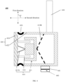
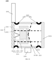
- FIG. 1 is a schematic diagram illustrating an exemplary acoustic output device 100 according to some embodiments of the present disclosure.
- the acoustic output device 100 may include a transducer device 10 and a housing 20 configured to accommodate the transducer device 10.
- the housing 20 may include a panel 21 and a shell 22.
- the shell 22 may be a structural body with a hollow interior, and the panel 21 and the shell 22 may form an accommodating chamber to accommodate the transducer device 10.
- the transducer device 10 may be connected to the panel 21, and the transducer device 10 may transmit a mechanical vibration to a user through the panel 21.
- the panel 21 and the shell 22 may be an integrated structure.
- the shell 22 may be an integrated structure or a structure formed by connecting multiple components.
- the shell 22 may include an annular side panel and a back panel.
- the back panel may be fixed to a side of the annular side panel opposite to the panel 21, so as to form the shell 22.
- the panel 21 and the shell 22 may also be independent structures.
- the shell 22 may be a structural body that has a hollow interior and an open opening at one end.
- the panel 21 may be rigidly connected to the end of the shell 22 that has the open opening, and cover the open opening of the shell 22 to form the accommodating chamber for accommodating the transducer device 10.
- the panel 21 when the user wears the acoustic output device 100, the panel 21 may fit against the user's head, and then transmit the mechanical vibration to the user's auditory nerves through the body tissues and bones, enabling the user to hear bone conduction sound.
- the rigid connection in the present disclosure refers to a connection between two connecting members (e.g., the panel 21 and the shell 22) such that when one (e.g., a first connecting member) of the connecting members is displaced or deformed with respect to the other connecting member (e.g., a second connecting member), the other connecting member connected thereto is substantially free from displacement or deformation relative to the first connecting member. That is, the two connecting members may be substantially considered as a whole during the vibration process.
- two connecting members are directly connected to each other, and an overall tensile strength (Pa) of the two connecting members is greater than 50% of a tensile strength of a base material of either of the two connecting members.
- the two connecting members are connected by a rigid connecting element, and a tensile strength of the rigid connecting element is greater than the tensile strength of the base material of either of the two connecting members.
- the rigid connection also refers to that high frequency vibrations (e.g., vibrations whose vibration frequency is greater than 6 kilohertz (KHz), 8 KHz, or 10 KHz) can be efficiently transmitted between the two connecting members.
- KHz 6 kilohertz
- the rigid connection also refers to that a resonance frequency generated by the vibration transmission between the two connecting members is relatively high.
- the resonance frequency generated by the vibration transmission between the two connecting members is greater than 6000 Hz.
- the resonance frequency generated by the vibration transmission between the two connecting members is greater than 8000 Hz.
- the resonance frequency generated by the vibration transmission between the two connecting members is greater than 10000 Hz.
- the transducer device 10 may be configured to convert an electrical signal into a mechanical vibration, and then transmit the mechanical vibration to the user via the panel 21.
- the transducer device 10 may include a magnetic circuit assembly 11, a coil 12, and a vibration transmission sheet 13 (also referred to as an elastic support component).
- the magnetic circuit assembly 11 may include at least one magnet 111, and the magnet 111 may generate a magnetic field.
- the magnet 111 may include a magnetic conductor 1111 and a magnetic member 1112.
- the magnetic conductor 1111 may be a structural body having a concave groove.
- the magnetic member 1112 may be located in the concave groove and fixedly connected to the magnetic guide member 1111.
- a magnetic gap 1113 may be formed between a sidewall of the magnetic conductor 1111 corresponding to the concave groove and a circumferential sidewall of the magnetic member 1112.
- the magnetic conductor 1111 may be made of a soft magnetic material.
- the soft magnetic material may include a metallic material, a metal alloy, a metal oxide material, an amorphous metallic material, etc.
- the soft magnetic material may include iron, iron-silicon alloy, iron-aluminum alloy, nickel-iron alloy, iron-cobalt alloy, low carbon steel, silicon steel sheet, ferrite, etc.
- the magnetic member 1112 refers to any element capable of generating a magnetic field.
- the magnetic member 1112 may include a metal alloy magnet, a ferrite, etc.
- Exemplary metal alloy magnets may include neodymium-iron-boron, samarium cobalt, aluminum-nickel-cobalt, iron-chromium-cobalt, aluminum-iron-boron, iron-carbon-aluminum, or the like, or any combination thereof.
- Exemplary ferrites may include a barium ferrite, a steel ferrite, a magnesium-manganese ferrite, a lithiummanganese ferrite, or the like, or any combination thereof.
- the magnetic circuit assembly 11 may be elastically connected to the housing 20 through the vibration transmission sheet 13. In some embodiments, the magnetic circuit assembly 11 may be elastically connected to the panel 21 through the vibration transmission sheet 13. In some embodiments, the magnetic circuit assembly 11 and the shell 22 (e.g., a sidewall in the housing 21 adjacent or opposite to the panel 21) may be elastically connected through the vibration transmission sheet 13. In some embodiments, the magnetic circuit assembly 11 may be elastically connected to the panel 21 and the shell 22 through different vibration transmission sheets 13, respectively.
- the vibration transmission sheet 13 may include a first vibration transmission sheet and a second vibration transmission sheet. The first vibration transmission sheet is disposed between the magnetic circuit assembly 11 and the panel 21, and the magnetic circuit assembly 11 is elastically connected to the panel 21 through the first vibration transmission sheet.
- the second vibration transmission sheet is disposed between the magnetic circuit assembly 11 and a sidewall on the shell 22 opposite to the panel 21, and the magnetic circuit assembly 11 is elastically connected to the shell 22 through the second vibration transmission sheet.
- at least a portion of the coil 12 may be disposed in the magnetic circuit assembly 11.
- one end of the coil 12 may be connected to the panel 21, and the other end of the coil 12 may extend into the magnetic gap 1113 of the magnetic circuit assembly 11.
- the coil 12 may be energized with a signal current.
- the coil 12 is in the magnetic field generated by the magnet 111, and is subjected to an ampere force to generate a mechanical vibration to drive the panel 21 and the shell 22 to perform the mechanical vibration.
- the magnetic circuit assembly 11 is subjected to a reaction force opposite to that of the coil.
- the "elastic connection” in the present disclosure refers to an elastic connection between two connecting members such that when one (e.g., the first connecting member) of the connecting members is displaced or deformed, the other connecting member (e.g., the second connecting member) has an ability to displace or deform with respect to the first connecting member.
- the two connecting members are connected through an elastic member.
- the elastic connection also refers to that an overall structure formed by the connection of the two connecting members has a specific resonance frequency that is less than a target threshold.
- the target threshold may be 400 hertz (Hz), 600 Hz, 800 Hz, 1500 Hz, 2000 Hz, etc.
- vibration transmission sheet 13 More descriptions regarding the vibration transmission sheet 13 may be found elsewhere in the present disclosure (e.g., FIGs. 46 and 47 , and relevant descriptions thereof).
- an energy conversion manner in the transducer device 10 in the embodiments of the present disclosure can be a moving-coil type described above, and also be an electrostatic type, a piezoelectric type, a moving-iron type, a pneumatic type, an electromagnetic type, etc.
- the acoustic output device e.g., the acoustic output device 100
- the transducer device 10 may be regarded as acoustic output units (also referred to as bone conduction loudspeakers) of the acoustic output device 100 to generate sound.
- acoustic output units also referred to as bone conduction loudspeakers
- the acoustic output device 100 may also include a support structure 30.
- the support structure 30 may be configured to wear the bone conduction loudspeaker of the acoustic output device 100 on an ear or head region (e.g., the mastoid process, temporal bone, parietal bone, frontal bone, etc., on the head, or a position on the left and right sides of the head and in a front side of the user's ear on a sagittal axis of the human body) of the user without blocking the ear canal of the user.
- the support structure 30 may be connected to the housing 20 (e.g., the panel 21 or the shell 22).
- the support structure 30 may also be configured as an ear hook and a rear hook structure that can fit with each other, so as to wrap around the back side of the head.
- the support structure 30 may be configured as a headband structure and wound around the top of the user's head.
- the support structure 30 may be a structure having a shape adapted to the human ear, such as a circular shape, an oval shape, a polygonal (regular or irregular) shape, a U-shape, a V-shape, a semi-circular shape, so that the support structure 30 can be directly hooked up at the ear of the user.
- the user can wear two bone conduction loudspeakers at the same time (i.e., each of the left ear and the right ear wears one bone conduction loudspeaker), so that the user can hear stereo sound.
- the user can also wear only one bone conduction loudspeaker.
- the support structure 30 may include a back hook assembly and two ear hook assemblies.
- Each of two ends of the back hook assembly may be connected to one end of a corresponding one of the ear hook assemblies, respectively, and another end of each ear hook assembly back away from the back hook may be connected to a corresponding bone conduction loudspeaker.
- the back hook assembly may be configured in a curved shape for wrapping around the back side of the user's head.
- Each of the ear hook assemblies may be configured in a curved shape for hanging between the user's ear and the head, which facilitates to wear the two bone conduction loudspeakers at the same time.
- the two bone conduction loudspeakers are located on the left side and the right side of the user's head, respectively, the two bone conduction loudspeakers are also attached to the user's ear or head region (e.g., a facial region on a front side of the ear) under a cooperating action of the support structure 30, and the user also hears the sound output from the two bone conduction loudspeakers.
- the two bone conduction loudspeakers are located on the left side and the right side of the user's head, respectively, the two bone conduction loudspeakers are also attached to the user's ear or head region (e.g., a facial region on a front side of the ear) under a cooperating action of the support structure 30, and the user also hears the sound output from the two bone conduction loudspeakers.
- the acoustic output device usually needs to be disposed with certain additional components (e.g., a microphone, a sensor, an air-conduction loudspeaker, etc.) on the basis of the bone conduction loudspeaker in order to fulfill more functional requirements.
- the microphone may be disposed on the bone conduction loudspeaker for capturing the user voice.
- a sensor e.g., a temperature sensor, a humidity sensor, a speed sensor, a displacement sensor, etc.
- user information e.g., health status, exercise conditions, etc., of the user
- the air-conduction loudspeaker may be disposed on top of the bone conduction loudspeaker to form a bone-air combination loudspeaker for outputting bone conduction sound and/or air-conduction sound to the user, so as to ensure that the user has better hearing experience.
- internal components e.g., a battery, a circuit board, etc.
- the internal components of the acoustic output device and the additional components described above may be considered as additional element(s) of the bone conduction loudspeaker.
- the additional element(s) may be directly integrated onto the housing of the bone conduction loudspeaker, or also be attached to the magnetic circuit assembly 11.
- FIG. 2 is a schematic diagram illustrating an exemplary structure of an acoustic output device 200 according to some embodiments of the present disclosure.
- the acoustic output device 200 is configured with an additional element 40 on the basis of the acoustic output device 100.
- the additional element 40 may be rigidly connected to the shell 22.
- the additional element 40 may be rigidly connected to the shell 22, which causes a loading mass of the vibration of a structure (the panel 21, the shell 22, and the additional element 40) driven by the transducer device 10 to increase with respect to a loading mass of the vibration of a structure (the panel 21 and the shell 22) that is not configured with the additional element 40.
- the sensitivity of the acoustic output device 200 is weakened, resulting in a decrease in a volume of the bone conduction sound output by the acoustic output device 200.
- the effect of the additional element on the loudspeaker may be illustrated below in combination with frequency response curves of the acoustic output device 100 and the acoustic output device 200.
- the additional element 40 may be disposed inside the accommodating chamber formed by the panel 21 and the shell 22, or may be fixed outside the accommodating chamber.
- the additional element 40 may be disposed on an outer surface of the shell 22.
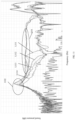
- FIG. 3 is a graph of frequency response curves of acoustic output devices according to some embodiments of the present disclosure.
- the horizontal coordinates represent frequencies (Hz)
- the vertical coordinates represent sound pressures (dB) corresponding to an acoustic output device at different frequencies
- a curve L31 represents a frequency response curve of the acoustic output device 100
- a curve L32 represents a frequency response curve of the acoustic output device 200.
- the vibration of the panel 21 also drives the air on the side of the panel 21 to vibrate to generate the air-conduction sound.
- a vibration force level of the bone conduction sound of the acoustic output device is represented by measuring the sound pressure level of the air-conduction sound near the panel 21.
- a sound sensor e.g., a microphone
- a sound sensor may be provided proximate to the panel 21 to detect a sound pressure level of the air-conduction sound generated by the vibration of the air on the side of the panel 21 driven by the vibration of the panel 21.
- a sound sensor e.g., a microphone
- the determination of the frequency response curve of the acoustic output device in the present disclosure can be achieved by using the above manner.
- the sound pressure of the acoustic output device 200 is overall smaller than the sound pressure of the acoustic output device 100. That is, the sensitivity of the acoustic output device 200 is weaker than the sensitivity of the acoustic output device 100. It can be seen that, when the additional element is disposed on the bone conduction loudspeaker in the acoustic output device, the additional element can affect the sensitivity of the bone conduction loudspeaker. For instance, the sensitivity of the bone conduction loudspeaker is weakened.
- the additional element 40 having a certain mass, which increases the loading mass of the vibration of the transducer device 10.
- the increase of the loading mass of the vibration of the transducer device 10 (at this time, the loading mass of the vibration of the transducer device 10 may at least include the mass of the panel 21, the shell 22, and the additional element 40) can cause the weaken of the sensitivity of the bone conduction loudspeaker, resulting in a relatively low volume of the sound (e.g., the bone conduction sound) output by the acoustic output device 200.
- the additional element may be connected to the panel through a vibration path, and the vibration path may at least include an elastic element.
- the panel, the elastic element, the shell, and the additional element may form a resonance system.
- the resonance system may be in a second resonance position, and the resonance system generates, at the second resonance position, a second resonance frequency that is located within a target frequency range.
- a vibration transmission between the additional element and the panel can be suppressed. That is, the influence of the additional element on the vibration of the panel is reduced, thereby ensuring that the sensitivity of the bone conduction loudspeaker is not or less affected by the additional element in the frequency range greater than the second resonance frequency.
- the frequency range in which the sensitivity of the bone conduction loudspeaker is weakened due to the additional element disposed on the bone conduction loudspeaker may be reduced.
- the frequency response curve of the acoustic output device is flatter due to the smaller influence of the additional element on the vibration of the panel, which can ensure that the acoustic output device has a better acoustic output effect in a wider frequency range, thus improving the user's listening experience.
- the second resonance frequency described above may be generated when the panel and the additional element vibrate in opposite directions and a distance between the panel and the additional element reaches a maximum value.
- a low frequency vibration (below the second resonance frequency) of the panel may be transmitted to the additional element to drive the additional element to vibrate together with the vibration of the panel.
- the mass of the additional element may increase the loading mass of the vibration of the transducer device, which makes the sensitivity of the loudspeaker to be affected by the additional element (similar to the acoustic output device 200) in a frequency range below the second resonance frequency.
- the transducer device When the transducer device generates a high frequency (higher than the second resonance frequency) mechanical vibration, a high frequency vibration of the panel hardly drives the additional element to vibrate together due to the presence of the elastic element.
- the mass of the additional element may not influence the loading mass of the vibration of the transducer device, thus ensuring that the sensitivity of the acoustic output device is not or less affected by the additional element in a frequency range higher than the second resonant frequency.
- the additional element may have a magnetic part (e.g., a part, energized coil, etc., made of magnetic materials, such as metal alloy magnets, ferrite, etc.) or a magnetically conductive part (e.g., a part made of soft magnetic materials such as iron, nickel-iron alloy, etc.), the additional element may be attracted or repelled by the magnetic circuit assembly in the transducer device of the acoustic output device, resulting in the deformation or inversion of the magnetic circuit assembly of the transducer device. Therefore, the stability of the vibration of the transducer device is reduced, resulting in the poor acoustic output effect of the acoustic output device.
- a magnetic part e.g., a part, energized coil, etc., made of magnetic materials, such as metal alloy magnets, ferrite, etc.
- a magnetically conductive part e.g., a part made of soft magnetic materials such as iron, nickel-iron alloy, etc.
- a vibration transmission sheet (also referred to as an elastic support component ) in the transducer device may connect the magnetic circuit assembly to the sidewall of the shell adjacent to the panel. That is, the vibration transmission sheet connects the magnetic circuit assembly and the sidewall of the shell where the additional element is disposed.
- the transducer device may include at least two vibration transmission sheets. One of the at least two vibration transmission sheets may be disposed on a side of the transducer device facing the panel to elastically connect the transducer device and the panel.
- the other one of the least two vibration transmission sheets may be disposed on a side of the transducer device back away from the panel to connect the transducer device to the shell, and support the transducer device to ensure that the transducer device can vibrate stably in an axial direction.
- the vibration transmission sheet disposed on the side of the transducer device back away from the panel may connect the magnetic circuit assembly and the sidewall of the shell where the additional element is disposed, so as to reduce or avoid the problem that the additional element and the magnetic circuit assembly in the transducer device may attract or repel to each other to cause the deformation or inversion of the magnetic circuit assembly.
- the vibration transmission sheet of the transducer device may connect the magnetic circuit assembly to the elastic support component.
- the vibration transmission sheet may provide support in a relative movement direction between the magnetic circuit assembly and the additional element, so that the vibration transmission sheet provides a better support to the magnetic circuit assembly and improves the stability between the magnetic circuit assembly and the shell.
- At least a portion of a connection end of the vibration transmission sheet connecting the sidewall of the shell may be located within an orthographic projection of the additional element on the sidewall of the shell.
- at least one of support rods of the vibration transmission sheet is disposed within the orthographic projection of the additional element on the sidewall of the shell.
- the vibration transmission sheet may include a center region and a plurality of support rods, and the plurality of support rods may be disposed at intervals along a circumferential side of the center region of the vibration transmission sheet.
- the center region of the vibration transmission sheet may be connected to a side of the magnetic circuit assembly away from the panel, and an end of each support rod away from the center region may be connected with the shell.
- the vibration transmission sheet may be connected to the side of the magnetic circuit assembly back away from the panel and may be connected to an intermediate region on the side of the magnetic circuit assembly back away from the panel.
- the intermediate region refers to a geometric center region of the side of the magnetic circuit assembly back away from the panel.
- the center region of the vibration transmission sheet may be connected to the intermediate region on the side of the magnetic circuit assembly back away from the panel.
- a count of support rods may be four.
- a structure of the vibration transmission sheet may be approximately regarded as an "X"-shaped structure.
- the "X"-shaped structure may provide elasticity in the vibration direction of the transducer device.
- the plurality of support rods may have high structural strengths in the vibration direction of the transducer device, which can provide a good support effect on the magnetic circuit assembly to avoid the deformation or inversion of the transducer device during the vibration.
- the vibration transmission sheet may further include an edge region. The edge region may be connected to an end of each support rod away from the center region, and a circumferential side of the edge region may be connected to the shell. More descriptions regarding the structure of the vibration transmission sheet may be found elsewhere in the present disclosure (e.g., FIGs. 46 and 47 , and relevant descriptions thereof).
- FIG. 4-FIG. 32 The acoustic output device according to some embodiments of the present disclosure may be described in detail below in combination with the accompanying drawings ( FIG. 4-FIG. 32 ).
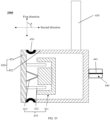
- FIG. 4 is a schematic diagram illustrating an exemplary structure of an acoustic output device 400 according to some embodiments of the present disclosure.
- Structures of a transducer device 410 including a magnetic circuit assembly 411, a coil 412, a vibration transmission sheet 413A), a housing 420 (including a panel 421, a shell 422), a support structure 430, etc., in the acoustic output device 400 shown in FIG. 4 may be similar to the transducer device 10 (including the magnetic circuit assembly 11, the coil 12, the vibration transmission sheet 13), the housing 20 (including the panel 21, the shell 22), the support structure 30, etc., in the acoustic output device 200 shown in FIG. 2 , respectively, which are not be further described herein.
- the main difference between the acoustic output device 400 shown in FIG. 4 and the acoustic output device 200 shown in FIG. 2 may include that an additional element 440 is connected to the panel 421 through a vibration path including an elastic element 450.
- the panel 421 is elastically connected to the shell 422 through the elastic element 450. That is, the panel 421 (and structure(s) rigidly connected to the panel 421 (e.g., the coil 412 )), the elastic element 450, and the shell 422 (and structure(s) rigidly connected to the shell 422 (e.g., the additional element 400 and the support structure 430)) form a resonance system.
- the connection of the panel 421 and the shell 422 may be approximately regarded as a rigid connection
- the transducer device may drive the panel 421 to vibrate
- the panel 421 may drive the shell 422 and the additional element 440 to vibrate together through the elastic element 45.
- the acoustic output device having the additional element 440 may have a relatively weak sensitivity.
- a relatively high frequency band e.g., a frequency band range greater than 20 Hz
- the panel 421, the elastic element 450, and the shell 422 may be approximately regarded as a resonance system.
- the transducer device may drive the panel 421 to vibrate, and under the action of the elastic element 450, a relative motion may occur between the panel 421 and the shell 422 (and component(s) (e.g., the additional element 440) rigidly connected to the shell 422.
- the vibration of the panel 421 is at a minimum value (e.g., the panel 421 vibrates relatively little or not at all), and the shell 422 and the additional element 440 vibrate strongly.
- This time may be considered as a first resonance position of the resonance system, and a resonance frequency when the resonance system is located at this first resonance position may be a first resonance frequency.
- a frequency response curve of the acoustic output device 400 may have a resonance valley at the first resonance frequency. It can be understandable that, in the resonance system of some other embodiments, the frequency response curve of the acoustic output device 400 may not have a distinct resonance valley at the first resonance frequency.
- the panel 421, the shell 422, and the additional element 440 rigidly connected to the shell 422 may vibrate strongly until the panel 421 and the shell 422 (and the additional element 440 rigidly connected to the shell 422) vibrate in the opposite directions and a distance between the panel 421 and the shell 422 reaches a maximum value.
- This time may be regarded as a second resonance position of the resonance system, and the resonance frequency when the resonance system is located at the second resonance position may be a second resonance frequency.
- the frequency response curve of the acoustic output device 400 may have a resonance peak at the second resonance frequency.
- the frequency response curve of the acoustic output device 400 may not have a distinct resonance peak at the second resonance frequency.
- the panel 421 and the shell 422 (and the additional element 440 rigidly connected to the shell 422) may vibrate in the opposite directions.
- the vibration transmission between the shell 422 (and the additional element 440) and the panel 421 may be suppressed. That is, the effect of the shell 422 and the additional element 440 on the vibration of the panel 421 is reduced.
- the panel 421 and the shell 422 From a phase of the resonance system, the panel 421 and the shell 422 first move together. At this time, the panel 421 and the shell 422 (and the additional element 440 connected to the shell 422) may vibrate together, and a phase difference between the panel 421 and the shell 422 may be 0 degrees. As the frequency increases, the panel 421 and the shell 422 (and the additional element 440) may first move along a same direction until the panel 421 vibrates little or stops vibration, and the shell 422 and the additional element 440 vibrate relatively strongly, i.e., the first resonance position.
- a value corresponding to the phase of the resonance system may increase, and the panel 421, the shell 422, and the additional element 440 rigidly connected to the shell 422 all vibrate strongly until the panel 421 and the shell 422 (and the additional element 440) vibrate in the opposite directions and the distance between the panel 421 and the shell 422 (and the additional element 440) reaches the maximum value, i.e., the second resonance position.
- the phase difference between the panel 421 and the shell 422 may be within a range of 150 degrees to 210 degrees, and the resonance system may be located at the second resonance position. Then, as the frequency continues to increase, the value corresponding to the phase of the resonance system progressively may decrease.
- the panel 421 and the shell 422 having the additional element 440 may be connected through the elastic element 450, so that the panel 421 and the shell 422 having the additional element 440 can be resonate and generate the second resonance frequency within a target frequency range.
- the vibration transmission between the additional element 440 and the panel 421 may be suppressed. That is, the effect of the additional element 440 on the vibration of the panel 421 can be reduced, thereby ensuring that the sensitivity of the bone conduction loudspeaker in the acoustic output device is not or less affected by the additional element 440 in the frequency range greater than the second resonance frequency.
- a frequency range in which the sensitivity of the bone conduction loudspeaker in the acoustic output device is weakened due to the additional element 440 being disposed on the acoustic output device may be reduced.
- the frequency response curve of the acoustic output device may be flatter due to the smaller influence of the additional element 440 on the vibration of the panel 421, which ensures that the acoustic output device has a better acoustic output effect in a larger frequency range, improving the user's listening experience.
- the panel 421 and the structure(s) rigidly connected to the panel 421 may form the resonance system.
- the shell 422 may be a structure that is internally hollow and has an open opening at one end, and the panel 421 may be disposed at the end of the shell 422 that has the open opening.
- the elastic element 450 may be disposed between the panel 421 and the shell 422 to realize an elastic connection between the panel 421 and the shell 422.
- the elastic element 450 herein may also be considered as a portion of the housing 420 in the acoustic output device 400.
- the panel 421, the shell 422, and the elastic element 450 may form an accommodating chamber for accommodating the transducer device 10.
- the elastic element 450 may be a ring structure with elasticity.
- the panel 421 may be elastically connected to the shell 422 through the ring structure, so as to form the accommodating chamber for accommodating the transducer device 410.
- the elastic element 450 may be the ring structure made of an elastic material, such as silicone, polyurethane, etc.
- the ring structure may be a single ring structure or a structure including a plurality of folded rings with a pre-deformation capability. When the panel 421 is connected to the shell 422 through the ring structure, the ring structure with the pre-deformation capability may support the panel 421 and the shell 422 to a certain extent, improving the structural stability of the acoustic output device.
- the panel 421 and the shell 422 may be elastically connected through adhering.
- the adhesive used to adhere the panel 421 and the shell 422 may have elasticity, which may be regarded as the elastic element 450.
- the adhesive used to adhere the panel 421 and the shell 422 may include a gel type, an organic-silicone type, an acrylic type, a polyurethane type, a rubber type, an epoxy type, a hot melt type, a light curing type, or the like, or any combination thereof.
- the adhesive may be a silicone adhering type glue, a silicone sealing type glue.
- the additional element 440 may be rigidly connected to the shell 422 directly or indirectly.
- the additional element 440 may be rigidly connected to a sidewall of the shell 422 (e.g., a sidewall on the shell 422 adjacent to the panel 421 or a sidewall on the shell 422 opposite to the panel 421) by welding, snap-fitting, threading, adhesive connection, etc.
- the additional element 440 may be rigidly connected to the shell 422 through a connection such as a bracket, a connecting rod, etc.
- the additional element 440 shown in FIG. 4 may include an element (e.g., a loudspeaker, an air-conduction microphone, an accelerometer) that is sensitive to the vibration direction. In the embodiment shown in FIG.
- the additional element 440 may be an air-conduction microphone that is sensitive to the vibration direction.
- a vibration direction (a "second direction” shown in FIG. 4 ) of a diaphragm 441 of the air-conduction microphone may be approximately perpendicular to a vibration direction (a "first direction” shown in FIG. 4 ) of the transducer device 410.
- the approximately perpendicular can be understood as that an included angle between the vibration direction of the diaphragm and the vibration direction of the transducer device is within a range of 75 degrees to 100 degrees, for example, 80 degrees, 90 degrees, 95 degrees, etc.
- the diaphragm may generate the vibration during an operation of the air-conduction loudspeaker.
- the additional element 440 may not be limited to the element that is sensitive to the vibration direction shown in FIG. 4 , but may also be a battery, a circuit board, or a sensor (e.g., a temperature sensor, a humidity sensor, etc.) that is not sensitive to the vibration direction.
- the additional element may be located at an arbitrary position on the shell 422.
- the additional element 440 may include an element that is sensitive to the vibration direction and an element that is insensitive to the vibration direction.
- the element that is sensitive to the vibration direction is an accelerometer sensor
- the element that is insensitive to the vibration direction is a circuit board.
- the circuit board may be fixedly connected to the shell 422, and the accelerometer sensor may be disposed on the circuit board.
- the panel 421 (and the structure(s) (e.g., the coil 412) rigidly connected to the panel 421) and the shell 422 (and the structure(s) (e.g., the additional element 440) rigidly connected to the shell 422) may be elastically connected to each other through the elastic element 450, which can be approximately regarded as a resonance system.
- the resonance system may be located at the second resonance position, and generate the second resonance frequency whose resonant frequency is within a target frequency range. In the frequency range greater than the resonance frequency corresponding to the second resonance frequency, the vibration transmission between the additional element 440 and the panel may be suppressed.
- the influence of the additional element 440 on the vibration of the panel 421 may be reduced, so that the sensitivity of the acoustic output device 400 is not or less affected by the additional element 440 in the frequency range that is greater than the resonance frequency corresponding to the second resonance frequency.
- the resonance frequency corresponding to the second resonance frequency at a relatively low frequency position, the frequency range in which the sensitivity of the acoustic output device 400 is weakened due to the additional element 440 can be reduced.
- the frequency response curve of the acoustic output device 400 is flatter due to the smaller influence of the additional element 440 on the vibration of the panel 421, which can ensure that the acoustic output device has a better acoustic output effect in a wider frequency range, improving the user's listening experience.
- a ratio of a sum of the mass of the panel 421 and the mass of the element(s) rigidly connected to the panel 421 to a sum of the mass of the shell 422 and the mass of the element(s) fixedly connected to the shell 422, an elastic coefficient of the elastic element 450, etc. may be adjusted, so that the resonance frequency corresponding to the second resonance frequency is located within a specific low frequency range (also referred to as a target frequency range).
- the target frequency range may be within a range of 20 Hz to 800 Hz.
- the target frequency range may be within a range of 100 Hz to 600 Hz.
- the target frequency range may be within a range of 150 Hz to 500 Hz.
- the target frequency range may be within a range of 200 Hz to 400 Hz. More descriptions regarding the adjusting the resonance frequency may be found elsewhere in the present disclosure (e.g., FIG. 6 and relevant descriptions thereof).
- the acoustic output device 400 may also generate the first resonance frequency whose resonance frequency is within the target frequency range. In some embodiments, the first resonance frequency may be less than the second resonance frequency.
- a difference between the frequency corresponding to the second resonance frequency and the frequency corresponding to the first resonance frequency may not be greater than 300 Hz.
- the difference between the frequency corresponding to the second resonant frequency and the frequency corresponding to the first resonant frequency may not be greater than 200 Hz.
- the difference between the frequency corresponding to the second resonance frequency and the frequency corresponding to the first resonance frequency may not be greater than 100 Hz.
- FIG. 5 is a graph of frequency response curves of acoustic output devices according to some embodiments of the present disclosure.
- FIG. 5 shows frequency response curves of the acoustic output device 100 and the acoustic output device 400.
- the horizontal coordinates represent frequencies (Hz)
- the vertical coordinates represent sound pressures (dB) corresponding to an acoustic output device at different frequencies
- a curve L51 represents a frequency response curve of the acoustic output device 100
- a curve L52 represents a frequency response curve of the acoustic output device 400
- a curve L53 represents a frequency response curve of the acoustic output device 400 after adding damping.
- FIG. 5 shows frequency response curves of the acoustic output device 100 and the acoustic output device 400.
- the horizontal coordinates represent frequencies (Hz)
- the vertical coordinates represent sound pressures (dB) corresponding to an acoustic output device at different frequencies
- a curve L51 represents a
- the frequency response curve of the acoustic output device 400 has a resonance valley at a first resonance frequency
- the frequency response curve of the acoustic output device 400 has a second resonance frequency with a resonance peak.
- the embodiment in which the frequency response curve of the acoustic output device has a distinct resonance valley at the first resonance frequency and has a distinct resonance peak at the second resonance frequency is merely for illustration. It can be understandable that, the frequency response curve of the acoustic output device in the present disclosure may also have no distinct resonance valley at the first resonance frequency and no distinct resonance peak at the second resonance frequency.
- the resonance peaks in a region A are generated by the resonance system when the distance between the panel 421 and the shell 422 reaches a maximum value
- the resonance valleys in a region B are generated by the resonance system when the panel 421 does not vibrate or the vibration of the panel 421 is at a minimum value and the shell 422 vibrates.
- the acoustic output device 400 generates the resonance peak and the resonance valley in a frequency range of 200 Hz to 600 Hz.
- the resonance peak is generated when the panel 421 and the additional element 440 vibrate in opposite directions and the distance between the panel 421 and the additional element 440 reaches the maximum value, and the resonance valley is generated when the panel 421 does not vibrate or the vibration of the panel 421 is at the minimum value and the shell 422 vibrates.
- the sensitivity of the acoustic output device 100 disposed with no additional element in FIG. 3 is overall stronger than the sensitivity of the acoustic output device 200 disposed with the additional element in a frequency range of 200 Hz to 8000 Hz.
- the frequency response curves of the acoustic output device 400 and the acoustic output device 100 approximately overlap in a frequency range greater than the resonance frequency.
- the acoustic output device 400 (the additional element 440 is connected to the panel 421 through a vibration path including the elastic element 450) has a relatively strong sensitivity in a specific frequency band (e.g., a frequency range greater than the resonance frequency corresponding to the resonance peak A) as compared to the acoustic output device 200 shown in FIG. 2 (the panel 21 is rigidly connected to the shell 22 disposed with the additional element 40).
- the curves L51, L52, and L53 substantially overlap and are relatively flat in the frequency range greater than the resonance frequency corresponding to the resonance peak. It can be seen, the frequency response curve of the acoustic output device 400 is flatter when the frequency is greater than the resonance frequency corresponding to the resonance peak, and the additional element 440 (e.g., an air-conduction loudspeaker, a sensor, a battery, a circuit board, etc.) in the acoustic output device 400 do not affect the sensitivity of the speaker 400 in the frequency range higher than the resonance frequency corresponding to the resonance peak.
- the additional element 440 e.g., an air-conduction loudspeaker, a sensor, a battery, a circuit board, etc.
- the resonance frequency corresponding to the resonance peak may be located within a specific frequency range (e.g., less than 2000 Hz, less than 1500 Hz, less than 800 Hz, less than 600 Hz, etc.). More descriptions regarding the adjusting the resonance frequency may be found elsewhere in the present disclosure (e.g., FIG. 6 and relevant descriptions thereof).
- a damping material may be disposed in the elastic element 450 to increase the damping of the acoustic output device 400.
- the damping material may include butyl, acrylate, polysulfide, nitrile and silicone rubbers, urethanes, polyvinyl chloride, epoxies, or the like, or any combination thereof.
- FIG. 6 is a graph of frequency response curves of acoustic output devices according to some embodiments of the present disclosure.
- FIG. 6 shows frequency response curves of the acoustic output device 400 when ratios of the mass of the panel 421 to a sum of the mass of the shell 422 and the mass of the additional element 440 are different.
- the horizontal coordinates represent frequencies (Hz), and the vertical coordinates represent sound pressures (dB) corresponding to an acoustic output device at different frequencies.
- a curve L61 represents a frequency response curve of the acoustic output device 400 when a ratio of a sum of the mass of the panel 421 and the mass of element(s) (e.g., the coil 412) rigidly connected to the panel 421 to the sum of the mass of the shell 422 and the mass of element(s) (e.g., the additional element 440) rigidly connected to the shell 422 is 0.16 and an elasticity coefficient is 588 Newton per meter (N/m).
- the curve L62 represents a frequency response curve of the acoustic output device 400 when the ratio of the sum of the mass of the panel 421 and the mass of the element(s) rigidly connected to the panel 421 to the sum of the mass of the shell 422 and the mass of the element(s) rigidly connected to the shell 422 is 0.36 and the elasticity coefficient is 2000 N/m.
- the curve L63 represents a frequency response curve of the acoustic output device 400 when the ratio of the sum of the mass of the panel 421 and the mass of the element(s) rigidly connected to the panel 421 to the sum of the mass of the shell 422 and the mass of the element(s) rigidly connected to the shell 422 is 1.03.
- the curve L64 represents a frequency response curve of the acoustic output device 400 when the ratio of the sum of the mass of the panel 421 and the mass of the element(s) rigidly connected to the panel 421 to the sum of the mass of the shell 422 and the mass of the element(s) rigidly connected to the shell 422 is 3.07.
- the curve L65 represents a frequency response curve of the acoustic output device 400 when the ratio of the sum of the mass of the panel 421 and the mass of the element(s) rigidly connected to the panel 421 to the sum of the mass of the shell 422 and the mass of the element(s) rigidly connected to the shell 422 is 5.14.
- the resonance peaks in a region C are resonance peaks generated during vibrations of the resonance system formed by the panel 421, the additional element 440, and the elastic element 450.
- the resonance valleys in a region D are resonance valleys generated during the vibrations of the resonance system formed by the panel 421, the additional element 440, and the elastic element 450.
- the frequency response curves of the acoustic output device 400 are flatter in a frequency range higher than the resonance frequency corresponding to the resonance peak, which enables the acoustic output device 400 to output a better sound quality in the frequency range higher than the resonance frequency corresponding to the resonance peak.
- the frequency corresponding to the resonance valley may be consequently increased, the difference between the frequency corresponding to the resonance valley and the frequency corresponding to the resonance peak may be reduced, the difference between the resonance valley and the resonance peak may be reduced, the influence of the additional element 440 on the frequency response of the acoustic output device 400 may be reduced, the frequency response curve of the acoustic output device 400 may be flatter, and the sound quality of the acoustic output device 400 may be better.
- the influence of the additional element on the frequency response of the acoustic output device 400 can be reduced by adjusting the ratio of the sum of the mass of the panel 421 and the mass of the element(s) rigidly connected to the panel 421 to the sum of the mass of the shell 422 and the mass of the element(s) rigidly connected to the shell 422.
- the ratio of the sum of the mass of the panel 421 and the mass of the element(s) rigidly connected to the panel 421 to the sum of the mass of the shell 422 and the mass of the element(s) rigidly connected to the shell 422 may be within a range of 0.16 to 7.
- the ratio of the sum of the mass of the panel 421 and the mass of the element(s) rigidly connected to the panel 421 to the sum of the mass of the shell 422 and the mass of the element(s) rigidly connected to the shell 422 may be within a range of 0.36 to 6. In some embodiments, the ratio of the sum of the mass of the panel 421 and the mass of the element(s) rigidly connected to the panel 421 to the sum of the mass of the shell 422 and the mass of the element(s) rigidly connected to the shell 422 may be within a range of 1.03 to 5.14.
- the ratio of the sum of the mass of the panel 421 and the mass of the element(s) rigidly connected to the panel 421 to the sum of the mass of the shell 422 and the mass of the element(s) rigidly connected to the shell 422 may be within a range of 1.03 to 3.07.
- the acoustic output device 400 may also include a support structure 430.
- the support structure 430 may be rigidly connected to the shell 422.
- the support structure 430 may be rigidly connected to a sidewall of the shell 422 opposite to the panel 421.
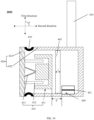
- FIG. 7 is a schematic diagram illustrating an exemplary structure of an acoustic output device 700 according to some embodiments of the present disclosure. As shown in FIG. 7 , the support structure 430 in the acoustic output device 700 may be rigidly connected to the panel 421.
- the connection between the support structure 430 and the panel 421 or the shell 422 has less influence on the frequency response of the acoustic output device.
- the support structure 430 may be an ear hook.
- the ear hook is typically made of a flexible material, and has a better ability to undergo elastic deformation.
- the support structure 430 typically affects the vibration of the bone conduction loudspeaker in a relatively low frequency band (e.g., near and below 20 Hz), and the frequency band is typically inaudible to the human ear. More descriptions may be found in FIG. 8 and relevant descriptions thereof.
- FIG. 8 is a graph of frequency response curves of acoustic output devices according to some embodiments of the present disclosure.
- FIG. 8 shows the frequency response curves of the acoustic output device 400 and an acoustic output device 700.
- the horizontal coordinates represent frequencies (Hz), and the vertical coordinates represent sound pressures (dB) corresponding to an acoustic output device at different frequencies.
- a curve L71 represents a frequency response curve of the acoustic output device 400 when the support structure 430 is rigidly connected to the shell 422, and a curve L72 represents a frequency response curve of the acoustic output device 700 when the support structure 430 is rigidly connected to the panel 421.
- the support structure 430 being rigidly connected to the panel 421 or being rigidly connected to the shell 422 has little influence on the frequency response of the acoustic output device 400 or 700.
- the support structure 430 may be rigidly connected to the panel 421 or rigidly connected to the shell 422.
- the connection between the magnetic circuit assembly 411 and the panel 421 through the vibration transmission sheet 413A may cause the problem that the additional element and the magnetic circuit assembly in the transducer device may attract or repel to each other to cause the deformation or inversion of the magnetic circuit assembly, thereby affecting the vibration stability of the transducer device 410.
- the vibration transmission sheet 413A between the magnetic circuit assembly 411 and the panel 421 may be replaced with a vibration transmission sheet 413B (indicated by dashed lines in FIGs. 4 and 7 ).
- the vibration transmission sheet 413B may be disposed between the magnetic circuit assembly 411 and a sidewall of the shell 422 opposite to the panel 421.
- a side of the vibration transmission sheet 413B may be connected to a side of the magnetic circuit assembly 411 back away from the panel 421, and a circumferential side of the vibration transmission sheet 413B may be connected to a sidewall of the shell 422 adjacent to the panel 421.
- the vibration transducer 413B can enhance the support effect of the magnetic circuit assembly 411 on a position near the additional element 440 and improve the vibration stability of the transducer device (especially the magnetic circuit assembly 411).
- the acoustic output device 400 or 700 may include both the vibration transmission sheet 413A and the vibration transmission sheet 413B.
- FIG. 9 is a schematic diagram illustrating an exemplary structure of an acoustic output device 900 according to some embodiments of the present disclosure.
- Structures of a transducer device 910 including a magnetic circuit assembly 911, a coil 912, a vibration transmission sheet 913A, a vibration transmission sheet 913B), a housing 920 (including a panel 921), a support structure 930, an additional element 940, an elastic element 950, etc., illustrated in FIG.
- the shell 922 includes one or more pressure relief holes 9221 configured to connect air inside and outside the housing 920.
- the pressure relief holes 9221 may be opened in a sidewall of the shell 922 opposite and/or adjacent to the panel 921.
- the pressure relief holes 9221 may also be disposed at the elastic element 950.
- the elastic element 950 may also be a reed with through holes or an elastic web, and the through holes or slits in the elastic web may replace the pressure relief holes 9221 to connect the air inside and outside shell 922.
- pressure relief holes 9221 herein may also be applied in the acoustic output devices according to other embodiments of the present disclosure, such as acoustic output devices 300, 400, 700, 1200, 1300, 1500, 1700, 1800, 1900, 2000, 2200, 2400, 2500, 2600, 2700, 2900, 3000, 3100, etc.
- the magnetic circuit assembly 911 may be connected to the panel 921 through the vibration transmission sheet 913A, which causes the problem that the magnetic circuit assembly 911 and the additional element 940 may attract or repel to each other to cause the deformation or inversion of the magnetic circuit assembly 911, thereby affecting the vibration stability of the transducer device 910.
- the vibration transmission sheet 913A between the magnetic circuit assembly 911 and the panel 921 may be replaced with the vibration transmission sheet 913B (indicated by dashed lines in FIG. 9 ).
- the vibration transmission sheet 913B may be disposed between the magnetic circuit assembly 911 and the sidewall on the shell 922 opposite to the panel 921.
- a side of the vibration transmission sheet 913B may be connected to a side of the magnetic circuit assembly 911 back away from the panel 921, and a circumferential side of the vibration transmission sheet 913B may be connected to a sidewall of the shell 922 adjacent to the panel 921.
- the vibration transmission sheet 913B can enhance the support effect of the magnetic circuit assembly 911 on a position near the additional element 940, and improve the vibration stability of the transducer device 910 (especially the magnetic circuit assembly 911).
- the acoustic output device 900 may include the vibration transmission sheet 913A and the vibration transmission sheet 913B.
- FIG. 10 is a graph of frequency response curves of acoustic output devices according to some embodiments of the present disclosure.
- FIG. 10 shows the frequency response curves of the acoustic output device 700 and the acoustic output device 900.
- the horizontal coordinates represent frequencies (Hz), and the vertical coordinates represent sound pressures (dB) corresponding to an acoustic output device at different frequencies.
- a curve L101 represents a frequency response curve of the acoustic output device 700, and the curve L101 includes a resonance peak 1011.
- a curve L102 represents a frequency response curve of the acoustic output device 900, and the curve L102 includes a resonance peak 1021.
- a resonance frequency corresponding to the resonance peak 1011 is higher than a resonance frequency corresponding to the resonance peak 1021, and a frequency range (i.e., a frequency range greater than the resonance frequency corresponding to the resonance peak 1021) in which the sensitivity of the acoustic output device 900 is not or less affected by the additional element is wider than a frequency range (i.e., a frequency range greater than the resonance frequency corresponding to the resonance peak 1011) in which the sensitivity of the acoustic output device 700 is not or less affected by the additional element.
- the resonance frequency corresponding to a resonance peak generated by the additional element that is driven by the elastic element to vibrate with respect to the panel can be reduced, so as to broaden the frequency range in which the sensitivity of the acoustic output device is not or less affected by the additional element.
- sound leakage may be generated by the vibration of the outside air driven by the vibration of the shell and/or the panel.
- the pressure relief holes disposed on the shell of the acoustic output device can also reduce a volume of the sound leakage of the acoustic output device.
- the pressure relief holes may export sound generated by the vibration of the magnetic circuit assembly inside the accommodating chamber to the outside world, and the sound may offset the sound leakage generated by the vibration of the shell and/or the panel, thereby reducing the volume of the sound leakage of the acoustic output device.
- the mass of the additional element may be adjusted to reduce the volume of the sound leakage of the acoustic output device in a frequency range higher than the resonance frequency corresponding to the resonance peak.
- FIG. 11 is a graph of frequency response curves of an acoustic output device according to some embodiments of the present disclosure.
- FIG. 11 illustrates sound leakage frequency response curves of the back panel (i.e., the sidewall of the shell 922 opposite to the panel 921) of the acoustic output device 900 and frequency response curves of the panel 921 of the acoustic output device 900 when the additional element have different masses.
- a curve L111 represents a sound leakage frequency response curve of the acoustic output device 900 when the mass of the additional element is 0 grams (g).
- the curve L112 represents a sound leakage frequency response curve of the acoustic output device 900 when the mass of the additional element is 0.7 g.
- the curve L113 represents a sound leakage frequency response curve of the acoustic output device 900 when the mass of the additional element is 1.4 g.
- the curve L114 represents a sound leakage frequency response curve of the acoustic output device 900 when the mass of the additional element is 2.1 g.
- a region 1101 represents frequency response curves of the acoustic output device 900 having the additional element with different masses.
- a region 1102 represents a resonance peak region of the acoustic output device 900 having the additional element with different masses.
- the sound leakage frequency response curves of the acoustic output device 900 may be measured by collecting air-conduction sound on the sidewall of the shell 922 opposite to the panel 921, and the frequency response curves of the acoustic output device 900 may be measured by collecting air-conduction sound on the panel 921. As shown in FIG.
- the region 1101 and the region 1102 shows that the acoustic output device 900 has essentially the same sensitivity when the acoustic output device 900 has the additional element with different masses in a frequency range (including the frequency range corresponding to the region 1101) higher than the resonance frequency corresponding to the resonance peak region (the region 1102). That is, the sensitivity of the acoustic output device 900 does not weaken with an increase of the mass of the additional element.
- the resonance frequency corresponding to the resonance peak in the leakage sound response curve of the acoustic output device 900 may reduce.
- the mass of the additional element may be adjusted, such that the resonance frequency corresponding to the resonance peak in the sound leakage frequency response curve of the acoustic output device is less than the resonance frequency corresponding to the resonance peak in the frequency response curve of the acoustic output device. Therefore, the acoustic output device 900 in a frequency range (e.g., 300 Hz to 8000 Hz) where the sensitivity of the acoustic output device is not affected by the mass of the additional element can generate a relatively small volume of the sound leakage. In some embodiments, the resonance frequency corresponding to the resonance peak in the sound leakage frequency response curve of the acoustic output device may not be greater than 700 Hz.
- the resonance frequency corresponding to the resonance peak in the sound leakage frequency response curve of the acoustic output device may not be greater than 500 Hz.
- the resonance frequency corresponding to the resonance peak in the sound leakage frequency response curve of the acoustic output device may not be greater than 300 Hz.
- the resonance frequency corresponding to the resonance peak in the sound leakage frequency response curve of the acoustic output device may not be greater than 200 Hz.
- the pressure relief holes and the scheme of adjusting the mass of the additional element are not only applicable to the acoustic output device 900, but also to other acoustic output devices according to some embodiments of the present disclosure (e.g., the acoustic output devices 400, 700, 1200, etc.).
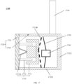
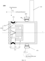
- FIG. 12 is a schematic diagram illustrating an exemplary structure of an acoustic output device 1200 according to some embodiments of the present disclosure.
- a transducer device 1210 (including a magnetic circuit assembly 1211, a coil 1212, a vibration transmission sheet 1213A, a vibration transmission sheet 1213B), a housing 1220 (including a panel 1221), a support structure 1230, and an additional element 1240 in the acoustic output device 1200 shown in FIG.
- the transducer device 410 including the magnetic circuit assembly 411, the coil 412, the vibration transmission sheet 413A, and the vibration transmission sheet 413B), the housing 420 (including the panel 421), the support structure 430, and the additional element 440 in the acoustic output device 700, respectively, which are not be further described herein.
- the main difference between the acoustic output device 1200 and the acoustic output device 700 may include that a sidewall (also referred to as a back panel 12221) of the shell 1222 of the acoustic output device 1200 opposite to the panel 1221 is connected to other sidewalls of the shell 1222 (sidewalls adjacent to the panel 1221, also referred to as a housing body 12222) through an elastic element 1260.
- the elastic element 1260 may be a ring structure as shown in FIG. 12 , and the ring structure may be made of an elastomeric material.
- the shell 1222 may include the housing body 12222 and the back panel 12221.
- the housing body 12222 includes the panels on the shell 1222 adjacent to the panel 1221, and the back panel 12221 is the sidewall of the shell 1222 opposite to the panel 1221.
- the back panel 1221 is independently disposed with respect to the housing body 12222, the ring structure is disposed around a circumferential side of the back panel 12221, and the circumferential side of the ring structure is connected to a sidewall of the housing body 12222.
- the structure of the elastic element 1260 illustrated in FIG. 12 is merely for illustration, and is not intended to limit the scope of the present disclosure.
- the elastic element 1260 may also be a structure having other shapes (e.g., a strip, a sheet, a plate, etc.) made of an elastic material.
- the elastic material may include polycarbonate (PC), polyamides (PA), acrylonitrile butadiene styrene (ABS), polystyrene (PS), high impact polystyrene (HIPS), polypropylene (PP), polyethylene terephthalate (PET), polyvinyl chloride (PVC), polyurethanes (PU), polyethylene (PE), phenol formaldehyde (PF), urea-formaldehyde (UF), melamine-formaldehyde (MF), polyarylate (PAR), polyetherimide (PEI), pcolyimide (PI), polyethylene naphthalate two formic acid glycol ester (PEN), polyetheretherketone (PEEK), carbon fiber, graphene, silica gel, or the like, or any combination thereof.
- PC polycarbonate
- PA polyamides
- ABS acrylonitrile butadiene styrene
- PS high impact polystyrene
- HIPS polyprop
- the elastic element 1260 may be an elastic structural body.
- the elastic structural body refers to a structure that is inherently elastic. That is, even though the material is hard, the elastic element 1260 is inherently elastic since the structure is inherently elastic.
- the elastic structure may include a structure such as a reed structure. That is, the elastic element 1260 may be the reed structure.
- the elastic element 1260 may also be a glue with a certain elasticity used to adhere the housing body 12222 and the back panel 12221.
- the glue having a certain elasticity may be a silicone bonding type of glue, a silicone glue, etc.
- the housing body 12222 may be in a sealed connection with the back panel 12221.
- the connection between the housing body 12222 and the back panel 12221 may also not be a sealed connection, and a gap between the housing body 12222 and the back panel 12221 may act as a pressure relief hole, connecting the air inside and outside the shell 1222 to reduce the resonance frequency corresponding to the resonance peak of the acoustic output device 1200.
- the frequency range in which the sensitivity of the acoustic output device 1200 is not affected by the additional element can be wider.
- the back panel 12221 of the acoustic output device 1200 may be connected to the housing body 12222 through the elastic element 1260, and the back panel 12221 and the elastic element 1260 may be equivalent to a mass-elastic module.
- the mass-elastic module may have an vibration isolation effect, so that the high frequency vibration generated by the transducer device 1210 cannot be transmitted to the back panel 12221. Therefore, the high frequency vibration of the back panel 12221 that generates the high frequency sound leakage can be avoided.
- the back panel and the housing body in other acoustic output devices may also be connected through the elastic element, so as to avoid the acoustic output device from generating the high frequency sound leakage on the side of the back panel.
- the magnetic circuit assembly 1211 may be connected to the panel 1221 by the vibration transmission sheet 1213A, which causes the problem that the magnetic circuit assembly 1211 and the additional element 1240 may attract or repel to each other to cause the deformation or inversion of the magnetic circuit assembly 1211, thereby affecting the vibration stability of the transducer device 1210.
- the vibration transmission sheet 1213A between the magnetic circuit assembly 1211 and the panel 1221 may be replaced with the vibration transmission sheet 1213B (indicated by dashed lines in FIG. 12 ).
- the vibration transmission sheet 1213B may be disposed between the magnetic circuit assembly 1211 and the sidewall on the shell 1222 opposite to the panel 1221.
- a side of the vibration transmission sheet 1213B may be connected to a side of the magnetic circuit assembly 1211 back away from the panel 1221, and a circumferential side of the vibration transmission sheet 1213B may be connected to a sidewall (the housing body 12222) of the shell 1222 adjacent to the panel 1221.
- the vibration transmission sheet 1213B can enhance the support effect of the magnetic circuit assembly 1211 on a position near the additional element 1240, and improve the vibration stability of the transducer device 1210 (especially the magnetic circuit assembly 1211).
- the acoustic output device 1200 may include the vibration transmission sheet 1213A and the vibration transmission sheet 1213B.
- the magnetic circuit assembly 1211 may include an aperture portion 12111 and a positioning rod 12112.
- the aperture portion 12111 may penetrate the magnetic circuit assembly 1211 in a vibration direction of the transducer device 1210 (a first direction shown in FIG. 12 ).
- An end of the positioning rod 12112 away from the panel 1221 may be connected to the back panel 12221, and another end of the positioning rod 12112 may pass through the aperture portion 12111 and connected to the panel 1221.
- the another end of the positioning rod 12112 may be connected to the panel 1221, so that the panel 1221 vibrates together with the back panel 12221, reducing sound leakage due to unsynchronized vibrations between the panel 1221 and the back panel 12221.
- the cooperation between the positioning rod 12112 and the aperture portion 12111 may further increase the stability of the magnetic circuit assembly 1211, reducing the risk that the magnetic circuit assembly 1211 and the additional element 1240 attract or repel to each other to cause the deformation or inversion of the magnetic circuit assembly 1211.
- the magnetic circuit assembly including the aperture portion 12111 and the positioning rod 12112 is applicable to other acoustic output devices in the embodiments of the present disclosure, e.g., the acoustic output device 400 illustrated in FIG.4 , the acoustic output device 700 illustrated in FIG.9 , the acoustic output device 900 illustrated in FIG.13 , an acoustic output device 1500 illustrated in FIG.15 , etc.
- FIG. 13 is a schematic diagram illustrating an exemplary structure of an acoustic output device 1300 according to some embodiments of the present disclosure.
- the acoustic output device 1300 may include a transducer device 1310, a housing 1320, a support structure 1330, an additional element 1340, and an elastic element 1350.
- the transducer device 1310 may include a magnetic circuit assembly 1311, a coil 1312, a vibration transmission sheet 1313A, and a vibration plate 1314.
- the vibration plate 1314 may be elastically connected to the magnetic circuit assembly 1311 through the vibration transmission sheet 1313A.
- the housing 1320 may include a panel 1321 and a shell 1322.
- the shell 1322 may include a back panel 13221opposite to the panel 1321 and a housing body 13222 adjacent to the panel 1321.
- the support structure 1330 may be rigidly connected to the panel 1321 or the shell 1322 (e.g., the back panel 13221 and the housing body 13222).
- the elastic element 1350 may be a vibration damping sheet.
- the panel 1321 may be elastically connected to the shell 1322 through the vibration damping sheet.
- the additional element 1340 may be rigidly connected to the shell 1322, the panel 1321 may be rigidly connected to the vibration plate 1314, and the shell 1322 may be connected to the vibration plate 1314 and the panel 1321 through the vibration damping sheet.
- the vibration plate 1314 may be connected to the coil 1312.
- the coil 1312 may drive the vibration plate 1314 together with the panel 1321 to perform a mechanical vibration.
- the vibration plate 1314 may be rigidly connected to the panel 1321 through a rigid member (e.g., a connecting rod).
- the rigid member may be connected to the shell 1322 (the sidewall of the shell 1322 adjacent to the panel 1321) through the vibration damping sheet, thereby connecting the shell 1322 and the vibration plate 1314 with the panel 1321.
- the panel 1321 (and structure(s) (e.g., the vibration plate 1314, the coil 1312, etc.) rigidly connected to the panel 1321), the elastic element 1350, the shell 1322 (and structures (e.g., the additional element 1340, the support structure 1330, etc.) rigidly connected to the shell 1322) may form a resonance system. It should be noted that when other structures are rigidly connected to the panel 1321 or the shell 1322, the structures are also considered as a portion of the resonance system.
- the resonance system may generate a resonance peak within a target frequency range.
- the vibration transmission between the additional element 1340 and the panel 1321 may be suppressed in the frequency range greater than the resonance frequency corresponding to the resonance peak.
- the influence of the additional element 1340 on the vibration of the panel 1321 is reduced, thereby ensuring that the sensitivity of the acoustic output device 1300 is not or less affected by the additional element 1340 in the frequency range greater than the resonance frequency corresponding to the resonance peak.
- the frequency range in which the sensitivity of the acoustic output device 1300 is weakened due to the additional element 1340 can be reduced.
- a frequency response curve of the acoustic output device 1300 may be flatter due to the lesser influence of the additional element 1340 on the vibration of the panel 1321, which can ensure that the acoustic output device 1300 has a better acoustic output effect in a wider frequency range, improving the user's listening experience
- Structures of the shell 1322, the support structure 1330, the additional element 1340, the magnetic circuit assembly 1311, the coil 1312, the vibration transmission sheet 1313A, etc. may be similar to structures of the shell 422, the support structure 430, the additional element 440, the magnetic circuit assembly 411, the coil 412, the vibration transmission sheet 413A, etc., in the acoustic output device 400, respectively, which are not described herein.
- the vibration damping sheet may be a sheet-like structure made of an elastic material (e.g., silicone, polyurethane, etc.).
- the vibration damping sheet may be an elastic structure (e.g., a reed structure) that is inherently elastic. Due to the presence of the vibration damping sheet, the mechanical vibration generated by the transducer device 1310 may be less or even not transmitted to the shell 1322, so that the mass of the shell 1322 and the mass of the additional element 1340 do not cause an increase in the loading mass of the vibration of the transducer device 1310 within the frequency range higher than the resonance frequency corresponding to the resonance peak.
- the sensitivity of the acoustic output device 1300 in the frequency range higher than the resonance frequency corresponding to the resonance peak can not be affected by the additional element 1340 and the shell 1322 (as well as related components disposed in the shell 1322, such as the support structure 1330, a battery, a circuit board), and the frequency response curve of the acoustic output device 1300 can be relatively flat in the frequency range higher than the resonance frequency corresponding to the resonance peak, thereby ensuring that the acoustic output device 1300 can output a better sound quality.
- the sidewall (i.e., the back panel 13221) of the shell 1322 opposite to the panel 1321 may be connected to other sidewalls (e.g., the housing body 13222) of the shell 1322 through the elastic element.
- the manner that the housing body 12222 in the acoustic output device 1200 is connected to the back panel 12221 through the elastic element 1260 as shown in FIG. 12 can also be applied for connecting the housing body 13222 to the back panel 13221 in the acoustic output device 1300.
- FIG. 14 is a graph of frequency response curves of acoustic output devices according to some embodiments of the present disclosure.
- FIG. 14 shows the frequency response curves of the acoustic output device 200 and the acoustic output device 1300 when the additional elements have different masses.
- the horizontal coordinates represent frequencies (Hz), and the vertical coordinates represent sound pressures (dB) corresponding to an acoustic output device at different frequencies.
- a curve L141 represents a frequency response curve of the acoustic output device 200 when the mass of the additional element 40 is 0 g.
- the curve L142 represents a frequency response curve of the acoustic output device 200 when the mass of the additional element 40 is 1 g.
- the curve L144 represents a frequency response curve of the acoustic output device 200 when the mass of the additional element 40 is 2 g.
- the curve L145 represents a frequency response curve of the acoustic output device 200 when the mass of the additional element 40 is 3 g.
- the curve L146 represents a frequency response curve of the acoustic output device 1300 when the mass of the additional element 1340 is 2 g.
- the curve L147 represents a frequency response curve of the acoustic output device 1300 when the mass of the additional element 1340 is 0 g.
- the curve L148 represents a frequency response curve of the acoustic output device 1300 when the mass of the additional element 1340 is 3 g.
- the curve L149 represents a frequency response curve of the acoustic output device 1300 when the mass of the additional element 1340 is 1 g.
- the frequency response curves of the acoustic output device 200 and the frequency response curves of the acoustic output device 1300, it can be seen that, in a frequency range of 500 Hz to 5000 Hz, the sound pressure output by the acoustic output device 1300 is overall greater than the sound pressure output by the acoustic output device 200. That is, in the frequency range of 500 Hz to 5000 Hz, the sensitivity of the acoustic output device 1300 is stronger than the sensitivity of the acoustic output device 200.
- the acoustic output device 1300 with respective to the acoustic output device 200, can solve the problem of weak sensitivity caused by the arrangement of the additional element on the bone-conduction acoustic output device.
- the frequency response curves of the acoustic output device 200 it can be seen that in the frequency range of 500 Hz to 5000 Hz, as the mass of the additional element 40 increases, the sound pressure of the acoustic output device 200 overall decreases. That is, the sensitivity of the acoustic output device 200 is weakened. It can be seen that the sensitivity of the acoustic output device 200 is affected by the mass of the additional element 40.
- the frequency response curves of the acoustic output device 1300 it can be seen that in the frequency range of 500 Hz to 5000 Hz, the frequency response curves of the acoustic output device 1300 are relatively flat. As the mass of the additional element 1340 increases, the sound pressure of the acoustic output device 1300 does not change overall. That is, the sensitivity of the acoustic output device 1300 does not change. It can be seen that the sensitivity of the acoustic output device 1300 is not affected by the mass of the additional element 1340 to change. This makes that the acoustic output device 1300 has the relatively flat frequency response curves in the frequency range of 500 Hz-5000 Hz, ensuring that the acoustic output device 1300 can output a better sound quality.
- the magnetic circuit assembly 1311 and the vibration plate 1314 may be connected through the vibration transmission sheet 1313A, which causes the problem that the magnetic circuit assembly 1311 and the additional element 1340 may attract or repel to each other to cause the deformation or inversion of the magnetic circuit assembly 1311, thereby affecting the vibration stability of the transducer device 1310.
- the vibration transmission sheet 1313A between the magnetic circuit assembly 1311 and the panel 1321 may be replaced with the vibration transmission sheet 1313B (indicated by dashed lines in FIG. 13 ).
- the vibration transmission sheet 1313B may be disposed between the magnetic circuit assembly 1311 and the sidewall on the shell 1322 opposite to the panel 1321.
- a side of the vibration transmission sheet 1313B may be connected to a side of the magnetic circuit assembly 1311 back away from the panel 1321, and a circumferential side of the vibration transmission sheet 1313B may be connected to a sidewall (the housing body 13222) of the shell 1322 adjacent to the panel 1321.
- the vibration transmission sheet 1313B can enhance the support effect of the magnetic circuit assembly 1311 on a position near the additional element 1340, and improve the vibration stability of the transducer device 1310 (especially the magnetic circuit assembly 1311).
- the acoustic output device 1300 may include the vibration transmission sheet 1313A and the vibration transmission sheet 1313B.
- FIG. 15 is a schematic diagram illustrating an exemplary structure of an acoustic output device 1500 according to some embodiments of the present disclosure.
- structures of a transducer device 1510 (including a magnetic circuit assembly 1511, a coil 1512, a vibration transmission sheet 1513A), a panel 1521, a housing 1520 (including a panel 1521 and a shell 1522), a support structure 1530, an additional element 1540, etc., in the acoustic output device 1500 may be similar to the structures of the transducer device 410 (including the magnetic circuit assembly 411, the coil 412, the vibration transmission sheet 413A), the housing 420 (including the panel 421 and the shell 422), the support structure 430, the additional element 440, etc., in the acoustic output device 400, which are not further described herein.
- the difference between the acoustic output device 1500 and the acoustic output device 400 may include that, in the acoustic output device 1500, the panel 1521 may be rigidly connected to the shell 1522, the additional element 1540 may be connected to a sidewall of the shell 1522 through the elastic element 1550, and the additional element 1540 and the elastic element 1550 may be served as at least a partial structure of the side wall of the shell 1522.
- the sidewall of the shell 1522 may include a sidewall (i.e., a back panel 15221) opposite to the panel 1521 and a sidewall (i.e., a housing body 15222) adjacent to the panel 1521.
- the elastic element 1550 may be a ring structure with elasticity, and the additional element 1540 may be connected to the sidewall of the shell 1522 through the ring structure.
- the sidewall of the shell 1522 may be opened with holes or grooves matching with a shape of the additional element 1540.
- the ring structure may be sleeved to a circumferential side of the additional element 1540.
- the additional element 1540 sleeved with the ring structure may be embedded within the holes or grooves in the sidewall of the shell 1522, such that the additional element 1540 and the elastic element 1550 can be served as a portion of the sidewall.
- an adhesive with elasticity may be used to adhere the circumferential side of the additional element 1540 with inner walls of the holes or grooves in the sidewall of the shell 1522.
- the elastic element 1550 may be a reed structure.
- the additional element 1540 may be connected to a surface of the reed structure or embedded on the reed structure.
- a circumferential side of the reed structure may be connected to the panel 1521 and/or other sidewalls of the shell 1522, such that the additional element 1540 and the elastic element 1550 can be entirely served as one of the sidewall of the shell 1522 or a portion thereof.
- the elastic element 1550, the additional element 1540, the panel 1521, and the shell 1522 may enclose to form an accommodating chamber.
- the reed structure may be a sheet-like structure with elasticity made of a metallic material (e.g., iron, aluminum, copper, etc.) or a non-metallic material (e.g., rubber, urethane-like material, etc.).
- the acoustic output device 1500 may include a support plate (not shown in FIG. 15 ), the additional element 1540 may be disposed on the support plate, and the support plate may be connected to the sidewall of the shell 1522 through the elastic element 1550.
- the support plate may be disposed inside or outside the shell 1522.
- the elastic element 1550 and the support plate may be served as one of the sidewall or a portion of the sidewall.
- the panel 1521, the shell 1522, structure(s) rigidly connected to the panel 1521 or the shell 1522 (e.g., the coil 1512, the support structure 1530, etc.), and the additional element 1540 may be elastically connected to each other through the elastic element 1550 to form a resonance system. It should be noted that when other structures are rigidly connected to the panel 1521 or the shell 1522, the structures are also considered as a portion of the resonance system.
- the resonance system may generate a resonance peak within a target frequency range.
- the vibration transmission between the additional element 1540 and the panel 1521 may be suppressed in the frequency range greater than the resonance frequency corresponding to the resonance peak.
- the influence of the additional element 1540 on the vibration of the panel 1521 is reduced, thereby ensuring that the sensitivity of the acoustic output device 1500 is not or less affected by the additional element 1540 in the frequency range greater than the resonance frequency corresponding to the resonance peak.
- the resonance frequency corresponding to the resonance peak at a relatively low frequency position, the frequency range in which the sensitivity of the acoustic output device 1500 is weakened due to the additional element 1540 can be reduced.
- a frequency response curve of the acoustic output device 1500 may be flatter due to the lesser influence of the additional element 1540 on the vibration of the panel 1521, which can ensure that the acoustic output device 1500 has a better acoustic output effect in a wider frequency range, improving the user's listening experience.
- the elastic element 1550 may drive the additional element 1540 to vibrate with respect to the panel 1521 to generate a resonance valley in the target frequency range.
- the target frequency range may be from 20 Hz to 800 Hz.
- the target frequency range may be from 100 Hz to 600 Hz.
- the target frequency range may be from 200 Hz to 400 Hz.
- the frequency corresponding to the resonance valley may be less than the frequency corresponding to the resonance peak. In some embodiments, the frequency difference between the frequency corresponding to the resonance peak and the frequency corresponding to the resonance valley may not be greater than 300 Hz. In some embodiments, the frequency difference between the frequency corresponding to the resonance peak and the frequency corresponding to the resonance valley may not be greater than 200 Hz. In some embodiments, the frequency difference between the frequency corresponding to the resonance peak and the frequency corresponding to the resonance valley may not be greater than 100 Hz. In some embodiments, a difference between the resonance peak and resonance valley may be within a range of 20 decibels (dB) to 100 dB.
- dB decibels
- the difference between the resonance peak and the resonance valley may be within a range of 20 dB to 60 dB. In some embodiments, the difference between the resonance peak and the resonance valley may be within a range of 20 dB to 40 dB.
- the resonance peak in the target frequency range may be located in a specific frequency range, so that the frequency range in which the additional element 440 affects the acoustic output device 400 can be reduced, and the acoustic output device 1500 can have a flat frequency response curve in a wider frequency band to output a better sound quality.
- the sensitivity of the acoustic output device 1500 can not be affected by the additional element 1540 in the wider frequency band. More descriptions may be found in FIG. 16 .
- FIG. 16 is a graph of frequency response curves of an acoustic output device according to some embodiments of the present disclosure.
- FIG. 16 shows the frequency response curves of the acoustic output device 1500 when the elastic element 1550 has different elastic coefficients and the additional element 1540 has different masses.
- the horizontal coordinates represent frequencies (Hz), and the vertical coordinates represent sound pressures (dB) corresponding to an acoustic output device at different frequencies.
- a curve L161 represents a frequency response curve of the acoustic output device 1500 when the elastic coefficient of the elastic element 1550 is 8800 N/m and the mass of the additional element 1540 is 2 g.
- the curve L162 represents a frequency response curve of the acoustic output device 1500 when the elastic coefficient of the elastic element 1550 is 16500 N/m and the mass of the additional element 1540 is 2 g.
- the curve L163 represents a frequency response curve of the acoustic output device 1500 when the elastic coefficient of the elastic element 1550 is 16500 N/m and the mass of the additional element 1540 is 0.3 g.
- Resonance peaks in a region E represent resonance peaks located in a target frequency range generated by the elastic element 1550 driving the additional element 1540 to vibrate with respective to the panel 1521.
- Resonance valleys in a region F represent resonance valleys located in the target frequency range generated by the elastic element 1550 driving the additional element 1540 to vibrate with respective to the panel 1521.
- the resonance frequency can be within a target frequency range to broaden the frequency range in which the sensitivity of the acoustic output device 1500 is not affected by the additional element 1540.
- the target frequency range may not be greater than 700 Hz.
- the target frequency range may not be greater than 500 Hz.
- the target frequency range may not be greater than 500 Hz.
- the target frequency range may not be greater than 300 Hz.
- the target frequency range may not be greater than 200 Hz, etc.
- the magnetic circuit assembly 1511 and the panel 1521 may be connected through the vibration transmission sheet 1513A, which causes the problem that the magnetic circuit assembly 1511 and the additional element 1540 may attract or repel to each other to cause the deformation or inversion of the magnetic circuit assembly 1511, thereby affecting the vibration stability of the transducer device 1510.
- the vibration transmission sheet 1513A between the magnetic circuit assembly 1511 and the panel 1521 may be replaced with the vibration transmission sheet 1513B (indicated by dashed lines in FIG.
- the vibration transmission sheet 1513B may be disposed between the magnetic circuit assembly 1511 and the sidewall on the shell 1522 opposite to the panel 1521.
- a side of the vibration transmission sheet 1513B may be connected to a side of the magnetic circuit assembly 1511 back away from the panel 1521, and a circumferential side of the vibration transmission sheet 1513B may be connected to a sidewall (the housing body 15222) of the shell 1522 adjacent to the panel 1521.
- the vibration transmission sheet 1513B By locating the vibration transmission sheet 1513B between the magnetic circuit assembly 1511 and the sidewall of the shell 1522 opposite to the panel 1521, the vibration transmission sheet 1513B can enhance the support effect of the magnetic circuit assembly 1511 on a position near the additional element 1540, and improve the vibration stability of the transducer device 1510 (especially the magnetic circuit assembly 1511).
- the acoustic output device 1500 may include the vibration transmission sheet 1513A and the vibration transmission sheet 1513B.
- FIG. 17 is a schematic diagram illustrating an exemplary structure of an acoustic output device 1700 according to some embodiments of the present disclosure.
- structures of a transducer device 1710 (including a magnetic circuit assembly 1711, a coil 1712, the vibration transmission sheet 1713A), a panel 1721 in a housing 1720, a support structure 1730, an additional element 1740, etc., in an acoustic output device 1700 may be similar to the structures of the transducer device 1510 (including the magnetic circuit assembly 1511, the coil 1512, the vibration transmission sheet 1513A), the panel 1521 in the housing 1520, the support structure 1530, the additional element 1540, etc., in the acoustic output device 1500 in FIG. 15 , which are not further described herein.
- the difference between the acoustic output device 1700 and the acoustic output device 200 may include that, the additional element 1740 is independently disposed with respect to the housing 1720, and the additional element 1740 is connected to the shell 1722 through the elastic element 1750.
- the additional element 1740 may be independently disposed outside of the housing 1720.
- the additional element 1740 may be independently disposed inside the housing 1720.
- the elastic element 1750 may be a reed structure.
- the elastic element 1750 may be a ring structure with elasticity.
- the additional element 1740 may be disposed within the shell 1722 and independently arranged relative to the shell 1722.
- An inner contour of the ring structure may be connected to a circumferential side of the additional element 1740, and an outer contour of the ring structure may be connected to an inner wall of the housing body 17222.
- the additional element 1740 herein may be a battery, a circuit board, a sensor that is not sensitive to the vibration direction (e.g., a temperature sensor and a humidity sensor), etc.
- the magnetic circuit assembly 1711 and the panel 1721 may be connected through the vibration transmission sheet 1713A, which causes the problem that the magnetic circuit assembly 1711 and the additional element 1740 may attract or repel to each other to cause the deformation or inversion of the magnetic circuit assembly 1711, thereby affecting the vibration stability of the transducer device 1710.
- the vibration transmission sheet 1713A between the magnetic circuit assembly 1711 and the panel 1721 may be replaced with the vibration transmission sheet 1713B (indicated by dashed lines in FIG. 17 ).
- the vibration transmission sheet 1713B may be disposed between the magnetic circuit assembly 1711 and the sidewall on the shell 1722 opposite to the panel 1721.
- a side of the vibration transmission sheet 1713B may be connected to a side of the magnetic circuit assembly 1711 back away from the panel 1721, and a circumferential side of the vibration transmission sheet 1713B may be connected to a sidewall (the housing body 17222) of the shell 1722 adjacent to the panel 1721.
- the vibration transmission sheet 1713B can enhance the support effect of the magnetic circuit assembly 1711 on a position near the additional element 1740, and improve the vibration stability of the transducer device 1710 (especially the magnetic circuit assembly 1711).
- the acoustic output device 1700 may include the vibration transmission sheet 1713A and the vibration transmission sheet 1713B.
- FIGs. 18 and 19 are schematic diagrams illustrating exemplary structures of acoustic output devices according to some embodiments of the present disclosure.
- the additional element 1740 in an acoustic output device 1800 may be elastically connected to the panel 1721 through the elastic element 1750.
- the additional element 1740 in an acoustic output device 1900 may be elastically connected to the transducer device 1710 through the elastic element 1750.
- the additional elements 1740 shown in FIGs. 18 and 19 may be batteries, circuit boards, or sensors (e.g., temperature sensors and humidity sensors) that are not sensitive to the vibration direction, etc. It should be noted that the additional element 1740 may also be adhered directly to the shell 1722 via glue.
- the additional element 1740 may be adhered to the housing body 17222 via glue, and the solidified glue may have a certain elasticity and may serve the same function as the elastic element 1750.
- the glue may include a gel type, an organic-silicone type, an acrylic type, a polyurethane type, a rubber type, an epoxy type, a hot melt type, a light curing type, or the like, or any combination thereof.
- the adhesive may be an organic-silicone adhering type glue, an organic-silicone type glue.
- FIG. 20 is a schematic diagram illustrating an exemplary structure of an acoustic output device 2000 according to some embodiments of the present disclosure.
- the support component 2023 may be independently disposed with respect to the shell 2022, the panel 2021 may be rigidly connected to the shell 2022, the additional element 2040 may be rigidly connected to the support component 2023, and the support component 2023 may be connected to the shell 2022 or the panel 2021 through the elastic element 2050, so as to realize that the elastic element 2050 is in the vibration path that the additional element 40 is connected to the panel 2021.
- the structures of the transducer device 2010 (including the magnetic circuit assembly 2011, the coil 2012, and the vibration transmission sheet 2013A), the support structure 2030, the additional element 2040, etc., in the acoustic output device 2000 may be similar to the structures of the transducer device 10 (including the magnetic circuit assembly 11, the coil 12, and the vibration transmission sheet13), the support structure 30, and the additional element 40, etc., in the acoustic output device 200, respectively, which are not further described herein.
- the magnetic circuit assembly 2011 may include an aperture portion 20111 and a positioning rod 20112.
- the aperture portion 20111 may penetrate the magnetic circuit assembly 20111 along a vibration direction of the transducer device 2010 (the first direction shown in FIG. 20 ).
- One end of the positioning rod 20112 away from the panel 2021 may be connected to the back panel 20221 of the shell 2022 opposite to the panel 2021, and another end of the positioning rod 20112 may pass through the aperture portion 20111 and be connected to the panel 2021.
- the positioning rod 20112 may also play a role in fixing the panel 2021 and the back panel 20221.
- the housing body 20222 may not be disposed, or the panel 2021 and the back panel 20221 may not be fixedly connected to the housing body 20222.
- the positioning rod 20112 and the housing body 20222 may also be disposed at the same time. More descriptions regarding the aperture portion 20111 and the positioning rod 20112 may be found in the relevant descriptions of the aperture portion 12111 and the positioning rod 12112 illustrated in FIG. 12 , which are not repeated herein.
- the elastic element 2050 may include a first elastic element 2051 and a second elastic element 2052.
- One end of the support component 2023 may be connected to the panel 2021 through the first elastic element 2051, and the other end of the support component 2023 may be connected to a sidewall (or referred to as the back panel 20221) of the shell 2022 opposite to the panel 2021 through the second elastic element.
- the first elastic element 2051, the second elastic element 2052, the support component 2023, the additional element 2040 attached to the support component 2023, the panel 2021, the shell 2022, and structure(s) (e.g., the coil 2012, the support structure 2030, etc.) rigidly connected to the panel 2021 or the shell 2022 may form a resonance system.
- the resonance system may generate a resonance peak within a target frequency range.
- the vibration transmission between the additional element 2040 and the panel 2021 may be suppressed in the frequency range greater than the resonance frequency corresponding to the resonance peak. That is, the influence of the additional element 2040 on the vibration of the panel 2021 is reduced, thereby ensuring that the sensitivity of the acoustic output device 2000 is not or less affected by the additional element 2040 in the frequency range greater than the resonance frequency corresponding to the resonance peak.
- the frequency range in which the sensitivity of the acoustic output device 2000 is weakened due to the additional element 2040 can be reduced.
- a frequency response curve of the acoustic output device 2000 may be flatter due to the lesser influence of the additional element 2040 on the vibration of the panel 2021, which can ensure that the acoustic output device 2000 has a better acoustic output effect in a wider frequency range, improving the user's listening experience.
- the elastic element 2050 may include only the first elastic element 2051 or the second elastic element 2052.
- the housing body 20222 may include a plate-like structure or a rod-like structure.
- the two ends of the housing body 20222 may be rigidly connected to the panel 2021 and the back panel 20221, respectively.
- the housing body 20222 may include two plate-like structures, and two ends of each of the two plate-like structures may be rigidly connected to the panel 2021 and the back panel 20221, respectively.
- FIG. 21 is a graph of frequency response curves of an acoustic output device according to some embodiments of the present disclosure.
- a curve L211 represents a frequency response curve of the acoustic output device 2000 when the mass of the additional element 2040 of the acoustic output device 2000 is 0 (equivalent to that the acoustic output device 2000 does not include the additional element 2040).
- the curve L211 has a resonance peak 2111 and a resonance valley 2112 in a frequency range from 200 Hz to 2000 Hz.
- a curve L212 represents a frequency response curve when the additional element 2040 in the acoustic output device 2000 has a certain mass.
- the curve L212 has a resonance peak 2121 and a resonance valley 2122 in a frequency range from 200 Hz to 2000 Hz. Combining the curves L211 and L212, it can be seen that, in a frequency range higher than the resonance frequency corresponding to the resonance peak, the acoustic output device 2000 has a relatively flat frequency response curve. At this time, the acoustic output device 2000 can output a better sound quality. In addition, from the resonance frequency corresponding to the resonance peak 2121 being smaller than the resonance frequency corresponding to the resonance peak 2111, it can be seen that the resonance frequency of the acoustic output device is negatively correlated to the mass of the additional element.
- the resonance frequency corresponding to the resonance peak of the acoustic output device 2000 may be lower (closer to the low frequency).
- the mass of the additional element 2040 e.g., increasing the mass of the additional element 2040
- the acoustic output device 2000 can have a flat frequency response curve over a wider frequency range.
- each of the first elastic element 2051 and the second elastic element 2052 may be a reed structure.
- the first elastic element 2051 and the second elastic element 2052 may be disposed on two sides of the transducer device 2010 along its vibrational direction, respectively.
- a side of the first elastic element 2051 facing the panel 2021 may be connected to the panel 2021, and a circumferential side of the first elastic element 2051 may be connected to one end of the support component 2023.
- a side of the second elastic element 2051 back away from the transducer device 2010 may be connected to a sidewall (the back panel 20221) of the shell 2022 opposite to the panel 2021.
- the support structure 2030 may be rigidly connected to the support component 2023.
- the support structure 2030 may be rigidly connected to the panel 2021 or the back panel 20221.
- FIG. 22 is a schematic diagram illustrating an exemplary structure of an acoustic output device 2200 according to some embodiments of the present disclosure.
- the first elastic element 2051 and the second elastic element 2052 in the acoustic output device 2200 may be ring structures with elasticity.
- the first elastic element 2051 and the second elastic element 2052 may be disposed at two ends of the support component 2023, respectively.
- One end of the support component 2023 may be connected to the panel through the first elastic element 2051, and the other end of the support component 2023 may be connected to a sidewall (or the back panel 20221) of the shell 2022 opposite to the panel 2021 through the second elastic element 2052.
- the support component 2023 may be a structure (e.g., a sleeve structure) that is internally hollow and has open openings at two ends.
- An inner contour of the ring structure may be connected to the circumferential sides of the panel 2021 and the back panel 20221, and an outer contour of the ring structure may be connected to the open openings at the two ends of the support component 2023.
- the ring structure may be made of an elastic material such as silicone, polyurethane, etc.
- FIG. 23 is a graph of frequency response curves of an acoustic output device according to some embodiments of the present disclosure.
- the horizontal coordinates represent frequencies (Hz), and the vertical coordinates represent sound pressures (dB) corresponding to an acoustic output device at different frequencies.
- a curve L231 represents a frequency response curve of the acoustic output device 2200 when the mass of the additional element 2040 of the acoustic output device 2000 is 2 g.
- a curve L232 represents a frequency response curve of the acoustic output device 2200 when the mass of the additional element 2040 of the acoustic output device 2000 is 3.5 g.
- the first elastic element 2051 and the second elastic element 2052 may also be glue with elasticity.
- the first elastic element 2051 may adhere one end of the support component 2023 to the panel 2021, and the second elastic element 2052 may adhere the other end of the support component 2023 to the back panel 20221.
- the glue may include a gel type, an organic-silicone type, an acrylic type, a polyurethane type, a rubber type, an epoxy type, a hot melt type, a light curing type, or the like, or any combination thereof.
- the adhesive may be an organic-silicone adhering type glue, an organic-silicone type glue.
- FIG. 24 is a schematic diagram illustrating an exemplary structure of an acoustic output device 2400 according to some embodiments of the present disclosure.
- the support component 2023 in the acoustic output device 2400 may be a plate-like structure, and the plate-like structure may be independently arranged with respect to the shell 2022.
- the additional element 2040 may be rigidly connected to the plate-like structure.
- One end of the plate-like structure may be connected to the panel 2021 through the first elastic element 2051, and the other end of the plate-like structure may be connected to the sidewall (the backplate 20221) of the shell 2022 opposite to the panel 2021 through the second elastic element 2052.
- the support component 2023 in the acoustic output device 2400 may be a plate-like structure, and the plate-like structure may be independently arranged with respect to the shell 2022.
- the additional element 2040 may be rigidly connected to the plate-like structure.
- One end of the plate-like structure may be connected to the panel 2021 through the
- the first elastic element 2051 and the second elastic element 2052 in the acoustic output device 2400 may be reed structures.
- a sidewall in the housing body 20222 facing the support component 2023 may be opened with a first gap 20223 and a second gap 20224 for the reed structures to pass through.
- a side of the first elastic element 2051 near the panel 2021 may be connected to the panel 2021, a circumferential side of the first elastic element 2051 located inside the shell 2022 may be connected to another sidewall of the housing body 20222, and the remaining circumferential sides of the first elastic element 2051 may pass through the first gap 20223 to be connected to one end of the support component 2023.
- a side of the second elastic element 2052 back away from the transducer device 2010 may be connected to the back panel 20221, a circumferential side of the second elastic element 2052 located inside the shell 2022 may be connected to another sidewall of the housing body 20222, and the remaining circumferential sides of the second elastic element 2051 may pass through the second gap 20224 to be connected to the other end of the support component 2023.
- the support component 2023 when the support component 2023 is independently disposed inside the shell 2022, the sidewall of the housing body 20222 facing the 2023 does not need to open the first gap 20223 and the second gap 20223 for the reed structures to pass through.
- a gap for arranging the support component 2023 may be disposed on the housing body 20222.
- the support component 2023 may be elastically connected to the shell 2022 or the panel 2021 through the first elastic element 2051 and second elastic element 2052, or may be connected to the housing body 20222 through the elastic element or glue.
- the elastic element e.g., a reed, a ring structure with elasticity
- the support component 2023 is elastically connected to the housing body 20222 through the elastic element.
- the circumferential side of the support component 2023 may be adhered to the housing body 20222 through the glue, and the solidified glue may act as the elastic element.
- FIG. 25 is a schematic diagram illustrating an exemplary structure of an acoustic output device 2500 according to some embodiments of the present disclosure.
- the support component 2023 in the acoustic output device 2500 may be a plate-like structure.
- the first elastic element 2051 and the second elastic element 2052 may be a spring, a reed, a membrane structure, etc., with elasticity.
- the first elastic element 2051 and the second elastic element 2052 are disposed at two ends of the plate-like structure, respectively.
- One end of the plate-like structure may be connected to the panel 2021 through the first elastic element 2051, and the other end of the plate-like structure may be connected to the back panel 20221 through the second elastic element 2051.
- a gap for arranging the support component 2023 may be disposed on the housing body 20222.
- the support component 2023 may be elastically connected to the shell 2022 or the panel 2021 through the first elastic element 2051 and second elastic element 2052, or may be connected to the housing body 20222 through the elastic element or glue.
- the elastic element e.g., a reed, a ring structure with elasticity
- the support component 2023 is elastically connected to the housing body 20222 through the elastic element.
- the circumferential side of the support component 2023 may be adhered to the housing body 20222 through the glue, and the solidified glue may act as the elastic element.
- FIG. 26 is a schematic diagram illustrating an exemplary structure of an acoustic output device according to some embodiments of the present disclosure.
- the support component 2023 in the acoustic output device 2600 may be a cartridge structure, and the cartridge structure may be sleeved to the exterior of the housing body 20222.
- the additional element 2040 may be rigidly connected to the cartridge structure.
- One end of the cartridge structure may be connected to the panel 2021 through the first elastic element 2051, and the other end of the cartridge structure may be connected to the back panel 20221 through the second elastic element 2052.
- FIG. 26 is a schematic diagram illustrating an exemplary structure of an acoustic output device according to some embodiments of the present disclosure.
- the support component 2023 in the acoustic output device 2600 may be a cartridge structure, and the cartridge structure may be sleeved to the exterior of the housing body 20222.
- the additional element 2040 may be rigidly connected to the cartridge structure.
- One end of the cartridge structure
- the first elastic element 2051 and the second elastic element 2052 in the acoustic output device 2600 may be reed structures.
- the housing body 20222 may be opened with a first gap 20223 and a second gap 20224 for the reed structures to pass through.
- a side of the first elastic element 2051 near the panel 2021 may be connected to the panel 2021, and a circumferential side of the first elastic element 2051 may pass through the first gap 20223 to be connected to the 2023.
- a side of the second elastic element 2052 back away from the transducer device 2010 may be connected to the back panel 20221, and a circumferential side of the second elastic element 2052 may pass through the second gap 20224 to be connected to the other end of the support component 2023.
- the housing body 20222 does not need to open the first gap 20223 and the second gap 20224 for the reed structures to pass through.
- FIG. 27 is a schematic diagram illustrating an exemplary structure of an acoustic output device according to some embodiments of the present disclosure.
- the 2023 in the acoustic output device 2700 may be a cartridge structure, and the first elastic element 2051 and the second elastic element 2052 may be ring structures with elasticity.
- the first elastic element 2051 and the second elastic element 2052 may be disposed at two ends of the cartridge structure, respectively.
- An inner contour of the first elastic element 2051 may be connected to a circumferential side of the panel 2021, and an outer contour of the first elastic element 2051 may be connected to one end of the cartridge structure.
- An inner contour of the second elastic element 2052 may be connected to the circumferential side of the back panel 20221, and an outer contour of the second elastic element 2052 may be connected to the other end of the cartridge structure.
- a vibration transmission layer may be covered on the panel 2021 or a sidewall of the exterior of the shell 2022 in the acoustic output device 2700.
- the vibration transmission layer may be configured to contact with a user's skin. That is, the panel 2021 or the sidewall of the exterior of the shell may be in contact with the user's skin through the vibration transmission layer.
- the Shore hardness of the vibration transmission layer may be less than the Shore hardness of the panel 2021 or the sidewall of the exterior of the shell 2022. That is, the vibration transmission layer may be softer than the panel 2021 or the sidewall of the exterior of the shell 2022.
- the vibration transmission layer is made of a soft material, such as silicone, and the panel 2021 or the sidewall of the exterior of the shell 2022 is made of a hard material, such as a polycarbonate, a fiberglass reinforced plastic, etc. Therefore, the wearing comfort of the acoustic output device 2700 can be improved, and the acoustic output device 2700 can be fit more closely to the user's skin, thereby improving the sound quality of the acoustic output device 2700.
- the vibration transmission layer may be detachably connected to the panel 2021 or the sidewall of the exterior of the shell 2022 to allow for easy replacement by the user.
- covering the vibration transmission layer on the panel or the sidewall of the exterior of the shell may be applicable not only to the acoustic output device 2700, but also to the acoustic output devices in other embodiments of the present disclosure, such as the acoustic output device 400 shown in FIG. 4 , the acoustic output device 700 shown in FIG. 7 , the acoustic output device 900 shown in FIG. 9 , the acoustic output device 1200 shown in FIG. 12 , the acoustic output device 1300 shown in FIG. 13 , the acoustic output device 1500 shown in FIG. 15 , etc.
- the magnetic circuit assembly 2011 and the panel 2021 may be connected through the vibration transmission sheet 2013A, which causes the problem that the magnetic circuit assembly 2011 and the additional element 2040 may attract or repel to each other to cause the deformation or inversion of the magnetic circuit assembly 2011, thereby affecting the vibration stability of the transducer device 2010.
- each of the acoustic output devices 2000, 2200, 2400, 2500, 2600, and 2700 may include both the vibration transmission sheet 2013A and the vibration transmission sheet 2013B.
- the vibration transducer 2013A and the vibration transmission sheet 2013B may include a center region and a plurality of support rods.
- the plurality of support rods may be disposed at intervals along a circumferential side of the center region.
- the center region may be connected to a side of the magnetic circuit assembly away from the panel, and an end of each support rod away from the center region may be connected to the shell.
- the count of the support rods may be four.
- the structure of the vibration transmission sheet 2013A and the vibration transmission sheet 2013B may be approximately regarded as an "X"-shaped structure.
- the "X"-shaped structure may provide elasticity in the vibration direction of the transducer device.
- the plurality of support rods may have high structural strengths in the vibration direction of the transducer device, which can provide a good support effect on the magnetic circuit assembly to avoid the deformation or inversion of the transducer device during the vibration.
- the vibration transmission sheet may further include an edge region. The edge region may be connected to an end of each support rod away from the center region, and a circumferential side of the edge region may be connected to the shell. More descriptions regarding the structure of the vibration transmission sheet may be found elsewhere in the present disclosure (e.g., FIGs. 46 and 47 , and relevant descriptions thereof).
- the support component 2023 may be a plate-like structure
- the vibration transmission sheet 2013B may be disposed between the magnetic circuit assembly 2011 and the sidewall (i.e., the back panel 20221) of the shell 2022 opposite to the panel 2021.
- One side of the vibration transmission sheet 2013B may be connected to the side of the magnetic circuit assembly 2011 back away from the panel 2021, and the circumferential side of the vibration transmission sheet 2013B may be connected to the housing body 20222.
- the vibration transmission sheet 2013B may be disposed between the magnetic circuit assembly 2011 and the sidewall (i.e., the back panel 20221) of the shell 2022 opposite to the panel 2021.
- One side of the vibration transmission sheet 2013B may be connected to the side of the magnetic circuit assembly 2011 back away from the panel 2021, and the circumferential side of the vibration transmission sheet 2013B may be connected to the housing body 20222.
- one side of the vibration transmission sheet 2013B may be connected to the side of the magnetic circuit assembly 2011 back away from the panel 2021, and the circumferential side of the vibration transmission sheet 2013B may be connected to the housing body 20222.
- the vibration transmission sheet 2013B can provide support in a relative movement direction between the magnetic circuit assembly 2011 and the additional element 2040.
- the vibration transmission sheet 2013B can enhance the support effect of the magnetic circuit assembly 2011 on a position near the additional element 2040, and improve the vibration stability of the transducer device 2010 (especially the magnetic circuit assembly 2011).
- the acoustic output devices 2000, 2200, 2400, 2500, 2600, and 2700 may include the vibration transmission sheet 2013A and the vibration transmission sheet 2013B.
- the two ends of the support component 2023 shown in FIG. 20 and FIG. 22 may also be rigidly connected to the panel 2021 and the back panel 20221, respectively.
- the additional element 2040 may be adhered to the support component 2023 via glue, and the solidified glue may have a certain elasticity and may serve the same function as the elastic element 2050.
- the glue may include a gel type, an organic-silicone type, an acrylic type, a polyurethane type, a rubber type, an epoxy type, a hot melt type, a light curing type, or the like, or any combination thereof.
- the adhesive may be an organic-silicone adhering type glue, an organic-silicone type glue.
- the additional element can be connected to the panel by the vibration path including at least one elastic element, which can solve the problem that the sensitivity of the bone conduction acoustic output device is weakened due to the additional installation of the additional element on the bone conduction loudspeaker.
- the additional element disposed on the basis of the bone conduction loudspeaker is an air-conduction loudspeaker
- the sound leakage of the acoustic output device can be increased.
- the additional element is an air-conduction loudspeaker
- the mechanical vibration generated by the transducer device drives a diaphragm inside the air-conduction loudspeaker to vibrate.
- the sound leakage generated by the acoustic output device is not only from the air vibration outside of the acoustic output device driven by the shell, but also from the vibration of the diaphragm in the air-conduction loudspeaker generated by the vibration of the transducer device, which increases the overall sound leakage of the loudspeaker, thereby reducing the user's listening experience.
- the influence of the sound leakage of the acoustic output device 200 when the additional element 40 is the air-conduction loudspeaker may be described in detail below in combination with the sound leakage frequency response curves of the bone conduction acoustic output device 100 and the acoustic output device 200 when the additional element 40 is the air-conduction loudspeaker.
- FIG. 28 is a graph of sound leakage frequency response curves of acoustic output devices according to some embodiments of the present disclosure. As shown in FIG. 28 , the horizontal coordinates represent frequencies (Hz), and the vertical coordinates represent sound pressures (dB) of sound leakage corresponding to acoustic output devices at different frequencies.
- a curve L281 represents a sound leakage frequency response curve of the acoustic output device 100 measured at a sidewall of the shell 22 of the acoustic output device 100 adjacent to the panel 21.
- a curve L282 represents a sound leakage frequency response curve of the bone conduction acoustic output device 200 measured at the sidewall of the shell 22 of the bone conduction acoustic output device 200 adjacent to the panel 21 when the additional element 40 is the air-conduction loudspeaker and the vibration direction of the diaphragm of the air-conduction is parallel to the vibration direction of the transducer device 10.
- the curve L283 represents a sound leakage frequency response curve of the bone conduction acoustic output device 200 measured at the sidewall of the shell 22 of the bone conduction acoustic output device 200 adjacent to the panel 21 when the additional element 40 is the air-conduction loudspeaker and the vibration direction of the diaphragm of the air-conduction is approximately perpendicular to the vibration direction of the transducer device 10.
- the sound leakage frequency response curves of the acoustic output device 100 and the acoustic output device 200 may be measured by detecting the air-conduction sound at the sidewall of the shell 22 adjacent to the panel 21, which also applies to the acquisition of leakage frequency response curves of other loudspeakers in the embodiments of the present disclosure.
- the air-conduction loudspeaker when the air-conduction loudspeaker is disposed on the basis of the bone conduction loudspeaker, if the vibration direction of the vibration direction of the diaphragm of the air-conduction loudspeaker is approximately perpendicular to the vibration direction of the transducer device, the sound leakage of the acoustic output device can be reduced.
- a vibration direction of a transducer device in the acoustic output device may be approximately perpendicular to a vibration direction of a diaphragm of an air-conduction loudspeaker.
- the approximately perpendicular can be understood as that an included angle between the vibration direction of the diaphragm and the vibration direction of the transducer device is within a range of 75 degrees to 100 degrees, which effectively reduces the sound leakage of the acoustic output device and ensures that the user can have a better listening experience.
- a detailed description will be performed in combination with the acoustic output device 400 shown in FIG. 4 .
- the additional element in the acoustic output device 400 may be an air-conduction loudspeaker, and the air-conduction loudspeaker may include the diaphragm 441.
- the diaphragm 441 may vibrate under the driven of the transducer device in the air-conduction loudspeaker to drive the air to vibrate, so that the user can hear air-conduction sound.
- the second direction shown in FIG. 4 represents the vibration direction of the transducer device 410, and the first direction may represents the vibration direction of the diaphragm 441.
- an included angle between the first direction and the second direction may be within a range of 75 degrees to 100 degrees.
- the included angle between the first direction with the second direction may be within a range of 80 degrees to 95 degrees.
- the included angle between the first direction and the second direction may be 90 degrees.
- the air-conduction loudspeaker may be disposed on a sidewall (also referred to as the housing body) of the shell 422 adjacent to the panel 421.
- FIG. 30 is a schematic diagram illustrating an exemplary structure of an acoustic output device 3000 according to some embodiments of the present disclosure.
- the additional element may be disposed in the interior of the shell 422, as shown in FIG. 30 .
- the additional element may be rigidly connected to an inner side of a sidewall of the shell 422 that is adjacent or opposite to the panel 421.
- the shell 422 may be disposed with sound-conduction holes (not shown in the FIG. 30 ), and the sound-conduction holes may output sound generated by the air-conduction loudspeaker to the external environment.
- the magnetic circuit assembly of the transducer device 410 may include a magnet.
- the additional element is a component (e.g., an air-conduction loudspeaker, an air-conduction microphone, etc.) that is sensitive to the vibration direction, and the air-conduction loudspeaker is disposed in the shell 422 and is close to the transducer device, the air-conduction loudspeaker and the magnetic field of the transducer device 410 may interfere with each other.
- the air-conduction loudspeaker as an example for illustration, as shown in FIG. 30 , in some embodiments, there is a spacing d between the air-conduction loudspeaker and the transducer device 410 along the vibration direction of the diagram 441 in the air-conduction loudspeaker.
- the spacing d may not be less than 0.8 millimeters (mm). In some embodiments, the spacing d may not be less than 1 mm. In some embodiments, the spacing d may not be less than 1.2 mm.
- a dividing member 442 may be disposed between the air-conduction loudspeaker and the transducer device 410, and the air-conduction loudspeaker and the transducer device 410 may be disposed on two sides of the dividing member 442, respectively.
- the dividing member 442 may be a plate-like structure. The greater a thickness t of the dividing member 442 is, the less the interfere between the air-conduction loudspeaker and the magnetic field of the transducer device 410 may be.
- the thickness t of the dividing member 442 may not be less than 0.8 mm. In some embodiments, the thickness t of the dividing member 442 may not be less than 1 mm. In some embodiments, the thickness t of the dividing member 442 may not be less than 1.2 mm. In some embodiments, in order to further reduce the overall volume of the acoustic output device 3000, other components (e.g., a battery, a circuit board, etc.) in the acoustic output device 3000 may also be configured as the dividing member 442 between the transducer device 410 and the air-conduction loudspeaker.
- other components e.g., a battery, a circuit board, etc.
- the air-conduction loudspeaker is located inside the shell, and the spacing between the air-conduction loudspeaker and the transducer device in the vibration direction of the diaphragm and/or the provision of the dividing member between the air-conduction loudspeaker and the transducer device are also applicable to the acoustic output devices in other embodiments of the present disclosure, such as the acoustic output device 700 shown in FIG. 7 , the acoustic output device 900 shown in FIG. 9 , the acoustic output device 1200 shown in FIG. 12 , the acoustic output device 1300 shown in FIG. 13 , the acoustic output device 1500 shown in FIG. 15 , etc.
- FIG. 31 is a schematic diagram illustrating an exemplary structure of an acoustic output device 3100 according to some embodiments of the present disclosure.
- a sound outlet 4401 of an air-conduction loudspeaker may orient toward the ear canal of the user. In this way, air-conduction sound output from the air-conduction loudspeaker can be directly transmitted into the ear canal of the user to ensure that the sound output from the air-conduction loudspeaker has sufficient volume to be heard by the user.
- FIG. 32 is a schematic diagram illustrating an exemplary structure of an acoustic output device 3200 according to some embodiments of the present disclosure.
- an air-conduction loudspeaker may include a first air-conduction loudspeaker 470 and a second air-conduction loudspeaker 480.
- the first air-conduction loudspeaker 470 and the second air-conduction may be distributed on two sides of the shell 422, respectively.
- the first air-conduction loudspeaker 470 and the second air-conduction loudspeaker 480 may be disposed approximately symmetrically about a symmetry axis i of the transducer device 410, which avoids causing the acoustic output device 3200 to wobble due to the asymmetry of the additional mass, thereby affecting the sound quality of the acoustic output device 3200.
- a sound outlet 4701 of the first air-conduction loudspeaker 470 may directly orient toward the ear canal of the user, and a sound outlet 4801 of the second air-conduction loudspeaker 480 may be back away from the ear canal of the user.
- air-conduction sound output from the first air-conduction loudspeaker 470 can be directly transmitted to the ear canal of the user, avoiding sound output from the second air-conduction loudspeaker 480 from interfering with the air-conduction sound output from the first air-conduction loudspeaker 470, thereby enabling the sound output from the first air-conduction loudspeaker 470 to have a sufficient volume to be heard by the user.
- a phase of sound waves output from the first air-conduction loudspeaker 470 and a phase of sound waves output from the second air-conduction loudspeaker 480 may satisfy a particular condition (e.g., opposite or nearly opposite phases).
- the sound waves output from the sound outlet 4701 of the first air-conduction loudspeaker 470 and the sound waves output from the sound outlet 4801 of the second air-conduction loudspeaker 480 may be approximately considered as two point sound sources.
- the sound waves output from the second air-conduction loudspeaker 480 may counteract the sound waves output from the first air-conduction loudspeaker 470 at a location away from the opening of the human ear canal, reducing the volume of sound leakage from the acoustic output device 3200 in a far field.
- the second air-conduction loudspeaker 480 may be replaced with other additional elements, such as a battery, a circuit board, a transducer, etc.
- the other additional elements and the first air-conduction loudspeaker 470 may be approximately symmetrical about the symmetry axis of the transducer device 410.
- the air-conduction loudspeaker including the first air-conduction loudspeaker 470 and the second air-conduction loudspeaker 480 are also applicable to the acoustic output devices in other embodiments of the present disclosure, for example, the acoustic output device 700 illustrated in FIG.7 , the acoustic output device 900 shown in FIG.9 , the acoustic output device 1200 shown in FIG.12 , the acoustic output device 1300 shown in FIG. 13 , the acoustic output device 1500 shown in FIG.15 , etc.
- the acoustic output device 400 may have a flat frequency response curve in the medium-high frequency band (in a frequency range higher than the resonance frequency corresponding to the resonance peak). That is, the bone conduction sound output by the acoustic output device 400 at the medium-high frequency can have a good sound quality.
- the additional element in the acoustic output device 400 may be an air-conduction acoustic output device, and the low frequency sound may be output by the air-conduction loudspeaker.
- the acoustic output device 400 may also include a frequency division module, and the frequency division module may generate a medium-high frequency signal and a low frequency signal by performing frequency division on an initial electrical signal based on a frequency division point.
- An electrical signal that is less than a frequency corresponding to the frequency division point may be determined as the low frequency signal, and an electrical signal that is higher than the frequency corresponding to the frequency division point may be determined as the medium-high frequency signal.
- the frequency division point may be within a range of 200 Hz to 800 Hz.
- the frequency division point may be within a range of 200 Hz to 700 Hz.
- the frequency division point may be within a range of 200 Hz to 600 Hz.
- the frequency division point may be within a range of 300 Hz to 500 Hz.
- the transducer device 410 in the acoustic output device 400 may output bone conduction sound based on the medium-high frequency signal.
- the air-conduction loudspeaker may output air-conduction sound based on the low frequency signal.
- the transducer device 410 may generate a medium-high frequency vibration based on the electrical signal to drive the panel 421 to vibrate at the medium-high frequency, and the panel 421 may transmit the medium-high frequency vibration to the auditory nerves of the user through a bone conduction path by fitting with the user, so that the user can hear the bone conduction sound of the medium-high frequency.
- the transducer device in the air-conduction loudspeaker may drive the diaphragm 441 to vibrate based on the low frequency signal, and the diaphragm 441 may drive the air to vibrate, so that the user can hear the air-conduction sound of the low frequency.
- the air-conduction sound of the low frequency and the bone conduction sound of the medium-high frequency can enable the acoustic output device 400 to have the better acoustic output in the full frequency range.
- a frequency corresponding to the frequency division point may not be less than a maximum value within a target frequency range. In some embodiments, the frequency corresponding to the frequency division point may not be less than a resonance frequency corresponding to a resonance peak within the target frequency range.
- the effect of the additional element (the air-conduction loudspeaker) on the sensitivity of the bone conduction loudspeaker is relatively small, which can cause the bone conduction loudspeaker to have a better acoustic output effect in the medium-high frequency band.
- the air-conduction loudspeaker may output the air-conduction sound based on the low frequency signal to compensate for the poor output effect of the bone conduction loudspeaker at the low frequency.
- a difference between the frequency division point and the resonance frequency may not be less than 100 Hz.
- the difference between the frequency division point and the resonance frequency may not be less than 200 Hz.
- the sound output by the bone conduction loudspeaker and the air-conduction loudspeaker may also have overlapping parts in a frequency domain, and the frequency domain of the overlapping parts may cover the resonance frequency corresponding to the resonance peak within the target frequency range.
- the introduction of the additional element weakens the sensitivity of the bone conduction loudspeaker near the resonance frequency
- the air-conduction sound output by the air-conduction acoustic output device near the resonance frequency can compensate for the weak sensitivity of the bone conduction loudspeaker. With the combination of the bone conduction sound and the air-conduction sound, the user can still distinctly hear the sound near the resonance frequency.
- the frequency division module is also applicable to the acoustic output devices in other embodiments of the present disclosure, for example, the acoustic output device 700 shown in FIG.7 , the acoustic output device 900 shown in FIG.9 , the acoustic output device 1200 shown in FIG.12 , the acoustic output device 1300 shown in FIG. 13 , the acoustic output device 1500 shown in FIG.15 , etc.
- the embodiments of the present disclosure also provide an acoustic output device.
- the acoustic output device may include a transducer device, a housing, and an additional element.
- the transducer device may generate mechanical vibrations based on an electrical signal.
- the transducer device includes a magnetic circuit assembly, a coil, and a vibration transmission sheet.
- the housing may be configured to accommodate the transducer device.
- the housing may include a panel and a shell, and the transducer device may transmit the mechanical vibrations to a user through the panel.
- the vibration transmission sheet has elasticity
- the magnetic circuit assembly is elastically connected to the housing through the vibration transmission sheet
- the additional element is connected to the magnetic circuit assembly to remain elastically connected to the panel.
- the magnetic circuit assembly may be elastically connected to the panel through the vibration transmission sheet, such that the additional element is connected to the magnetic circuit assembly to remain elastically connected to the panel.
- the magnetic circuit assembly may be connected to a sidewall (or a back panel) of the shell opposite to the panel through the vibration transmission sheet.
- the plurality of vibration transmission sheets may include a first vibration transmission sheet and a second vibration transmission sheet.
- the magnetic circuit assembly may be connected to the panel and the back panel through the first vibration transmission sheet and the second vibration transmission sheet, respectively, such that the additional element can be elastically connected to the panel when connected to the magnetic circuit assembly.
- the additional element may be directly or indirectly connected to the magnetic circuit assembly.
- the additional element may be directly rigidly connected to the magnetic circuit assembly.
- both the additional element and the magnetic circuit assembly may be rigidly connected to the shell.
- the acoustic output device may further include a support component, the additional element may be rigidly connected to the support component, and the support component may be rigidly connected to the magnetic circuit assembly.
- the additional element may be rigidly connected to the support component
- the support component may be rigidly connected to the magnetic circuit assembly.
- the additional element and the magnetic circuit assembly may vibrate with respect to the panel to generate a resonance peak located within a target frequency, which can ensure that the sensitivity of the acoustic output device is not affected by the additional element in a frequency range greater than the resonance frequency, and the sensitivity of the acoustic output device including the additional element is not affected by the additional element in the frequency range greater than the resonance frequency. Therefore, the problem of a weak in the sensitivity of the bone conduction acoustic output device due to the additional element disposed on the bone conduction loudspeaker can be avoided.
- the acoustic output device has a flatter frequency response curve of the acoustic output device in the frequency range that is larger than the resonance frequency corresponding to the resonant peak, which ensures that the acoustic output device has a better good acoustic output effect, improving the user's listening experience.
- the transducer device when the transducer device generates a low frequency (lower than the frequency range of the resonance frequency corresponding to the resonance peak) mechanical vibration, the low frequency (lower than the frequency range of the resonance frequency corresponding to the resonance peak) vibration of the panel can be transmitted to the additional element to drive the additional element to vibrate with the vibration of the panel.
- a mass of the additional element can increase a loading mass of the vibration of the transducer device, which causes the sensitivity of the acoustic output device to be affected by the additional element in the frequency range lower than the frequency range of the resonance frequency corresponding to the resonance peak (similar to the acoustic output device 200).
- the transducer device When the transducer device generates a high frequency (higher than the resonance frequency range corresponding to the resonance peak) mechanical vibration, the high frequency vibration of the panel can not lead to the vibration of the additional element due to an elastic connection (e.g., the presence of the vibration transmission sheets) between the additional element or the magnetic circuit assembly and the panel, and the mass of the additional element does not affect the loading mass of the vibration of the transducer device.
- the sensitivity of the acoustic output device can not be affected by the additional element in the frequency range higher than the resonance frequency corresponding to the resonance peak.
- the acoustic output device may be described in detail below in combination with FIGs. 33-46 .
- FIG. 33 is a schematic diagram illustrating an exemplary structure of an acoustic output device 3300 according to some embodiments of the present disclosure.
- the acoustic output device 3300 includes a transducer device 3310, a shell 3320, a support structure 3330, and an additional element 3340.
- the transducer device 3310 may include a magnetic circuit assembly 3311, a coil 3312, and a vibration transmission sheet 3313.
- the coil 3312 may be disposed in the magnetic circuit assembly 3311.
- the housing 3320 may include a panel 3321, a shell 3322.
- the panel 3321 and the shell 3322 may form an accommodating chamber for accommodating the transducer device 3310, and the coil 3312 may be connected to the panel 3321.
- the shell 3322 may include a back panel 33221 opposite to the panel 3321 and a housing body 33222 adjacent to the panel 3321.
- the support structure 3330 may be rigidly connected to the panel 3321. Structures of the magnetic circuit assembly 3311, the coil 3312, the panel 3321, the shell 3322 (including the back panel 33221 and the housing body 33222), the support component 3323, the support structure 3330, and the additional element 3340 may be similar to the structures of the magnetic circuit assembly 2011, the coil 2012, the panel 2021, the shell 2022 (including the back panel 20221 and the housing body 20222), the support component 2023, the support structure 2030, and the additional element 2040 of the acoustic output device 2000, respectively, which are not repeated herein.
- the panel 3321 and the back panel 33221 may be located at two ends of the housing body 33222, respectively, and may be rigidly connected to the housing body 33222, such that the panel 3321 and the back panel 33221 can vibrate together to reduce the generation of sound leakage.
- the housing body 33222 may be a columnar structure that is internally hollow and have open openings at two ends.
- the panel 3321 and the back panel 33221 may be located at two ends of the housing body 33222 that have the open openings, and the back panel 33221 may be rigidly connected to the panel 3321 through the housing body 33222.
- the shell 3322 may also be an integrated structure.
- the shell 3322 may be a structural body that is internally hollow and has an open opening at one end, and the panel 3321 may be disposed at the end of the shell 3322 with the open opening.
- the housing body 33222 may be include a gap (not shown in FIG. 33 ), and a circumferential side of the magnetic circuit assembly 3311 may protrude from the gap to the exterior of the housing body 3322 and be rigidly connected to the support component 3323.
- the additional element 3340 may be rigidly connected to the support component 3323.
- the support component 3323 can provide a better support effect on the magnetic circuit assembly 3311, avoiding the magnetic circuit assembly 3311 from being attracted or repelled by the additional element 3340 to cause the deformation or inversion of the magnetic circuit assembly 3311, and affecting the vibration stability of the transducer device 3310.
- the vibration transmission sheet 3313 may include a first vibration transmission sheet 33131 and a second vibration transmission sheet 33132.
- the first vibration transmission sheet 33131 may be disposed between the magnetic circuit assembly 3311 and the panel 3321, and elastically connect the magnetic circuit assembly 3311 and the panel 3321.
- the second vibration transmission sheet 33132 may be disposed between the magnetic circuit assembly 3311 and the back panel 33221, and elastically connect the magnetic circuit assembly 3311 and the back panel 33221.
- a side of the magnetic circuit assembly 3311 near the panel 3321 may be elastically connected to the panel 3321 through the first vibration transmission sheet 33131
- a side of the magnetic circuit assembly 3311 near the back panel 3321 may be elastically connected to the panel 3321 through the second vibration transmission sheet 33132.
- the count of vibration transmission sheets may also be one.
- the vibration transmission sheet 3313 may include the first vibration transmission sheet 33131, and the magnetic circuit assembly 3311 may be elastically connected to the panel 3321 through the first vibration transmission sheet 33131.
- the magnetic circuit assembly 3313 may include the second vibration transmission sheet 33132, and the magnetic circuit assembly 3311 may be elastically connected to the back panel 33221 through the second vibration transmission sheet 33132.
- the first vibration transmission sheet 33131 and the second vibration transmission sheet 33132 may include a center region and a plurality of support rods. The plurality of support rods may be disposed at intervals along a circumferential side of the center region.
- the center region may be connected to a side of the magnetic circuit assembly away from the panel, and an end of each support rod away from the center region may be connected to the shell.
- the count of the support rods may be four.
- the structure of the first vibration transmission sheet 33131 and the second vibration transmission sheet 33132 may be approximately regarded as an "X"-shaped structure.
- the "X"-shaped structure may provide elasticity in the vibration direction of the transducer device.
- the plurality of support rods may have high structural strengths in the vibration direction of the transducer device, which can provide a good support effect on the magnetic circuit assembly 3311 to avoid the deformation or inversion of the transducer device during the vibration.
- the additional element 3340 and the magnetic circuit assembly 3311 may vibrate with respect to the panel 3321 to generate a resonance peak located in a target frequency range.
- the vibration transmission between the additional element 3340 and the panel 3321 may be suppressed. That is, the influence of the additional element 3340 on the vibration of the panel 3321 is reduced, thereby ensuring that the sensitivity of the acoustic output device 3300 is not or less affected by the additional element 3340 in the frequency range greater than the resonance frequency corresponding to the resonance peak.
- the sensitivity of the acoustic output device 3300 may not be affected by the additional element 3340 in the frequency range that is greater than the resonant frequency corresponding to the resonance peak.
- the lower the resonance frequency corresponding to the resonance peak in the target frequency range the wider the frequency band in which the acoustic output device 3300 can have a flat frequency response curve.
- the frequency range in which the additional element 3340 affects the acoustic output device 3300 may be reduced, and the acoustic output device 3300 may have a flat frequency response curve in a wider frequency band.
- the target frequency range may be within a range of 20 Hz to 800 Hz.
- the target frequency range may be within a range of 100 Hz to 600 Hz.
- the target frequency range may be within a range of 150 Hz to 500 Hz.
- the target frequency range may be within a range of 200 Hz to 400 Hz.
- the additional element 3340 and the magnetic circuit assembly 3311 may vibrate with respect to the panel 3321 to generate a resonance valley located in the target frequency range. Furthermore, the closer the frequency corresponding to the resonance peak to the frequency corresponding to the resonance valley, the less the influence on the flatness of the frequency response curve of the acoustic output device 3300 in the overall frequency band. In order to make the frequency response curve of the acoustic output device 43300 in the overall frequency band flatter, in some embodiments, the frequency corresponding to the resonance valley may be smaller than the frequency corresponding to the resonance peak. In some embodiments, a frequency difference between the frequency corresponding to the resonance peak and the frequency corresponding to the resonance valley may not be greater than 300 Hz.
- the frequency difference between the frequency corresponding to the resonance peak and the frequency corresponding to the resonance valley may not be greater than 200 Hz. In some embodiments, the difference between the frequency corresponding to the resonance peak and the frequency corresponding to the resonance valley may not be greater than 100 Hz.
- the difference between the resonance peak and the resonance valley also has an influence on the flatness of the frequency response curve of the acoustic output device 3300. For example, the smaller the difference between the resonance peak and the resonance valley, the flatter the frequency response curve of the acoustic output device 3300 in the overall frequency band.
- the difference between the resonance peak and the resonance valley may be within a range of 20 dB to 100 dB. In some embodiments, the difference between the resonance peak and the resonance valley may be within a range of 20 dB to 60 dB. In some embodiments, the difference between the resonance peak and the resonance valley may be within a range of 20 dB to 40 dB.
- the elastic element may be disposed between an end of the support component 3323 and the panel 3321 and between the other end of the support component 3323 and the back panel 33221, so that gaps between the end of the support component 3323 and the panel 3321 and between the other end of the support component 3323 and the back panel 33221 can be sealed through the elastic element.
- the gaps between the end of the support component 3323 and the panel 3321 and between the other end of the support component 3323 and the back panel 33221 may be disposed with a filler material or connected with the elastic element, so as to form the shell 3320 of the acoustic output device 3300.
- the filler material and the elastic element may be an elastic material such as silicone, polyurethane, etc., which further reduces the vibration transmission from the panel 3321 and the back panel 33221 to the additional element 3340, further reducing the influence of the mass of the additional element on the loading mass of the vibration of the transducer device. Therefore, the influence of the additional element on the sensitivity of the acoustic output device 3300 can be reduced.
- an elastic material such as silicone, polyurethane, etc.
- the housing body 33222 may also be a plate-like structure or a rod-like structure, and two ends of the housing body 33222 may be rigidly connected to the panel 3321 and the back panel 33221, respectively.
- the housing body 33222 may include two plate-like structures, and two ends of each of the two plate-like structures may be rigidly connected to the panel 3321 and the back panel 33221, respectively.
- FIG. 34 is a graph of frequency response curves of an acoustic output device according to some embodiments of the present disclosure.
- the horizontal coordinates represent frequencies (Hz), and the vertical coordinates represent sound pressures (dB) corresponding to acoustic output devices at different frequencies.
- a curve L341 represents a frequency response curve of the acoustic output device 3300 without the additional element 3340.
- a curve L342 represents a frequency response curve of the acoustic output device 3300 with the additional element 3340. Combining the curves L341 and L342, it can be seen that, the acoustic output device 3300 generates a resonance peak in a frequency range from 10 Hz to 100 Hz.
- the curve L341 and the curve L342 tend to overlap, and have a relatively flat frequency response in a frequency range from 200Hz to 10000Hz curve. It can be seen that, the sensitivity of the acoustic output device 3300 can not be affected by the mass of the additional element 3340 and has a relatively flat frequency response curve in the frequency range higher than the resonance frequency corresponding to the resonance peak. Thus, the acoustic output device can have a better acoustic output effect.
- FIG. 35 is a schematic diagram illustrating an exemplary structure of an acoustic output device 3500 according to some embodiments of the present disclosure.
- the difference between the acoustic output device 3500 shown in FIG. 35 and the acoustic output device 3300 shown in FIG. 33 may include that the support structure 3330 in the acoustic output device 3500 may be rigidly connected to the support component 3323.
- FIG. 36 is a graph of frequency response curves of an acoustic output device according to some embodiments of the present disclosure.
- the horizontal coordinates represent frequencies (Hz), and the vertical coordinates represent sound pressures (dB) corresponding to acoustic output devices at different frequencies.
- a curve L361 represents a frequency response curve of the acoustic output device 3500 when the mass of the additional element 3340 is 0 g.
- a curve L362 represents a frequency response curve of the acoustic output device 3500 when the mass of the additional element 3340 has a certain mass (the mass is not 0 g).
- the acoustic output device 3500 generates a resonance peak in a frequency range from 10 Hz to 100 Hz.
- the curve L361 and the curve L362 tend to overlap, and have a relatively flat frequency response in a frequency range from 200Hz to 10000Hz curve.
- the sensitivity of the acoustic output device 3500 can not be affected by the mass of the additional element 3340 and has a relatively flat frequency response curve in the frequency range higher than the resonance frequency corresponding to the resonance peak.
- the acoustic output device can have a better acoustic output effect.
- the support structure 3330 may also be rigidly connected to the back panel 33221.
- FIG. 37 is a schematic diagram illustrating an exemplary structure of an acoustic output device 3700 according to some embodiments of the present disclosure.
- the support component 3323 in the acoustic output device 3700 may be a cartridge structure, and the cartridge structure may be disposed around a circumferential side of the magnetic circuit assembly 3311 along a circumferential side of the housing body 33222.
- the circumferential side of the magnetic circuit assembly 3311 may be rigidly connected to an inner surface of the cartridge structure, and the additional element 3340 may be rigidly connected to the cartridge structure.
- the circumferential side of the magnetic circuit assembly 3311 may extend through a gap disposed in the housing body 33222 to the exterior of the shell 3022 and be rigidly connected to the support component 3323.
- the support component 3323 may also be disposed on an inner side of the shell 3322, and the circumferential side of the magnetic circuit assembly 3311 may be rigidly connected to the support component 3323 without passing through the housing body 33222.
- the elastic element may be disposed between an end of the support component 3323 and the panel 3321 and between the other end of the support component 3323 and the back panel 33221, so that gaps between the end of the support component 3323 and the panel 3321 and between the other end of the support component 3323 and the back panel 33221 can be sealed through the elastic element.
- the gaps between the end of the support component 3323 and the panel 3321 and between the other end of the support component 3323 and the back panel 33221 may be disposed with a filler material or connected with the elastic element, so as to form the shell 3320 of the acoustic output device 3300.
- the filler material and the elastic element may be an elastic material such as silicone, polyurethane, etc., which further reduces the vibration transmission from the panel 3321 and the back panel 33221 to the additional element 3340, further reducing the influence of the mass of the additional element on the loading mass of the vibration of the transducer device. Therefore, the influence of the additional element on the sensitivity of the acoustic output device 3500 can be reduced.
- an elastic material such as silicone, polyurethane, etc.
- FIG. 38 is a schematic diagram illustrating an exemplary structure of an acoustic output device 3800 according to some embodiments of the present disclosure.
- the support component 3323 in the acoustic output device 3800 may be a plate-like structure.
- the plate-like structure may be disposed on one side of the housing main body 33222, and two sides of the magnetic circuit assembly 3311 may be elastically connected to the panel 33222 and the back panel 33221, respectively, by the elastic element.
- the magnetic circuit assembly 3311 may be rigidly connected to the plate-like structure, and the additional element 3340 may be rigidly connected to the plate-like structure.
- the elastic element may be a spring, a vibration transmission sheet, or other structures with elasticity.
- the elastic element may include the first vibration transmission sheet 33131 and the second vibration transmission sheet 33132 disposed on the two sides of the magnetic circuit assembly 3311.
- the first vibration transmission sheet 33131 may connect the magnetic circuit assembly 3311 and the panel 33222
- the second vibration transmission sheet 33132 may connect the magnetic circuit assembly 3311 and the back panel 33221.
- a side of the magnetic circuit assembly 3311 facing the housing body 33222 near the plate-like structure may protrude through a notch disposed on the housing body 33222 to the exterior of the shell 3322 and be rigidly connected to the plate-like structure.
- the plate-like structure may also be disposed on an inner side of the shell 3322, and a side of the magnetic circuit assembly 3311 may be connected to the plate-like structure without passing through the housing body 33222.
- the plate-like structure may also be disposed on the notch, and two ends of the plate-like structure may be connected to the housing body 3322 through the elastic element or by filling with an elastic material.
- the support structure 3300 in FIG. 38 is not limited to being rigidly connected to the panel 3321, but may also be rigidly connected to the housing body 33222 or the back panel 33221.
- the count of the plate-like structure is not limited to the one shown in FIG. 38 , but may also be two, three, or more.
- FIG. 39 is a schematic diagram illustrating an exemplary structure of an acoustic output device 3900 according to some embodiments of the present disclosure.
- the difference between the acoustic output device 3900 and the acoustic output device 3300 shown in FIG. 33 may include that the count of the vibration transmission sheet 3313 in the acoustic output device 3900 is only one (for ease of description, the vibration transmission sheet is still denoted by the term vibration transmission sheet 3313 in FIG. 39 ), and the vibration transmission sheet 3313 is disposed between the magnetic circuit assembly 3311 and the panel 3321, and elastically connects the magnetic circuit assembly 3311 and the panel 3321.
- the support structure 3300 in FIG. 39 is not limited to being rigidly connected to the panel 3321, but may also be rigidly connected to the housing body 33222 or the back panel 33221.
- FIG. 40 is a schematic diagram illustrating an exemplary structure of an acoustic output device according 4000 to some embodiments of the present disclosure.
- the difference between the acoustic output device 4000 and the acoustic output device 3300 shown in FIG. 33 may include that the count of the vibration transmission sheet 3313 in the acoustic output device 4000 is only one (for ease of description, the vibration transmission sheet is still denoted by the term vibration transmission sheet 3313 in FIG. 40 ), and the vibration transmission sheet 3313 is disposed between the magnetic circuit assembly 3311 and the panel 3321, and elastically connects the magnetic circuit assembly 3311 and the panel 3321.
- the support component being a cartridge structure or a plate-like structure is also applicable to the support component 3323 in the acoustic output devices 3900 and 4000. More descriptions may be found in descriptions about the acoustic output device 3700 shown in FIG. 37 or the acoustic output device 3800 shown in FIG. 38 , which are not repeated herein.
- the support structure 3300 in FIG. 40 is not limited to being rigidly connected to the panel 3321, but may also be rigidly connected to the housing body 33222 or the back panel 33221.
- FIG. 41 is a schematic diagram illustrating an exemplary structure of an acoustic output device according 4100 according to some embodiments of the present disclosure.
- structures of a transducer device 4110 including a magnetic circuit assembly 4111, a coil 4112, and a vibration transmission sheet 4113), a housing 4120 (including a panel 4121 and a shell 4122), a support structure 4130, and an additional element 4140, etc. of the acoustic output device 4100 may be similar to the structures of the transducer device 410 (including the magnetic circuit assembly 411, the coil 412, and the vibration transmission sheet 413A), the support structure 430, the additional element 440, etc., of the acoustic output device 400.
- the main difference between the acoustic output device 4100 and the acoustic output device 400 may include that the additional element 4140 in the acoustic output device 4100 is rigidly connected to the sidewall (i.e., the housing body 41222) of the shell 4122 adjacent to the panel 4121, and the magnetic circuit assembly 4111 is rigidly connected to the housing body 41222.
- the housing body 41222 can provide a better support effect on the magnetic circuit assembly 4111, avoiding the magnetic circuit assembly 4111 from being attracted or repelled by the additional element 4140 to cause the deformation or inversion of the magnetic circuit assembly 4111, and affecting the vibration stability of the transducer device 4110.
- the shell 4122 may be regarded as a structural body that is internally hollow and has an open opening facing the panel 4121. Further, the shell 4122 may include a back panel 41221 (a sidewall on the shell 4122 opposite to the panel) and a housing body 41222 (a sidewall on the shell 4122 adjacent to the panel 4121), and the panel 4121 and the back panel 41221 may be located at two ends of the housing body 41222, respectively.
- the vibration transmission sheet 4113 may be disposed between the panel 4121 and the magnetic circuit assembly 412, and elastically connect the magnetic circuit assembly 4111 to the panel 4121.
- the panel 4121 and one end of the housing body 41222 may be connected through the elastic element 4450.
- the additional element 4140 and the magnetic circuit assembly 4111 may vibrate with respect to the panel 4221 to generate a resonance peak in a target frequency range.
- the vibration transmission sheet 4113 and the elastic element 4150 may reduce or prevent the panel 4121 from transmitting vibrations in a frequency range higher than a resonance frequency corresponding to the resonance peak to the additional element 4140.
- the mass of the additional element has no effect on the loading mass of the vibration of the transducer device in the frequency range higher than the resonance frequency corresponding to the resonance peak, thereby ensuring that the sensitivity of the acoustic output device is not affected by the additional element in the frequency range higher than the resonance frequency corresponding to the resonance peak.
- the elastic element being a reed structure, a ring structure with elasticity, or a glue with elasticity is also applicable to the elastic element 4150 in the acoustic output device 4100. More descriptions may be found in descriptions about the acoustic output device 400 shown in FIG. 4 .
- support structure 4100 of FIG. 41 is not limited to being rigidly connected to the panel 4121, but may also be rigidly connected to the housing body 41222 or the back panel 41221.
- the solution that in the acoustic output device 900 illustrated in FIG. 9 opening the pressure relief holes 9221 on the shell 922 to reduce the resonance frequency corresponding to the resonance peak generated by the vibration of the additional element driven by the elastic element with respect to the panel thereby broadening the frequency range in which the sensitivity of the acoustic output device is not or less affected by the additional element, is applicable to the acoustic output device 4100.
- the solution that in the acoustic output device 1200, elastically connecting the back panel of the acoustic output device 1200 to the sidewall of the shell adjacent to the panel to reduce the high frequency sound leakage, is also applicable to the acoustic output device 4100.
- the additional element has a certain mass, there may be a certain distance between the center of mass of the entire acoustic output device and a direction of a driving force of the magnetic circuit assembly in the transducer device, resulting in the vibration and wobbling of the magnetic circuit assembly in the transducer device, which not only affects the vibration stability of the transducer device but also increases sound leakage.
- the influence of the additional element on the sound leakage of the acoustic output device will be illustrated in the following in combination with FIG. 42 .
- FIG. 42 is a graph of frequency response curves of an acoustic output device according to some embodiments of the present disclosure.
- a curve L441 represents a sound leakage frequency response curve corresponding to a side of the housing body 33222 of the acoustic output device 3300 where the additional element is disposed.
- a curve L442 represents a sound leakage frequency response curve corresponding to a side of the housing body 33222 back away from the side where the additional element is disposed.
- the sound leakage frequency response curves L441 and L442 may be measured by collecting air-conduction sound on the side of the housing body 33222 in the acoustic output device 3300. From the curves L441 and L442, it can be seen that the acoustic output device 3300 generates a sound leakage resonance peak 4411 in a frequency range from 500 Hz to 2000 Hz.
- the sound leakage resonance peak 4411 is generated by the magnetic circuit assembly 3311 when there is a vibrational wobble.
- the presence of the sound leakage resonance peak 4421 causes the acoustic output device 3300 to generate a relatively large sound leakage in an operating frequency band (e.g., from 500 Hz to 2000 Hz).
- an operating frequency band e.g., from 500 Hz to 2000 Hz.
- a resonance frequency corresponding to the sound leakage resonance peak may be as far as possible from the operating frequency band, so as to avoid the acoustic output device from having the large sound leakage in the operating frequency band.
- the resonance frequency corresponding to the sound leakage resonance peak may be adjusted by adjusting elastic coefficients of the first vibration transmission sheet 33131 and/or the second vibration transmission sheet 33132.
- the elastic coefficients of the vibration transmission sheets may be adjusted, or a position of a connection point between the reed structure and other structures may be adjusted, so as to reduce the ease of the deformation or inversion of the reed structure.
- the elastic coefficient of the vibration transmission sheet can be adjusted, thereby adjusting the inversion stiffness (the difficulty of the inversion and deformation) of the vibration transmission sheet.
- the elastic coefficient of the vibration transmission sheet (deformation along the vibration direction) can be maintained as much as possible. More descriptions regarding the adjusting the resonance frequency corresponding to the resonance peak of the leakage sound may be found in FIG. 44 and FIG. 45 , and relevant descriptions thereof.
- FIG. 43 is a graph of frequency response curves of an acoustic output device according to some embodiments of the present disclosure.
- the frequency response curves in FIG. 43 may be measured by collecting air-conduction sound on a side of the panel 3321 in the acoustic output device 3300.
- a curve L451 represents a frequency response curve of the acoustic output device 3300 when elastic coefficients of the first vibration transmission sheet 33131 and the second vibration transmission sheet 33132 are K1.
- a curve L452 represents a frequency response curve of the acoustic output device 3300 when the elastic coefficients of the first vibration transmission sheet 33131 and the second vibration transmission sheet 33132 are K2.
- a curve L453 represents a frequency response curve of the acoustic output device 3300 when the elastic coefficients of the first vibration transmission sheet 33131 and the second vibration transmission sheet 33132 are K3, wherein K1 ⁇ K2 ⁇ K3.
- Resonance peaks in a region L represent resonance peaks in the target frequency range generated by the additional element 3340 and the magnetic circuit assembly 3311 in the acoustic output device 3300 with respect to the panel 3321.
- the resonance frequencies corresponding to the resonance peaks increase.
- the resonance peaks may be adjusted to be within the target frequency range by adjusting the elastic coefficients of the first vibration transmission sheet 33131 and the second vibration transmission sheet 33132 and/or the mass of the additional element.
- the target frequency range may not be greater than 800 Hz.
- the target frequency range may not be greater than 700 Hz.
- the target frequency range may not be greater than 500 Hz.
- the target frequency range may not be greater than 300 Hz.
- the target frequency range may not be greater than 200 Hz.
- FIG. 44 is a graph of sound leakage frequency response curves of an acoustic output device according to some embodiments of the present disclosure.
- the sound leakage frequency response curves in FIG. 44 may be measured by collecting air-conduction sound on a side of the shell 3322 in the acoustic output device 3300 opposite to the additional element 3340.
- a curve L461 represents a sound leakage frequency response curve of the acoustic output device 3300 when the elastic coefficients of the first vibration transmission sheet 33131 and the second vibration transmission sheet33132 are K1.
- a curve L462 represents a sound leakage frequency response curve of the acoustic output device 3300 when the elastic coefficients of the first vibration transmission sheet 33131 and the second vibration transmission sheet 33132 are K2.
- a curve L463 represents a sound leakage frequency response curve of the acoustic output device 3300 when the elastic coefficients of the first vibration transmission sheet 33131 and the second vibration transmission sheet 33132 are K3, wherein K1 ⁇ K2 ⁇ K3.
- Leakage resonance peaks in a region M represent leakage resonance peaks on each sound leakage frequency response curve. Combining the curves L461, L462, and L463, it can be seen that, as the elastic coefficients of the first vibration transmission sheet 33131 and the second vibration transmission sheet 33132 increase, the resonance frequencies corresponding to the sound leakage resonance peaks increase.
- the resonance frequency corresponding to the resonance of the sound leakage resonance curve may be made smaller than the resonance frequency of the frequency response curve of the acoustic output device by adjusting the elastic coefficients of the first vibration transmission sheet 33131 and the second vibration transmission sheet 33132, so that the side on the shell 3322 of the acoustic output device 3300 opposite to the additional element 3340 has a smaller sound leakage.
- the resonance frequency corresponding to the resonance of the sound leakage resonance curve may be less than 700 Hz.
- the resonance frequency corresponding to the resonance of the sound leakage resonance curve may be less than 500 Hz.
- the resonance frequency corresponding to the resonance of the sound leakage resonance curve may be less than 300 Hz.
- the resonance frequency corresponding to the resonance of the sound leakage resonance curve may be less than 200 Hz.
- FIG. 45 is a graph of sound leakage frequency response curves of an acoustic output device according to some embodiments of the present disclosure.
- the sound leakage frequency response curves in FIG. 45 may be measured by collecting air-conduction sound from a side of the shell 3322 of the acoustic output device 3300 where the additional element 3340 is located on.
- a curve L471 represents a sound leakage frequency response curve of the acoustic output device 3300 when the elastic coefficients of the first vibration transmission sheet 33131 and the second vibration transmission sheet 33132 are K1.
- a curve L472 represents a sound leakage frequency response curve of the acoustic output device 3300 when the elastic coefficients of the first vibration transmission sheet 33131 and the second vibration transmission sheet 33132 are K2.
- a curve L473 represents a sound leakage frequency response curve of the acoustic output device 3300 when the elastic coefficients of the first vibration transmission sheet 33131 and the second vibration transmission sheet 33132 are K3, wherein K1 ⁇ K2 ⁇ K3.
- Leakage resonance peaks in a region N represent leakage resonance peaks on each leakage frequency response curve.
- the curves L471, L472, and L473 it can be seen that, as the elastic coefficients of the first vibration transmission sheet 33131 and the second vibration transmission sheet 33132 increase, the resonance frequencies corresponding to the sound leakage resonance peaks increase.
- the resonance frequency corresponding to the resonance of the sound leakage resonance curve may be made smaller than the resonance frequency of the frequency response curve of the acoustic output device by adjusting the elastic coefficients of the first vibration transmission sheet 33131 and the second vibration transmission sheet 33132, so that the side on the shell 3322 of the acoustic output device 3300 with the additional element 3340 has a smaller sound leakage.
- the resonance frequency corresponding to the resonance of the sound leakage resonance curve may be less than 700 Hz.
- the resonance frequency corresponding to the resonance of the sound leakage resonance curve may be less than 500 Hz.
- the resonance frequency corresponding to the resonance of the sound leakage resonance curve may be less than 300 Hz.
- the resonance frequency corresponding to the resonance of the sound leakage resonance curve may be less than 200 Hz.
- the elastic coefficients of the first vibration transmission sheet 33131 and the second vibration transmission sheet 33132 may be related to their structures.
- the first vibration transmission sheet 33131 and the second vibration transmission sheet 33132 may have relatively large elastic coefficients, thereby causing the resonance frequency of the sound leakage resonance peak of the acoustic output device 3300 to be far away from the operating frequency band.
- the first vibration transmission sheet 33131 and the second vibration transmission sheet 33132 adopt a structure of a vibration transmission sheet 4800 as shown in FIGs. 46 and 47
- the first vibration transmission sheet 33131 and the second vibration transmission sheet 33132 may have the relatively large elastic coefficients, and the acoustic output device 3300 may have a relatively small sound leakage in a relatively wide operating frequency band.
- the structure of the vibration transmission sheet will be described in detail below in combination with FIGs. 46 and 47 .
- FIG. 46 are schematic diagrams illustrating structures of vibration transmission sheets form a top view according to some embodiments of the present disclosure.
- (a) to (c) in FIG. 47 are schematic diagrams illustrating stereoscopic structures of vibration transmission sheets according to some embodiments of the present disclosure.
- the vibration transmission sheet 4800 may include a center region 4810, an edge region 4820, and a plurality of support rods 4830 connecting the center region 4810 and the edge region 4820.
- the vibration transmission sheet 4800 is configured to connect the magnetic circuit assembly and the housing (e.g., the panel or the back panel)
- the center region 4810 of the vibration transmission sheet 4800 may be connected to the magnetic circuit assembly
- the edge region 4820 of the vibration transmission sheet 4800 may be connected to the housing.
- the center region 4810 of the vibration transmission sheet 4800 may be connected to a side of the magnetic circuit assembly 3311 near the panel 3321, and the edge region 4820 of the vibration transmission sheet 4800 may be connected to the panel 3321.
- the second vibration transmission sheet 33132 in the acoustic output device 3300 is the vibration transmission sheet 4800
- the center region 4810 of the vibration transmission sheet 4800 may be connected to a side of the magnetic circuit assembly 3311 near the back panel 33221, and the edge region 4820 of the vibration transmission sheet 4800 may be connected to the back panel 33221.
- the edge region 4820 of the vibration transmission sheet 4800 may not be coplanar with the center region 4810 of the vibration transmission sheet 4800.
- a pre-tensioning force can be generated when the magnetic circuit assembly in the acoustic output device is connected to the panel and/or the back panel.
- the presence of the pre-tensioning force can avoid a situation that an elastic force of the vibration transmission sheet 4800 is zero when the transducer device vibrates, thereby improving the stability of the vibration of the transducer device in the acoustic output device.
- the natural state of the vibration transmission sheet 4800 refers to a structural state in which the vibration transmission sheet 4800 is assembled to the transducer device of the acoustic output device and no excitation signals are input into the transducer device to generate mechanical vibrations. It should be noted that the edge region 4820, the center region 4810 of the vibration transmission sheet 4800, and the support rods 4830 may also be in a same plane.
- the count of support rods 4830 in the vibration transmission sheet 4800 may be four.
- the four support rods 4830 may be disposed along the circumference side of the center region 4810 of the vibration transmission sheet 4800 and symmetrically distributed about a centerline of the center region 4810, thereby increasing the overall elastic coefficient of the vibration transmission sheet 4800.
- the support rod 4830 may include one or more meandering bending structures 4831 disposed in an extension direction of the support rod 4830.
- the center region 4810 of the vibration transmission sheet 4800 may be disposed with a through hole 4811.
- the through hole 4811 may be configured for insertion of a convex column on the magnetic circuit assembly, thereby realizing a fixed connection between the center region 4810 and the magnetic circuit assembly through the cooperation of the convex column and the through hole.
- a stiffness of the vibration transmission sheet 4800 along any direction (also referred to as a radial direction) in a plane perpendicular to the vibration direction may be greater than a stiffness threshold.
- an equivalent stiffness on the radial direction of the vibration transmission sheet 4800 may be determined to be greater than 4.7 ⁇ 104 N/m based on a width of a magnetic gap and a magnetic attraction force between the magnetic circuit assembly and the additional element.
- the equivalent stiffness on the radial direction of the vibration transmission sheet 4800 may be greater than 6.4 ⁇ 104 N/m.
- the magnetic circuit assembly may further include a magnet assembly, a magnetic guide cover (not shown in the figures), and at least one vibration transmission sheet.
- the transmission sheet may be connected between the magnetic guide cover and the magnet assembly for elastically supporting the magnet assembly within the magnetic guide cover.
- the transducer device may include two vibration transmission sheets, i.e., a first vibration transmission sheet and a second vibration transmission sheet. The first vibration transmission sheet and the second vibration transmission sheet may be distributed on two sides of the magnet assembly along a vibration direction of the magnet assembly, respectively, for elastically supporting the magnet assembly, respectively.
- the vibration transmission sheet and the magnetic circuit assembly may be arranged along the vibration direction, and a side of the vibration transmission sheet perpendicular to the vibration direction may be connected to an end of the magnetic guide cover perpendicular to the vibration direction, so as to fix the magnet assembly.
- the vibration transmission sheet may also resist the magnetic attraction force between the magnet assembly and the magnetic guide cover, avoiding the magnet assembly in the transducer device from being biased.
- am equivalent stiffness of the at least one vibration transmission sheet in the radial direction may be greater than 4.7 ⁇ 104 N/m.
- the transducer device may include only one vibration transmission sheet.
- the transducer device may include only at least two vibration transmission sheets 4800, e.g., the first vibration transmission sheet and the second vibration transmission sheet.
- the equivalent stiffness of each of the first vibration transmission sheet and the second vibration transmission sheet in the radial direction may be greater than 4.7 ⁇ 104 N/m.
- relevant dimensional data of the vibration transmission sheet 4800 may be determined based on requirement(s) of the equivalent stiffness of the vibration transmission sheet 4800 in the radial direction. In some embodiments, along a length direction of the vibration transmission sheet 4800, a ratio of a distance between a starting point and an ending point of a support rod 4830 to a length of the support rod 4830 may be within a range of 0 to 1.2.
- the distance between the starting point and the ending point of the support rod 4830 along the length direction of the vibration transmission sheet 4800 refers to a distance between a connection point connecting the support rod 4830 and the center region 4810 of the vibration transmission sheet and a connection point connecting the support rod 4830 and the edge region of the vibration transmission sheet along the length direction of the vibration transmission sheet 4800.
- a ratio of a distance SE between the starting point S and the ending point E of the support rod 4830 to a total length of the curved support rod 4830 may be within a range of 0.7 to 0.85.
- a ratio of the distance between the starting point and the ending point of the support rod 4830 and the length of the support rod 4830 may be within a range of 0 to 0.5.
- the distance between the starting point and the ending point of the support rod 4830 along the width direction of the vibration transmission sheet 4800 refers to a distance between the connection point connecting the support rod 4830 and the central region 4810 of the vibration transmission sheet and the connection point connecting the support rod 4830 and the edge region of the vibration transmission sheet along the width direction of the vibration transmission sheet 4800. For example, as shown in (b) of FIG.
- a ratio of the distance S'E' between the starting point S and the ending point E of the support rod 4830 to the total length of the curved support rods 4830 along the width direction of the vibration transmission sheet 4800 may be within a range of 0.15 to 0.35.
- the length of the support rod 4830 may be within a range of 7 mm to 25 mm.
- a thickness of the support rod along the axial direction of the transducer device i.e., the thickness of the vibration transmission sheet
- a ratio of the thickness of the vibration transmission sheet along the axial direction of the transducer device to a width of any one of the support rods 4830 in a radial plane of the transducer device may be within a range of 0.16 to 0.75.
- the ratio of the thickness to the width may be within an exemplary range of 0.2 to 0.7, 0.26 to 0.65, 0.3 to 0.6, 0.36 to 0.55, 0.4 to 0.5, etc.
- the thickness of the vibration transmission sheet 4800 may be within a range of 0.1 mm to 0.2 mm
- the width of the support rod 4830 may be within a range of 0.25 mm to 0.5 mm.
- the thickness of the vibration transmission sheet 4800 may be within a range of 0.1 mm to 0.15 mm
- the width of the support rod 1251 may be within a range of 0.4 mm to 0.48 mm.
- the structure of the vibration transmission sheet 4800 illustrated in FIG. 46 and FIG. 47 can be applicable to the vibration transmission sheet in any acoustic output device according to the embodiments of the present disclosure, such as the first vibration transmission sheet 33131 and the second vibration transmission sheet 33132 in the acoustic output device 3300, the vibration transmission sheet 3313 in the acoustic output device 3900 and acoustic output device 4000, the vibration transmission sheet 413A and the vibration transmission sheet 413B in the acoustic output devices 400 and 700, the vibration transmission sheet 913A and the vibration transmission sheet 913B in the acoustic output device 900, the vibration transmission sheet 1213A and the vibration transmission sheet 1213B in the acoustic output device 1200, the vibration transmission sheet 2013A and the vibration transmission sheet 2013B in the acoustic output devices 2000, 2200, 2400, 2500, 2600, 2700, etc.
Landscapes
- Physics & Mathematics (AREA)
- Engineering & Computer Science (AREA)
- Acoustics & Sound (AREA)
- Signal Processing (AREA)
- Health & Medical Sciences (AREA)
- Otolaryngology (AREA)
- Details Of Audible-Bandwidth Transducers (AREA)
Applications Claiming Priority (1)
| Application Number | Priority Date | Filing Date | Title |
|---|---|---|---|
| PCT/CN2022/133230 WO2024108334A1 (fr) | 2022-11-21 | 2022-11-21 | Dispositif de sortie acoustique |
Publications (2)
| Publication Number | Publication Date |
|---|---|
| EP4507329A1 true EP4507329A1 (fr) | 2025-02-12 |
| EP4507329A4 EP4507329A4 (fr) | 2025-06-11 |
Family
ID=91194807
Family Applications (1)
| Application Number | Title | Priority Date | Filing Date |
|---|---|---|---|
| EP22966037.8A Pending EP4507329A4 (fr) | 2022-11-21 | 2022-11-21 | Dispositif de sortie acoustique |
Country Status (4)
| Country | Link |
|---|---|
| US (1) | US20250063293A1 (fr) |
| EP (1) | EP4507329A4 (fr) |
| CN (1) | CN118947138A (fr) |
| WO (1) | WO2024108334A1 (fr) |
Family Cites Families (8)
| Publication number | Priority date | Publication date | Assignee | Title |
|---|---|---|---|---|
| US10701480B1 (en) * | 2016-12-21 | 2020-06-30 | Amazon Technologies, Inc. | Microphone system for head-mounted wearable device |
| PE20221251A1 (es) * | 2019-12-13 | 2022-08-15 | Shenzhen Shokz Co Ltd | Dispositivo de emision acustica |
| CN121099230A (zh) * | 2020-03-31 | 2025-12-09 | 深圳市韶音科技有限公司 | 声学输出设备 |
| CN213694145U (zh) * | 2020-10-27 | 2021-07-13 | 歌尔微电子有限公司 | 骨声纹传感器模组和电子设备 |
| CN114765715B (zh) * | 2021-01-14 | 2025-08-01 | 深圳市韶音科技有限公司 | 一种骨传导扬声器 |
| CN115243150B (zh) * | 2021-04-23 | 2025-10-24 | 深圳市韶音科技有限公司 | 一种传感装置 |
| CN115250392B (zh) * | 2021-04-27 | 2025-05-23 | 深圳市韶音科技有限公司 | 声学输入输出设备 |
| CN215420672U (zh) * | 2021-05-20 | 2022-01-04 | 雷铭科技有限公司 | 发声棒组件 |
-
2022
- 2022-11-21 EP EP22966037.8A patent/EP4507329A4/fr active Pending
- 2022-11-21 WO PCT/CN2022/133230 patent/WO2024108334A1/fr not_active Ceased
- 2022-11-21 CN CN202280094232.0A patent/CN118947138A/zh active Pending
-
2024
- 2024-11-06 US US18/939,466 patent/US20250063293A1/en active Pending
Also Published As
| Publication number | Publication date |
|---|---|
| WO2024108334A1 (fr) | 2024-05-30 |
| EP4507329A4 (fr) | 2025-06-11 |
| US20250063293A1 (en) | 2025-02-20 |
| CN118947138A (zh) | 2024-11-12 |
Similar Documents
| Publication | Publication Date | Title |
|---|---|---|
| EP4443906A1 (fr) | Dispositif transducteur, haut-parleur, et dispositif de sortie acoustique | |
| JP2023513816A (ja) | 骨伝導イヤホン | |
| US20250071471A1 (en) | Acoustic output devices | |
| TWI885586B (zh) | 聲學輸出裝置 | |
| EP4507329A1 (fr) | Dispositif de sortie acoustique | |
| EP4510614A1 (fr) | Appareil de sortie acoustique | |
| CN118057839A (zh) | 一种声学输出装置 | |
| HK40108719A (zh) | 一种声学输出装置 | |
| CN118057844A (zh) | 一种声学输出装置 | |
| HK40106820A (zh) | 换能装置、扬声器和声学输出装置 | |
| HK40102770A (zh) | 换能装置、扬声器和声学输出装置 |
Legal Events
| Date | Code | Title | Description |
|---|---|---|---|
| STAA | Information on the status of an ep patent application or granted ep patent |
Free format text: STATUS: THE INTERNATIONAL PUBLICATION HAS BEEN MADE |
|
| PUAI | Public reference made under article 153(3) epc to a published international application that has entered the european phase |
Free format text: ORIGINAL CODE: 0009012 |
|
| STAA | Information on the status of an ep patent application or granted ep patent |
Free format text: STATUS: REQUEST FOR EXAMINATION WAS MADE |
|
| 17P | Request for examination filed |
Effective date: 20241107 |
|
| AK | Designated contracting states |
Kind code of ref document: A1 Designated state(s): AL AT BE BG CH CY CZ DE DK EE ES FI FR GB GR HR HU IE IS IT LI LT LU LV MC ME MK MT NL NO PL PT RO RS SE SI SK SM TR |
|
| A4 | Supplementary search report drawn up and despatched |
Effective date: 20250513 |
|
| RIC1 | Information provided on ipc code assigned before grant |
Ipc: H04R 11/02 20060101ALI20250508BHEP Ipc: H04R 1/10 20060101ALI20250508BHEP Ipc: H04R 9/06 20060101AFI20250508BHEP |
|
| DAV | Request for validation of the european patent (deleted) | ||
| DAX | Request for extension of the european patent (deleted) |