EP4507375A1 - Verfahren und vorrichtung zur konfiguration von informationen und kommunikationssystem - Google Patents
Verfahren und vorrichtung zur konfiguration von informationen und kommunikationssystem Download PDFInfo
- Publication number
- EP4507375A1 EP4507375A1 EP22934369.4A EP22934369A EP4507375A1 EP 4507375 A1 EP4507375 A1 EP 4507375A1 EP 22934369 A EP22934369 A EP 22934369A EP 4507375 A1 EP4507375 A1 EP 4507375A1
- Authority
- EP
- European Patent Office
- Prior art keywords
- iab
- node
- bap
- donor
- topology
- Prior art date
- Legal status (The legal status is an assumption and is not a legal conclusion. Google has not performed a legal analysis and makes no representation as to the accuracy of the status listed.)
- Pending
Links
Images



Classifications
-
- H—ELECTRICITY
- H04—ELECTRIC COMMUNICATION TECHNIQUE
- H04W—WIRELESS COMMUNICATION NETWORKS
- H04W28/00—Network traffic management; Network resource management
- H04W28/02—Traffic management, e.g. flow control or congestion control
- H04W28/0273—Traffic management, e.g. flow control or congestion control adapting protocols for flow control or congestion control to wireless environment, e.g. adapting transmission control protocol [TCP]
-
- H—ELECTRICITY
- H04—ELECTRIC COMMUNICATION TECHNIQUE
- H04W—WIRELESS COMMUNICATION NETWORKS
- H04W36/00—Hand-off or reselection arrangements
-
- H—ELECTRICITY
- H04—ELECTRIC COMMUNICATION TECHNIQUE
- H04W—WIRELESS COMMUNICATION NETWORKS
- H04W40/00—Communication routing or communication path finding
- H04W40/02—Communication route or path selection, e.g. power-based or shortest path routing
-
- H—ELECTRICITY
- H04—ELECTRIC COMMUNICATION TECHNIQUE
- H04W—WIRELESS COMMUNICATION NETWORKS
- H04W40/00—Communication routing or communication path finding
- H04W40/02—Communication route or path selection, e.g. power-based or shortest path routing
- H04W40/22—Communication route or path selection, e.g. power-based or shortest path routing using selective relaying for reaching a BTS [Base Transceiver Station] or an access point
-
- H—ELECTRICITY
- H04—ELECTRIC COMMUNICATION TECHNIQUE
- H04W—WIRELESS COMMUNICATION NETWORKS
- H04W40/00—Communication routing or communication path finding
- H04W40/24—Connectivity information management, e.g. connectivity discovery or connectivity update
-
- H—ELECTRICITY
- H04—ELECTRIC COMMUNICATION TECHNIQUE
- H04W—WIRELESS COMMUNICATION NETWORKS
- H04W76/00—Connection management
- H04W76/10—Connection setup
- H04W76/15—Setup of multiple wireless link connections
-
- H—ELECTRICITY
- H04—ELECTRIC COMMUNICATION TECHNIQUE
- H04W—WIRELESS COMMUNICATION NETWORKS
- H04W76/00—Connection management
- H04W76/20—Manipulation of established connections
-
- H—ELECTRICITY
- H04—ELECTRIC COMMUNICATION TECHNIQUE
- H04W—WIRELESS COMMUNICATION NETWORKS
- H04W84/00—Network topologies
- H04W84/02—Hierarchically pre-organised networks, e.g. paging networks, cellular networks, WLAN [Wireless Local Area Network] or WLL [Wireless Local Loop]
- H04W84/04—Large scale networks; Deep hierarchical networks
- H04W84/042—Public Land Mobile systems, e.g. cellular systems
- H04W84/047—Public Land Mobile systems, e.g. cellular systems using dedicated repeater stations
-
- H—ELECTRICITY
- H04—ELECTRIC COMMUNICATION TECHNIQUE
- H04W—WIRELESS COMMUNICATION NETWORKS
- H04W88/00—Devices specially adapted for wireless communication networks, e.g. terminals, base stations or access point devices
- H04W88/08—Access point devices
Definitions
- Embodiments of the present disclosure relate to the field of communication technologies.
- IAB Integrated access and backhaul
- NG-RAN next generation radio access network
- IAB-node An integrated access and backhaul node (IAB-node) supports access and backhaul via New Radio (NR).
- NR New Radio Terminating point of NR backhaul in a network side is called an IAB-donor, which represents a network device (for example, a gNB) having a function of supporting IAB.
- An IAB-node may be connected to an IAB-donor via one or more hops. These multi-hop connections form a Directed Acyclic Graph (DAG) topological structure which takes the IAB-donor as a root node.
- DAG Directed Acyclic Graph
- the IAB-donor is responsible for performing centralized resource management, topology management and routing management in an IAB network topology.
- the IAB-node supports a function of a gNB-DU (distributed unit), the IAB-node DU is also called an IAB-DU, and the IAB-DU is an endpoint of a radio access (NR) interface to a terminal equipment (UE) and a next-hop IAB-node and is also an endpoint of an F1 protocol to a gNB-CU (central unit) on the IAB-donor.
- the IAB-DU may serve for a common UE and a child IAB-node.
- the IAB-DU implements a function of a network side device, is connected to a downstream child IAB-node, provides NR air interface access for a UE and the downstream child IAB-node, and establishes F1 connection to the IAB donor-CU.
- the IAB-node In addition to the function of the gNB-DU, the IAB-node also supports some functions of an UE, called an IAB-MT (Mobile Termination), the IAB-MT includes, for example, functions of a physical layer, a layer 2, RRC and NAS to be connected to a gNB-DU of another IAB-node or IAB-donor, and to be connected to a gNB-CU on the IAB-donor and to a core network.
- the IAB-MT supports such functions as a UE physical layer, access stratum (AS), a radio resource control (RRC) layer and a non-access stratum (NAS), and may be connected to a parent IAB-node.
- AS access stratum
- RRC radio resource control
- NAS non-access stratum
- the IAB-donor is a terminating node on a network side, and the IAB-donor provides network access for an IAB-MT or a UE via a backhaul or access link.
- the IAB-donor is further classified as an IAB-donor-CU (central unit) and an IAB-donor-DU.
- the IAB-DU and the IAB-donor-CU are connected via an F1 interface.
- the gNB is connected to the IAB-donor-CU via an Xn interface.
- a Backhaul Adaptation Protocol (BAP) sublayer is introduced to the IAB.
- the BAP sublayer is located above a Radio Link Control (RLC) sublayer and below an IP layer, and supports such functions as packet destination node and path selection, packet routing forwarding, bearer mapping, flow control feedback, and backhaul link failure notification.
- RLC Radio Link Control
- FIG. 1 is a schematic diagram of an IAB parent-child node relationship.
- the IAB-node 100 includes an IAB-MT functional unit 101 and an IAB-DU functional unit 102, neighboring nodes on an interface of the IAB-DU functional unit 102 are called child nodes, such as child nodes 201, 202 and 203 shown in FIG. 1 , the IAB-DU functional unit 102 may communicate with the child nodes 201, 202 and 203 via an air interface (Uu); neighboring nodes on an interface of the IAB-MT functional unit 101 are called parent nodes, such as parent nodes 301 and 302 shown in FIG. 1 , the IAB-MT functional unit 101 may communicate with the parent nodes 301 and 302 via the air interface (Uu).
- Uu air interface
- IAB-donor (not shown) performs centralized resource, topology and routing management for the IAB topological structure 10.
- an IAB-node In order to realize relay forwarding of a packet, an IAB-node needs to determine a destination node to which the packet reaches, and then determines a next-hop node corresponding to the destination node according to a routing table and transmits the next-hop node.
- a donor-CU configures the IAB-node with mapping from each uplink F1-U tunnel initiated by the IAB-node, a non-UE associated F1AP message, a UE-associated F1AP message and non-F1 traffic to a BAP routing identity via F1AP (F1 application protocol) signaling.
- F1AP F1 application protocol
- the IAB-node determines BAP routing identities corresponding to different types of uplink IP packets initiated from the IAB-node according to routing identity mapping information, and encapsulates BAP subheaders containing BAP routing identity information for these uplink IP packets.
- the donor-CU configures the donor-DU with mapping from different types of downlink packets to a BAP routing identity via the F1AP signaling.
- the donor-DU determines BAP routing identities corresponding to the received downlink IP packets according to the routing identity mapping information, and encapsulates downlink BAP subheaders containing BAP routing identities for these downlink IP packets.
- the BAP routing identity includes a destination BAP address and a path identity from the IAB-node to the donor-DU.
- the BAP address is also called a DESTINATION in a BAP header.
- Each IAB-node and donor-DU are configured with a BAP address.
- RRC may configure a default BH RLC channel and a default BAP routing identity for non-F1-U traffic. These configurations may be updated in a topology adaptation scenario.
- the IAB-node may have redundant paths to different IAB-donor-CUs.
- the IAB-MT may be allowed to have backhaul links to two parent nodes simultaneously via NR-DC, so as to achieve route redundancy for backhaul.
- Two parent nodes may be connected to different IAB-donor-CUs, these IAB-donor-CUs may control establishment and release of redundant routes passing through the two parent nodes.
- the gNB-DU function of the parent nodes and the corresponding IAB-donor-CUs achieve roles of a master node (MN) and/or a secondary node (SN) of the IAB-MT.
- Framework such as MCG/SCG related procedures
- FIG. 2 is a schematic diagram of a network structure of inter-donor topology redundancy (or inter-CU topology redundancy).
- FIG. 3 is a schematic diagram of inter-donor partial migration.
- node 3 is called a boundary IAB-node.
- the boundary IAB-node refers to that an RRC interface and the F1 interface of the IAB-node are terminated to different IAB-donor-CUs.
- the boundary IAB-node is applicable to partial migration, inter-donor topology redundancy, and inter-donor radio link failure (RLF) recovery.
- RLF radio link failure
- a DU of node 3 is terminated to CU1, and an MT of node 3 has an interface to both CU1 and CU2, thus meeting the definition of the boundary IAB-node.
- Descendant IAB-node is a node that is accessed to a network via the boundary IAB-node, and each node is single-connected to its own parent node, for example, IAB-node 4 is a descendant node.
- F1-terminating donor node refers to a donor-CU that terminates F1 interfaces of the boundary IAB-node and the descendant node.
- donor-CU1 is an F1 terminating node, that is, F1 interfaces of IAB-DU3 and IAB-DU4 in FIG. 2 are terminated to donor-CU1.
- Non-F1-terminating donor node refers to a CU that does not terminate F1 interfaces of the boundary IAB-node and the descendant node and has a donor function, such as donor-CU2 in FIG. 2 .
- the boundary node i.e., node 3
- the boundary IAB-node i.e., IAB-node 3
- the descendant node may communicate with CU1 via a first path and a second path, respectively.
- the IAB-MT i.e., IAB-MT3 of the boundary IAB-node may be migrated to a parent node under a different IAB-donor-CU (for example, migrated to a parent node under Donor-CU2).
- the co-located IAB-DU i.e., IAB-DU3
- IAB-DU e.g., IAB-DU4
- This migration is called inter-donor partial migration.
- F1 traffic of the IAB-DU of the boundary IAB-node and of the descendant node are routed via a BAP layer of an IAB topology to which the IAB-MT of the boundary IAB-node is migrated.
- the SA mode is capable of supporting the inter-donor partial migration.
- an IAB-node in the SA mode When an IAB-node in the SA mode declares RLF of a backhaul link, it may perform RLF recovery at parent nodes under different IAB-donor-CUs. Same as the inter-donor partial migration, co-located IAB-DU (of the IAB-MT) and IAB-DU of the descendant node maintain F1 connection to an IAB-donor-CU.
- IAB-node 3 is a boundary IAB-node, and IAB-MT3 changes from being single-connected to a parent node (IAB-node 1) to being single-connected to another parent node (IAB-node 2). Both IAB-DU3 and its child node (IAB-node 4) still have the F1 connection with donor-CU1, but a path through which the F1 connection passes finally reaches donor-CU1 via the IAB-node 2.
- the boundary node (node 3) is a migrating node.
- the inter-donor partial migration scenario also applies to partial RLF recovery.
- the inventor of the present disclosure finds that the boundary IAB-node belongs to two IAB topologies.
- the related art does not indicate which topology is used when configuring a default uplink BAP routing identity and/or a default uplink BH RLC channel for the boundary IAB-node.
- a situation in which the SN serves as an F1-terminating donor is not taken into account.
- an IP address for the boundary IAB-node or its descendant node a situation in which the BAP address of a corresponding donor-DU is a pseudo address is not taken into account either.
- Embodiments of the present disclosure provide a method, an apparatus for configuring information, and a communication system, an RRC reconfiguration message indicates information on a topology to which a default uplink BH RLC channel and/or a default uplink BAP routing ID configured for an IAB-node belongs. Thereby, which topology to which a default uplink BAP routing ID and/or a default uplink BH RLC channel configured for an IAB-node belongs can be indicated.
- an apparatus for configuring information applicable to an IAB-node, the apparatus including: a first receiving unit configured to receive an RRC reconfiguration message, wherein the RRC reconfiguration message indicates information on a topology to which a default uplink BAP routing ID configured for the IAB-node belongs.
- an apparatus for configuring information is provided, applicable to an IAB-node, the apparatus including: a second receiving unit configured to receive an RRC reconfiguration message, wherein the RRC reconfiguration message indicates information on a topology to which a default uplink BH RLC channel configured for the IAB-node belongs.
- an apparatus for configuring information is provided, applicable to an IAB-node, the apparatus including: a third receiving unit configured to receive an RRC reconfiguration message, wherein the RRC reconfiguration message configures a first donor-DU BAP address for the IAB-node, the first donor-DU BAP address referring to a donor distributed unit (DU2) under a second topology.
- a third receiving unit configured to receive an RRC reconfiguration message, wherein the RRC reconfiguration message configures a first donor-DU BAP address for the IAB-node, the first donor-DU BAP address referring to a donor distributed unit (DU2) under a second topology.
- DU2 donor distributed unit
- An advantageous effect of the embodiments of the present disclosure lies in: which topology to which a default uplink BAP routing ID and/or a default uplink BH RLC channel configured for an IAB-node belongs can be indicated.
- first and second are used to distinguish different elements in terms of appellation, but do not represent a spatial arrangement or time sequence, etc. of these elements, and these elements should not be limited by these terms.
- the term “and/or” includes any and all combinations of one or more of the associated listed terms.
- the terms “include”, “comprise” and “have”, etc. refer to the presence of stated features, elements, members or components, but do not preclude the presence or addition of one or more other features, elements, members or components.
- a communication network or “a wireless communication network” may refer to a network that meets any of the following communication standards, such as New Radio (NR), Long Term Evolution (LTE), LTE-Advanced (LTE-A), Wideband Code Division Multiple Access (WCDMA), High-Speed Packet Access (HSPA) and so on.
- NR New Radio
- LTE Long Term Evolution
- LTE-A LTE-Advanced
- WCDMA Wideband Code Division Multiple Access
- HSPA High-Speed Packet Access
- communication between devices in a communication system can be carried out according to a communication protocol at any stage, for example may include but be not limited to the following communication protocols: 1G (generation), 2G, 2.5G, 2.75G, 3G, 4G, 4.5G, 5G, New Radio (NR) and so on, and/or other communication protocols that are currently known or will be developed in the future.
- 1G generation
- 2G 2.5G, 2.75G
- 3G 3G
- 4G 4.5G
- 5G New Radio
- a network device refers to, for example, a device that accesses a terminal equipment in a communication system to a communication network and provides services to the terminal equipment.
- the network device may include but be not limited to the following devices: an Integrated Access and Backhaul node (IAB-node), a relay, a Base Station (BS), an Access Point (AP), a Transmission Reception Point (TRP), a broadcast transmitter, a Mobile Management Entity (MME), a gateway, a server, a Radio Network Controller (RNC), a Base Station Controller (BSC) and so on.
- IAB-node Integrated Access and Backhaul node
- BS Base Station
- AP Access Point
- TRP Transmission Reception Point
- MME Mobile Management Entity
- gateway a server
- RNC Radio Network Controller
- BSC Base Station Controller
- the base station may include but be not limited to: node B (NodeB or NB), evolution node B (eNodeB or eNB) and a 5G base station (gNB), etc., and may further includes Remote Radio Head (RRH), Remote Radio Unit (RRU), a relay or a low power node (such as femeto, pico, etc.).
- BS may include their some or all functions, each BS may provide communication coverage to a specific geographic region.
- a cell may refer to a BS and/or its coverage area, which depends on the context in which this term is used.
- the term "User Equipment (UE)” or “Terminal Equipment (TE) or Terminal Device” refers to, for example, a device that accesses a communication network and receives network services through a network device.
- the terminal equipment may be fixed or mobile, and may also be referred to as Mobile Station (MS), a terminal, Subscriber Station (SS), Access Terminal (AT), a mobile termination (MT) and a station and so on.
- MS Mobile Station
- SS Subscriber Station
- AT Access Terminal
- MT mobile termination
- the terminal equipment may include but be not limited to the following devices: a Cellular Phone, a Personal Digital Assistant (PDA), a wireless modem, a wireless communication device, a handheld device, a machine-type communication device, a laptop computer, a cordless phone, a smart phone, a smart watch, a digital camera and so on.
- PDA Personal Digital Assistant
- the terminal equipment may also be a machine or apparatus for monitoring or measurement, for example may include but be not limited to: a Machine Type Communication (MTC) terminal, a vehicle-mounted communication terminal, a Device to Device (D2D) terminal, a Machine to Machine (M2M) terminal and so on.
- MTC Machine Type Communication
- D2D Device to Device
- M2M Machine to Machine
- a network side or “a network device side” refers to a side of a network, may be a base station, and may include one or more network devices as described above.
- a user side or “a terminal side” or “a terminal equipment side” refers to a side of a user or terminal, may be a UE, and may include one or more terminal equipments as described above.
- Table 1 defaultUL-BAP-RoutingID This field is used for IAB-node to configure the default uplink Routing ID, which is used by IAB-node during IAB-node bootstrapping, migration, IAB-MT RRC resume and IAB-MT RRC re-establishment for F1-C and non-F1 traffic.
- the defaultUL-BAP-RoutingID can be (re-)configured when IAB-node IP address for F1-C related traffic changes.
- This field is mandatory only for IAB-node bootstrapping.
- defaultUL-BH-RLC-Channel This field is used for IAB-nodes to configure the default uplink BH RLC channel, which is used by IAB-node during IAB-node bootstrapping, migration, IAB-MT RRC resume and IAB-MT RRC re-establishment for F1-C and non-F1 traffic.
- the defaultUL-BH-RLC-Channel can be (re-)configured when IAB-node IP address for F1-C related traffic changes, and the new IP address is anchored at a different IAB-donor-DU. This field is mandatory for IAB-node bootstrapping. If the IAB-MT is operating in EN-DC, the default uplink BH RLC channel is referring to an RLC channel on the SCG; Otherwise, it is referring to an RLC channel on the MCG.
- high layer signaling may be e.g. radio resource control (RRC) signaling; for example, is called an RRC message, for example includes an MIB, system information, and a dedicated RRC message; or is called an RRC information element (RRC IE).
- RRC radio resource control
- the high layer signaling e.g. may further be F1-C signaling, or is called an F1AP protocol.
- F1AP protocol e.g. radio resource control
- a multi-hop IAB network deployment scenario is used as an example to illustrate each embodiment, multiple terminal equipments (for example, UEs) are connected to an IAB-donor via a multi-hop IAB-node and finally access a network, the network for example is a 5G network. It should be noted that each embodiment of the present disclosure may not be limited to the above scenario.
- an IAB topology refers to the unison of all IAB-nodes and IAB-donor-DUs whose F1 interface and/or RRC connections is/are terminated at the same IAB-donor-CU via backhaul links.
- Donor-DU1, IAB-node 1, IAB-node 3 and IAB-node 4 are nodes managed by Donor-CU1, and an IAB topology network consisting of them and Donor-CU1 is called a first topology;
- Donor-DU2, IAB-node 2 and IAB-node 3 are nodes managed by Donor-CU2, and an IAB topology network consisting of them and Donor-CU2 is called a second topology.
- the boundary node i.e., IAB-node 3 belongs to both the first topology and the second topology.
- an RRC reconfiguration message will configure a default uplink BAP routing ID (defaultUL-BAP-RoutingID) for F1-C and non-F1 traffic of an IAB-node.
- the default uplink BAP routing ID may be configured or reconfigured when an IP address corresponding to F1-C related traffic of the IAB-node changes.
- the boundary node connects to different IAB topologies, and in uplink BAP routing identities used by the boundary nodes, there may be BAP routing identities leading to two IAB topologies (that is, to donor-DUs under two different donor-CUs), respectively. Because BAP routing identities of different IAB topologies are configured and managed by their respective donor-CUs, BAP routing identities belonging to different IAB topologies may conflict. Therefore, the default uplink BAP routing ID is ambiguous, and topology related information needs to be further specified.
- embodiments of a first aspect of the present disclosure provide a method for configuring information.
- the method is applied to an IAB-node.
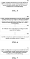
- FIG. 4 is a schematic diagram of a method for configuring information in the embodiments of a first aspect. As shown in FIG. 4 , the method includes: operation 401, receiving an RRC reconfiguration message, wherein the RRC reconfiguration message indicates relevant information on a topology to which a default uplink BAP routing ID configured for an IAB-node belongs.
- this IAB-node may be a boundary IAB-node, such as IAB-node 3 as shown in FIG. 2 or FIG. 3 .
- the IAB-node in the present disclosure is not limited to this, and the IAB-node may further be of other types.
- the relevant information on a topology may refer to topology information, and/or cell group (CG) information.
- the topology includes an F1-terminating topology or a non-F1-terminating topology.
- the cell group (CG) information includes master cell group/secondary cell group (MCG/SCG) information.
- the RRC reconfiguration message may have a first indication information for indicating a topology to which a default uplink BAP routing ID belongs.
- the first indication information is used to indicate that the topology to which the default uplink BAP routing ID belongs is an F1-terminating topology or a non-F1-terminating topology. This first indication information may only be required for the boundary IAB-node.
- the topology to which the default uplink BAP routing ID belongs may be indicated by a donor centralized unit (donor-CU) that configures a default uplink BAP routing ID (defaultUL-BAP-RoutingID) field or configures a backhaul adaptation protocol configuration (bap-Config) containing the default uplink BAP routing ID field.
- donor-CU donor centralized unit
- defaultUL-BAP-RoutingID default uplink BAP routing ID
- bap-Config backhaul adaptation protocol configuration
- the default uplink BAP routing ID field or the bap-Config containing the default uplink BAP routing ID field is configured by an F1-terminating donor, the default uplink BAP routing ID belongs to an F1-terminating topology; if the default uplink BAP routing ID field or the bap-Config containing the default uplink BAP routing ID field is configured by a non-F1-terminating donor, the default uplink BAP routing ID belongs to a non-F1-terminating topology.
- the RRC specification may be enhanced in TS 38.331.
- the defaultUL-BAP-RoutingID field in bap-Config IE of the RRC reconfiguration messge may be modified into the form as shown in Table 3 below.
- Table 3 defaultUL-BAP-RoutingID This field is used for IAB-node to configure the default uplink Routing ID in the topology managed by the IAB-donor-CU configuring this field , which is used by IAB-node during IAB-node bootstrapping, migration, IAB-MT RRC resume and IAB-MT RRC re-establishment for F1-C and non-F1 traffic.
- the defaultUL-BAP-RoutingID can be (re-)configured when IAB-node IP address for F1-C related traffic changes. This field is mandatory only for IAB-node bootstrapping.
- whether the default uplink BAP routing ID field or the bap-Config containing the default uplink BAP routing ID field is configured by an F1-terminating donor or by a non-F1-terminating donor may be determined by whether the MN, or the SN is the F1-terminating donor.
- the MN is an F1-terminating donor
- the IAB-node selects MN or SN as an F1-terminating donor.
- the default uplink BAP routing ID field or the bap-Config is included in an RRC reconfiguration message transmitted via SRB3, or the default uplink BAP routing ID field or the bap-Config is included in a multi radio access technology dual connected secondary cell group information element (mrdc-SecondaryCellGroup IE), the default uplink BAP routing ID field or the bap-Config is configured by a secondary node (SN). If the default uplink BAP routing ID field or the bap-Config is included in an RRC reconfiguration message transmitted via SRB1, and is not included in mrdc-SecondaryCellGroup IE, the default uplink BAP routing ID field or the bap-Config is configured by a master node (MN).
- MN master node
- an RRC reconfiguration message will configure a default uplink BH RLC channel (defaultUL-BH-RLC-Channel) for F1-C and non-F1 traffic of an IAB-node.
- the default uplink BH RLC channel may be configured or reconfigured when an IP address corresponding to F1-C related traffic of the IAB-node changes and when a new IP address is anchored in different IAB-donor-DUs.
- a link of the BH RLC channel that is, an uplink parent node link, also equivalent to a cell group, needs to be further indicated.
- the default uplink BH RLC channel refers to an RLC channel on a secondary cell group (SCG), otherwise, it refers to a radio link control (RLC) channel on a master cell group (MCG).
- a parent node of the IAB-node may belong to different IAB-donor-CUs, that is, a boundary IAB-node may have two IAB-donor-CUs. Both MN (master node) and SN (secondary node) may serve as an F1-terminating donor node. If the IAB-node establishes an NR-DC before F1-C connection is established, the IAB-node may implicitly conclude that MN or SN is an F1-terminating donor, for example, based on an entity that provides a default BAP configuration.
- the default uplink BH RLC channel may further refer to the SCG. That is, if the IAB-MT operates other than in an EN-DC scenario, the default uplink BH RLC channel may refer to an RLC channel on the MCG or the SCG.
- an F1AP When routing is performed at a BAP sublayer, if an F1AP does not configure or reconfigure a backhaul routing configuration after RRC configures or reconfigures defaultUL-BH-RLC-Channel at a latest time, an egress link needs to be selected according to the configured defaultUL-BH-RLC-Channel. Therefore, ambiguity of the default uplink BH RLC channel leads to ambiguity of the selection of the egress link, and topology information or cell group information needs to be further specified.
- embodiments of a second aspect of the present disclosure provide a method for configuring information.
- the method is applied to an IAB-node.
- FIG. 5 is a schematic diagram of a method for configuring information in the embodiments of a second aspect. As shown in FIG. 5 , the method includes: operation 501, receiving an RRC reconfiguration message, wherein the RRC reconfiguration message indicates information on a topology to which a default uplink BH RLC channel configured for an IAB-node belongs.
- the IAB-node does not operate in EN-DC.
- This IAB-node may be a boundary IAB-node, such as IAB-node 3 as shown in FIG. 2 or FIG. 3 .
- the IAB-node in the present disclosure is not limited to this, and the IAB-node may further be of other types.
- the information on a topology may refer to topology information, and/or cell group information.
- the topology includes an F1-terminating topology or a non-F1-terminating topology.
- the cell group information includes master cell group/secondary cell group (MCG/SCG) information.
- the RRC reconfiguration message may have a second indication information for indicating that a topology to which a default uplink BH RLC channel belongs is an F1-terminating topology or a non-F1-terminating topology, or, the second indication information is used to indicate that the default uplink BH RLC channel refers to an RLC channel on a master cell group (MCG) or an RLC channel on a secondary cell group (SCG).
- MCG master cell group
- SCG secondary cell group
- This second indication information may be mandatory for a dual-connected node, or an NR-DC node, or a boundary IAB-node.
- the default uplink BH RLC channel (defaultUL-BH-RLC-Channel) field may refer to an RLC channel on an MCG or an RLC channel on an SCG
- a cell group to which the default uplink BH RLC channel refers may be indicated by a donor centralized unit (donor-CU) that configures a default uplink BH RLC channel (defaultUL-BH-RLC-Channel) field or configures bap-Config containing the default uplink BH RLC channel field.
- donor-CU donor centralized unit
- bap-Config containing the default uplink BH RLC channel field.
- the default uplink BH RLC channel refers to the RLC channel on the MCG
- the default uplink BH RLC channel refers to the RLC channel on the SCG. That is to say, for an IAB-node (such as a boundary IAB-node), the default uplink BH RLC channel refers to an RLC channel on a backhaul link configured by a donor-CU that configures this field.
- the RRC specification may be enhanced in TS 38.331. Enhancement shown in Table 4 may be performed in defaultUL-BH-RLC-Channel field in bap-Config IE of the RRC reconfiguration message. Table 4 defaultUL-BH-RLC-Channel This field is used for IAB-nodes to configure the default uplink BH RLC channel, which is used by IAB-node during IAB-node bootstrapping, migration, IAB-MT RRC resume and IAB-MT RRC re-establishment for F1-C and non-F1 traffic.
- the defaultUL-BH-RLC-Channel can be (re-)configured when IAB-node IP address for F1-C related traffic changes, and the new IP address is anchored at a different IAB-donor-DU. This field is mandatory for IAB-node bootstrapping. If the IAB-MT is operating in EN-DC, the default uplink BH RLC channel is referring to an RLC channel on the SCG; Otherwise, it is referring to an RLC channel on either the MCG or the SCG depending on whether MN or SN configures this field
- the default uplink BH RLC channel field or bap-Config is included in an RRC reconfiguration message transmitted via SRB1 and is not included in a multi radio access technology dual connected secondary cell group information element (mrdc-SecondaryCellGroup IE), the default uplink BH RLC channel field or bap-Config is configured by a master node (MN); if the default uplink BH RLC channel field or bap-Config is included in an RRC reconfiguration message transmitted via SRB3, or the default uplink BH RLC channel field or bap-Config is included in mrdc-SecondaryCellGroup IE, the default uplink BH RLC channel field or bap-Config is configured by a secondary node (SN).
- MN master node
- SN secondary node
- an F1AP When routing is performed at a BAP sublayer, if an F1AP does not configure or reconfigure a backhaul routing configuration after RRC configures or reconfigures a default uplink BH RLC channel at a latest time, an egress link is selected according to a cell group to which the default uplink BH RLC channel corresponds.
- the IAB-node selects an egress link according to a cell group to which the default uplink BH RLC channel corresponds.
- F1AP F1 application protocol
- a descendant node of a boundary node may use the same inter-donor (or inter-Cu) topology adaptation procedure. For example, after an IAB-MT of the boundary node is migrated to donor-CU2, or establishes RRC with donor-CU2, an IAB-DU of the boundary node still maintains F1 connection with donor-CU1, and the descendant node (such as IAB-node 4) still maintains RRC connection and F1 connection with donor-CU1.
- donor-CU2 Since the descendant node of the boundary node needs to migrate a transport path of the F1 connection to a non-F1-terminating topology, donor-CU2 needs to provide the descendant node with new TNL (transport network layer) addresses i.e., IP addresses according to a request of donor-CU1.
- TNL transport network layer
- One or more of these new TNL addresses are anchored to donor-DUs in a topology of donor-CU2, such as donor-DU2.
- Donor-CU2 transmits these new TNL addresses to donor-CU1 via an XnAP message, such as an IAB Transport Migration Management Response message.
- Donor-CU2 further provides layer 2 information under its topology to donor-CU1, such as an uplink BAP routing identity, containing a BAP address of a donor-DU such as donor-DU2 in the topology.
- Donor-CU1 configures an IP address for the descendant node via an RRCReconfiguration message.
- Configuration of the IP Address uses IAB-IP-AddressConfiguration IE in RRC reconfiguration, which contains the IP Address, a usage of the IP address, and a field such as a BAP address of the donor-DU (iab-donor-DU-BAP-Address) corresponding to the IP address.
- a BAP address contained in a routing ID is obtained through a BAP routing ID configured for the data traffic.
- This address is a BAP address of a destination donor-DU.
- IAB-IP-AddressConfiguration configuration an IP address corresponding to the BAP address of the donor-DU is searched, and this IP address is selected as an IP address used by the traffic to perform uplink transmission.
- embodiments of the third aspect provide a method for configuring information, the method is applicable to an IAB-node.
- FIG. 6 is a schematic diagram of a method for configuring information in the embodiments of a third aspect. As shown in FIG. 6 , the method includes: operation 601, receiving an RRC reconfiguration message, wherein the RRC reconfiguration message configures a first donor-DU BAP address for an IAB-node, the first donor-DU BAP address referring to a donor distributed unit (donor-DU2) under a second topology.
- the RRC reconfiguration message configures a first donor-DU BAP address for an IAB-node, the first donor-DU BAP address referring to a donor distributed unit (donor-DU2) under a second topology.
- this IAB-node may be a descendant node of a boundary IAB-node, such as IAB-node 4 as shown in FIG. 2 or FIG. 3 .
- the IAB-node in the present disclosure is not limited to this, and the IAB-node may further be of other types.
- the second topology refers to a topology different from a topology to which the IAB-node belongs.
- the IAB-node belongs to an F1-terminating topology of the boundary node, that is, a first topology
- the second topology is a non-F1-terminating topology of the boundary node.
- IP address configuration of the RRC reconfiguration message may include the first donor-DU BAP address.
- the IAB-node is configured with an uplink BAP routing ID which contains the first donor-DU BAP address.
- the method further includes:
- CU1 may assign a first donor-DU BAP address to donor-DU2 in the topology of CU1, the first donor-DU BAP address may be called a pseudo BAP address or an alias address.
- CU1 may configure an uplink BAP routing ID for a descendant node, including the first donor-DU BAP address indicating donor-DU2.
- a BAP address for donor-DU2 in IAB-IP-AddressConfiguration is also the first donor-DU BAP address of donor-DU2, not an actual BAP address of donor-DU2 in the topology of CU2.
- the BAP address of IAB-donor-DU in an IP address configuration may be the first donor-DU BAP address
- the first donor-DU BAP address refers to an IAB-donor-DU (such as donor-DU2 in FIG. 2 and 3 ) underneath a non-F1-terminating donor CU of the boundary IAB-node.
- Enhancement shown in Table 5 may be performed in iab-donor-DU-BAP-Address field in IAB-IP-AddressConfiguration IE of the RRC reconfiguration message.
- Table 5 iab-donor-DU-BAP-Address This field is used to indicate the BAP address of the IAB-donor-DU where the IP address is anchored. For a boundary IAB node's descendant node, this field may be a pseudo BAP address referring to an IAB-donor-DU underneath the boundary IAB node's non-F1-terminating donor-CU
- the IAB-node in a case of receiving an IAB IP address addition/modification list (iab-IP-AddressToAddModList) contained in an RRC reconfiguration message, the IAB-node saves an IP address in the list and the first donor-DU BAP address to which the IP address corresponds.
- the IP address may be IPv4, or may be IPv6 address.
- the IP address may be used for F1-C, F1-U, non-F1 traffic, etc.
- a situation in which a BAP address of a donor-DU is a pseudo address may be coped with.
- Embodiments of a fourth aspect of the present disclosure provide a method for configuring information, corresponding to the method for configuring information in the embodiments of the first aspect.
- the method is applied to a donor centralized unit (CU), such as donor-CU1 or donor-CU2 in FIG. 2 or FIG. 3 .
- CU donor centralized unit
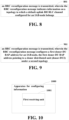
- FIG. 7 is a schematic diagram of a method for configuring information in the embodiments of a fourth aspect, as shown in FIG. 7 , the method includes: operation 701, transmitting an RRC reconfiguration message, wherein the RRC reconfiguration message indicates information on a topology to which a default uplink BAP routing ID configured for an IAB-node belongs.
- this IAB-node may be a boundary IAB-node, such as IAB-node 3 as shown in FIG. 2 or FIG. 3 .
- the IAB-node in the present disclosure is not limited to this, and the IAB-node may further be of other types.
- the information on a topology may refer to topology information, and/or cell group information.
- the topology includes an F1-terminating topology or a non-F1-terminating topology.
- the cell group (CG) information includes master cell group/secondary cell group (MCG/SCG) information.
- the RRC reconfiguration message may have a first indication information for indicating a topology to which a default uplink BAP routing ID belongs.
- the first indication information is used to indicate that the topology to which the default uplink BAP routing ID belongs is an F1-terminating topology or a non-F1-terminating topology. This first indication information may only be required for the boundary IAB-node.
- the topology to which the default uplink BAP routing ID belongs may be indicated by a donor centralized unit (donor-CU) that configures a default uplink BAP routing ID (defaultUL-BAP-RoutingID) field or configures a backhaul adaptation protocol configuration (bap-Config) containing the default uplink BAP routing ID field.
- donor-CU donor centralized unit
- defaultUL-BAP-RoutingID default uplink BAP routing ID
- bap-Config backhaul adaptation protocol configuration
- the default uplink BAP routing ID field or the bap-Config containing the default uplink BAP routing ID field is configured by an F1-terminating donor, the default uplink BAP routing ID belongs to an F1-terminating topology; if the default uplink BAP routing ID field or the bap-Config containing the default uplink BAP routing ID field is configured by a non-F1-terminating donor, the default uplink BAP routing ID belongs to a non-F1-terminating topology.
- Embodiments of a fifth aspect of the present disclosure provide a method for configuring information, corresponding to the method for configuring information in the embodiments of the second aspect.
- the method is applied to a donor centralized unit (CU), such as donor-CU1 or donor-CU2 as shown in FIG. 2 or FIG. 3 .
- CU donor centralized unit
- FIG. 8 is a schematic diagram of a method for configuring information in the embodiments of a fifth aspect. As shown in FIG. 8 , the method includes: operation 801, transmitting an RRC reconfiguration message, wherein the RRC reconfiguration message indicates information on a topology to which a default uplink BH RLC channel configured for an IAB-node belongs.
- the IAB-node does not operate in EN-DC.
- This IAB-node may be a boundary IAB-node, such as IAB-node 3 as shown in FIG. 2 or FIG. 3 .
- the IAB-node in the present disclosure is not limited to this, and the IAB-node may further be of other types.
- the information on a topology may refer to topology information, and/or cell group information.
- the topology includes an F1-terminating topology or a non-F1-terminating topology.
- the cell group information includes master cell group/secondary cell group (MCG/SCG) information.
- the RRC reconfiguration message may have a second indication information for indicating that a topology to which a default uplink BH RLC channel belongs is an F1-terminating topology or a non-F1-terminating topology, or, the second indication information is used to indicate that the default uplink BH RLC channel refers to an RLC channel on a master cell group (MCG) or an RLC channel on a secondary cell group (SCG).
- MCG master cell group
- SCG secondary cell group
- This second indication information may be for a dual-connected node, or an NR-DC node, or a boundary IAB-node is required.
- the default uplink BH RLC channel (defaultUL-BH-RLC-Channel) field may refer to an RLC channel on an MCG or an RLC channel on an SCG
- a cell group to which the default uplink BH RLC channel refers may be indicated by a donor centralized unit (donor-CU) that configures a default uplink BH RLC channel (defaultUL-BH-RLC-Channel) field or configures bap-Config containing the default uplink BH RLC channel field.
- donor-CU donor centralized unit
- bap-Config containing the default uplink BH RLC channel field
- the default uplink BH RLC channel refers to the RLC channel on the MCG
- the default uplink BH RLC channel refers to the RLC channel on the SCG. That is to say, for an IAB-node (such as a boundary IAB-node), the default uplink BH RLC channel refers to an RLC channel on a backhaul link configured by a donor-CU that configures this field.
- the IAB-node selects an egress link according to a cell group to which the default uplink BH RLC channel corresponds.
- F1AP F1 application protocol
- Embodiments of a sixth aspect provide a method for configuring information, corresponding to the method for configuring information in the embodiments of the third aspect.
- the method is applied to a donor centralized unit (CU), such as donor-CU1 as shown in FIG. 2 or FIG. 3 .
- CU donor centralized unit
- FIG. 9 is a schematic diagram of a method for configuring information in the embodiments of a sixth aspect. As shown in FIG. 9 , the method includes: operation 901, transmitting an RRC reconfiguration message, wherein the RRC reconfiguration message configures a first donor-DU BAP address for an IAB-node, the first donor-DU BAP address referring to a donor distributed unit (donor-DU2) under a second topology.
- operation 901 transmitting an RRC reconfiguration message, wherein the RRC reconfiguration message configures a first donor-DU BAP address for an IAB-node, the first donor-DU BAP address referring to a donor distributed unit (donor-DU2) under a second topology.
- this IAB-node may be a descendant node of a boundary IAB-node, such as IAB-node 4 as shown in FIG. 2 or FIG. 3 .
- the IAB-node in the present disclosure is not limited to this, and the IAB-node may further be of other types.
- the second topology refers to a topology different from a topology to which the IAB-node belongs.
- the IAB-node belongs to an F1-terminating topology of the boundary node
- the second topology is a non-F1-terminating topology of the boundary node.
- IP address configuration of the RRC reconfiguration message may include the first donor-DU BAP address.
- a CU may configure the IAB-node with an uplink BAP routing ID which contains the first donor-DU BAP address.
- donor-CU1 may assign a first donor-DU BAP address to donor-DU2 in the topology of CU1, the first donor-DU BAP address may be called a pseudo BAP address or an alias address.
- CU1 may configure an uplink BAP routing ID for a descendant node, including the first donor-DU BAP address indicating donor-DU2.
- a BAP address for donor-DU2 in IAB-IP-AddressConfiguration is also the first donor-DU BAP address of donor-DU2, not an actual BAP address of donor-DU2 in the topology of CU2.
- the BAP address of IAB-donor-DU in an IP address configuration may be the first donor-DU BAP address
- the first donor-DU BAP address refers to an IAB-donor-DU (such as donor-DU2 in FIG. 2 and 3 ) under a non-F1-terminating donor CU of the boundary IAB-node.
- an RRC reconfiguration message transmitted by a CU may contain an IAB IP address addition/modification list (iab-IP-AddressToAddModList), and the list includes an IP address and the first donor-DU BAP address to which the IP address corresponds.
- the IP address may be IPv4, or may be IPv6 address.
- the IP address may be used for F1-C, F1-U, non-F1 traffic, etc.
- a situation in which a BAP address of a donor-DU is a pseudo address may be coped with.
- Embodiments of a seventh aspect of the present disclosure provide an apparatus for configuring information, corresponding to the method for configuring information in the embodiments of the first aspect.
- the apparatus is applied to an IAB-node.
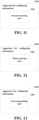
- FIG. 10 is a schematic diagram of an apparatus for configuring information in the embodiments of a seventh aspect.
- the apparatus 1000 for configuring information includes: a first receiving unit 1001 configured to receive an RRC reconfiguration message, wherein the RRC reconfiguration message indicates information on a topology to which a default uplink BAP routing ID configured for an IAB-node belongs.
- this IAB-node may be a boundary IAB-node, such as IAB-node 3 as shown in FIG. 2 or FIG. 3 .
- the IAB-node in the present disclosure is not limited to this, and the IAB-node may further be of other types.
- the information on a topology may refer to topology information, and/or cell group information.
- the topology includes an F1-terminating topology or a non-F1-terminating topology.
- the cell group (CG) information includes master cell group/secondary cell group (MCG/SCG) information.
- the RRC reconfiguration message may have a first indication information for indicating a topology to which a default uplink BAP routing ID belongs.
- the first indication information is used to indicate that the topology to which the default uplink BAP routing ID belongs is an F1-terminating topology or a non-F1-terminating topology. This first indication information may only be required for the boundary IAB-node.
- the topology to which the default uplink BAP routing ID belongs may be indicated by a donor centralized unit (donor-CU) that configures a default uplink BAP routing ID (defaultUL-BAP-RoutingID) field or configures a backhaul adaptation protocol configuration (bap-Config) containing the default uplink BAP routing ID field.
- donor-CU donor centralized unit
- defaultUL-BAP-RoutingID default uplink BAP routing ID
- bap-Config backhaul adaptation protocol configuration
- the default uplink BAP routing ID field or the bap-Config containing the default uplink BAP routing ID field is configured by an F1-terminating donor, the default uplink BAP routing ID belongs to an F1-terminating topology; if the default uplink BAP routing ID field or the bap-Config containing the default uplink BAP routing ID field is configured by a non-F1-terminating donor, the default uplink BAP routing ID belongs to a non-F1-terminating topology.
- the default uplink BAP routing ID field or the bap-Config containing the default uplink BAP routing ID field configured by an F1-terminating donor or by a non-F1-terminating donor may be determined by a MN, or by a SN or by the F1-terminating donor.
- the MN is an F1-terminating donor
- the IAB-node selects MN or SN as an F1-terminating donor.
- the default uplink BAP routing ID field or the bap-Config is included in an RRC reconfiguration message transmitted via SRB3, or the default uplink BAP routing ID field or the bap-Config is included in a multi radio access technology dual connected secondary cell group information element (mrdc-SecondaryCellGroup IE), the default uplink BAP routing ID field or the bap-Config is configured by a secondary node (SN). If the default uplink BAP routing ID field or the bap-Config is included in an RRC reconfiguration message transmitted via SRB1, and is not included in mrdc-SecondaryCellGroup IE, the default uplink BAP routing ID field or the bap-Config is configured by a master node (MN).
- MN master node
- Embodiments of an eighth aspect of the present disclosure provide an apparatus for configuring information, corresponding to the method for configuring information in the embodiments of the second aspect.
- the apparatus is applied to an IAB-node.
- FIG. 11 is a schematic diagram of an apparatus for configuring information in the embodiments of an eighth aspect.
- the apparatus 1100 for configuring information includes: a second receiving unit 1101 configured to receive an RRC reconfiguration message, wherein the RRC reconfiguration message indicates information on a topology to which a default uplink BH RLC channel configured for an IAB-node belongs.
- the IAB-node does not operate in EN-DC.
- This IAB-node may be a boundary IAB-node, such as IAB-node 3 as shown in FIG. 2 or FIG. 3 .
- the IAB-node in the present disclosure is not limited to this, and the IAB-node may further be of other types.
- the information on a topology may refer to topology information, and/or cell group information.
- the topology includes an F1-terminating topology or a non-F1-terminating topology.
- the cell group information includes master cell group/secondary cell group (MCG/SCG) information.
- the RRC reconfiguration message may have a second indication information for indicating that a topology to which a default uplink BH RLC channel belongs is an F1-terminating topology or a non-F1-terminating topology, or, the second indication information is used to indicate that the default uplink BH RLC channel refers to an RLC channel on a master cell group (MCG) or an RLC channel on a secondary cell group (SCG).
- MCG master cell group
- SCG secondary cell group
- This second indication information may be for a dual-connected node, or an NR-DC node, or a boundary IAB-node is required.
- the default uplink BH RLC channel (defaultUL-BH-RLC-Channel) field may refer to an RLC channel on an MCG or an RLC channel on an SCG
- a cell group to which the default uplink BH RLC channel refers may be indicated by a donor centralized unit (donor-CU) that configures a default uplink BH RLC channel (defaultUL-BH-RLC-Channel) field or configures bap-Config containing the default uplink BH RLC channel field.
- donor-CU donor centralized unit
- bap-Config containing the default uplink BH RLC channel field
- the default uplink BH RLC channel refers to the RLC channel on the MCG
- the default uplink BH RLC channel refers to the RLC channel on the SCG. That is to say, for an IAB-node (such as a boundary IAB-node), the default uplink BH RLC channel refers to an RLC channel on a backhaul link configured by a donor-CU that configures this field.
- the default uplink BH RLC channel field or bap-Config is included in an RRC reconfiguration message transmitted via SRB1 and is not included in a multi radio access technology dual connected secondary cell group information element (mrdc-SecondaryCellGroup IE), the default uplink BH RLC channel field or bap-Config is configured by a master node (MN); if the default uplink BH RLC channel field or bap-Config is included in an RRC reconfiguration message transmitted via SRB3, or the default uplink BH RLC channel field or bap-Config is included in mrdc-SecondaryCellGroup IE, the default uplink BH RLC channel field or bap-Config is configured by a secondary node (SN).
- MN master node
- SN secondary node
- an F1AP When routing is performed at a BAP sublayer, if an F1AP does not configure or reconfigure a backhaul routing configuration after RRC configures or reconfigures a default uplink BH RLC channel at a latest time, an egress link is selected according to a cell group to which the default uplink BH RLC channel corresponds.
- the IAB-node selects an egress link according to a cell group to which the default uplink BH RLC channel corresponds.
- F1AP F1 application protocol
- Embodiments of a ninth aspect provide an apparatus for configuring information, corresponding to the method for configuring information in the embodiments of the third aspect.
- the apparatus is applied to an IAB-node.
- FIG. 12 is a schematic diagram of an apparatus for configuring information in the embodiments of a ninth aspect.
- the apparatus for configuring information includes: a third receiving unit 1201 configured to receive an RRC reconfiguration message, wherein the RRC reconfiguration message configures a first donor-DU BAP address for an IAB-node, the first donor-DU BAP address refering to a donor distributed unit (donor-DU2) under a second topology.
- a third receiving unit 1201 configured to receive an RRC reconfiguration message, wherein the RRC reconfiguration message configures a first donor-DU BAP address for an IAB-node, the first donor-DU BAP address refering to a donor distributed unit (donor-DU2) under a second topology.
- donor-DU2 donor distributed unit
- this IAB-node may be a descendant node of a boundary IAB-node, such as IAB-node 4 as shown in FIG. 2 or FIG. 3 .
- the IAB-node in the present disclosure is not limited to this, and the IAB-node may further be of other types.
- the second topology refers to a topology different from a topology to which the IAB-node belongs.
- the IAB-node belongs to an F1-terminating topology of the boundary node
- the second topology is a non-F1-terminating topology of the boundary node.
- IP address configuration of the RRC reconfiguration message may include the first donor-DU BAP address.
- the IAB-node is configured with an uplink BAP routing ID which contains the first donor-DU BAP address.
- the third receiving unit 1201 further performs the following operations:
- CU1 may assign a first donor-DU BAP address to donor-DU2 in the topology of CU1, the first donor-DU BAP address may be called a pseudo BAP address or an alias address.
- CU1 may configure an uplink BAP routing ID for a descendant node, including the first donor-DU BAP address indicating donor-DU2.
- a BAP address for donor-DU2 in IAB-IP-AddressConfiguration is also the first donor-DU BAP address of donor-DU2, not an actual BAP address of donor-DU2 in the topology of CU2.
- the BAP address of IAB-donor-DU in an IP address configuration may be the first donor-DU BAP address
- the first donor-DU BAP address refers to an IAB-donor-DU (such as donor-DU2 in FIG. 2 and 3 ) under a non-F1-terminating donor CU of the boundary IAB-node.
- the IAB-node in a case of receiving an IAB IP address addition/modification list (iab-IP-AddressToAddModList) contained in an RRC reconfiguration message, the IAB-node saves an IP address in the list and the first donor-DU BAP address to which the IP address corresponds.
- the IP address may be IPv4, or may be IPv6 address.
- the IP address may be used for F1-C, F1-U, non-F1 traffic, etc.
- a situation in which a BAP address of a donor-DU is a pseudo address may be coped with.
- Embodiments of a tenth aspect of the present disclosure provide a method for configuring information, corresponding to the method for configuring information in the embodiments of the fourth aspect.
- the method is applied to a donor centralized unit (CU), such as donor-CU1 or donor-CU2 in FIG. 2 or FIG. 3 .
- CU donor centralized unit
- FIG. 13 is a schematic diagram of an apparatus for configuring information in the embodiments of a tenth aspect.
- the apparatus 1300 includes: a first transmitting unit 1301 configured to transmit an RRC reconfiguration message, wherein the RRC reconfiguration message indicates information on a topology to which a default uplink BAP routing ID configured for an IAB-node belongs.
- this IAB-node may be a boundary IAB-node, such as IAB-node 3 as shown in FIG. 2 or FIG. 3 .
- the IAB-node in the present disclosure is not limited to this, and the IAB-node may further be of other types.
- the information on a topology may refer to topology information, and/or cell group information.
- the topology includes an F1-terminating topology or a non-F1-terminating topology.
- the cell group (CG) information includes master cell group/secondary cell group (MCG/SCG) information.
- the RRC reconfiguration message may have a first indication information for indicating a topology to which a default uplink BAP routing ID belongs.
- the first indication information is used to indicate that the topology to which the default uplink BAP routing ID belongs is an F1-terminating topology or a non-F1-terminating topology. This first indication information may only be required for the boundary IAB-node.
- the topology to which the default uplink BAP routing ID belongs may be indicated by a donor centralized unit (donor-CU) that configures a default uplink BAP routing ID (defaultUL-BAP-RoutingID) field or configures a backhaul adaptation protocol configuration (bap-Config) containing the default uplink BAP routing ID field.
- donor-CU donor centralized unit
- defaultUL-BAP-RoutingID default uplink BAP routing ID
- bap-Config backhaul adaptation protocol configuration
- the default uplink BAP routing ID field or the bap-Config containing the default uplink BAP routing ID field is configured by an F1-terminating donor, the default uplink BAP routing ID belongs to an F1-terminating topology; if the default uplink BAP routing ID field or the bap-Config containing the default uplink BAP routing ID field is configured by a non-F1-terminating donor, the default uplink BAP routing ID belongs to a non-F1-terminating topology.
- Embodiments of an eleventh aspect of the present disclosure provide an apparatus for configuring information, corresponding to the method for configuring information in the embodiments of the fifth aspect.
- the method is applied to a donor centralized unit (CU), such as donor-CU1 or donor-CU2 as shown in FIG. 2 or FIG. 3 .
- CU donor centralized unit
- FIG. 14 is a schematic diagram of an apparatus for configuring information in the embodiments of an eleventh aspect.
- the apparatus 1400 includes: a second transmitting unit 1401 configured to transmit an RRC reconfiguration message, wherein the RRC reconfiguration message indicates information on a topology to which a default uplink BH RLC channel configured for an IAB-node belongs.
- the IAB-node does not operate in EN-DC.
- This IAB-node may be a boundary IAB-node, such as IAB-node 3 as shown in FIG. 2 or FIG. 3 .
- the IAB-node in the present disclosure is not limited to this, and the IAB-node may further be of other types.
- the information on a topology may refer to topology information, and/or cell group information.
- the topology includes an F1-terminating topology or a non-F1-terminating topology.
- the cell group information includes master cell group/secondary cell group (MCG/SCG) information.
- the RRC reconfiguration message may have a second indication information for indicating that a topology to which a default uplink BH RLC channel belongs is an F1-terminating topology or a non-F1-terminating topology, or, the second indication information is used to indicate that the default uplink BH RLC channel refers to an RLC channel on a master cell group (MCG) or an RLC channel on a secondary cell group (SCG).
- MCG master cell group
- SCG secondary cell group
- This second indication information may be for a dual-connected node, or an NR-DC node, or a boundary IAB-node is required.
- the default uplink BH RLC channel (defaultUL-BH-RLC-Channel) field may refer to an RLC channel on an MCG or an RLC channel on an SCG
- a cell group to which the default uplink BH RLC channel refers may be indicated by a donor centralized unit (donor-CU) that configures a default uplink BH RLC channel (defaultUL-BH-RLC-Channel) field or configures bap-Config containing the default uplink BH RLC channel field.
- donor-CU donor centralized unit
- bap-Config containing the default uplink BH RLC channel field
- the default uplink BH RLC channel refers to the RLC channel on the MCG
- the default uplink BH RLC channel refers to the RLC channel on the SCG. That is to say, for an IAB-node (such as a boundary IAB-node), the default uplink BH RLC channel refers to an RLC channel on a backhaul link configured by a donor-CU that configures this field.
- the IAB-node selects an egress link according to a cell group to which the default uplink BH RLC channel corresponds.
- F1AP F1 application protocol
- Embodiments of a twelfth aspect provide an apparatus for configuring information, corresponding to the method for configuring information in the embodiments of the sixth aspect.
- the apparatus is applied to a donor centralized unit (CU), such as donor-CU1 as shown in FIG. 2 or FIG. 3 .
- CU donor centralized unit
- FIG. 15 is a schematic diagram of a method for configuring information in the embodiments of a twelfth aspect.
- the apparatus 1500 includes: a third transmitting unit 1501 configured to transmit an RRC reconfiguration message, wherein the RRC reconfiguration message configures a first donor-DU BAP address for an IAB-node, the first donor-DU BAP address referring to a donor distributed unit (donor-DU2) under a second topology.
- a third transmitting unit 1501 configured to transmit an RRC reconfiguration message, wherein the RRC reconfiguration message configures a first donor-DU BAP address for an IAB-node, the first donor-DU BAP address referring to a donor distributed unit (donor-DU2) under a second topology.
- donor-DU2 donor distributed unit
- this IAB-node may be a descendant node of a boundary IAB-node, such as IAB-node 4 as shown in FIG. 2 or FIG. 3 .
- the IAB-node in the present disclosure is not limited to this, and the IAB-node may further be of other types.
- the second topology refers to a topology different from a topology to which the IAB-node belongs.
- the IAB-node belongs to an F1-terminating topology of the boundary node
- the second topology is a non-F1-terminating topology of the boundary node.
- IP address configuration of the RRC reconfiguration message may include the first donor-DU BAP address.
- a CU may configure the IAB-node with an uplink BAP routing ID which contains the first donor-DU BAP address.
- donor-CU1 may assign a first donor-DU BAP address to donor-DU2 in the topology of CU1, the first donor-DU BAP address may be called a pseudo BAP address or an alias address.
- CU1 may configure an uplink BAP routing ID for a descendant node, including the first donor-DU BAP address indicating donor-DU2.
- a BAP address for donor-DU2 in IAB-IP-AddressConfiguration is also the first donor-DU BAP address of donor-DU2, not an actual BAP address of donor-DU2 in the topology of CU2.
- the BAP address of IAB-donor-DU in an IP address configuration may be the first donor-DU BAP address
- the first donor-DU BAP address refers to an IAB-donor-DU (such as donor-DU2 in FIG. 2 and 3 ) under a non-F1-terminating donor CU of the boundary IAB-node.
- an RRC reconfiguration message transmitted by a CU may contain an IAB IP address addition/modification list (iab-IP-AddressToAddModList), and the list includes an IP address and the first donor-DU BAP address to which the IP address corresponds.
- the IP address may be IPv4, or may be IPv6 address.
- the IP address may be used for F1-C, F1-U, non-F1 traffic, etc.
- a situation in which a BAP address of a donor-DU is a pseudo address may be coped with.
- Embodiments of the present disclosure further provide a communication system, which may include an IAB-node and a base station CU. At least one of a MT of the IAB-node, a DU of the IAB-node, and the base station CU may have the composition of the electronic device shown in FIG. 16 .
- FIG. 16 is a schematic diagram of composition of an electronic device in the embodiments of the present disclosure.
- the electronic device 1600 may include: a processor 1610 (such as a central processing unit (CPU)) and a memory 1620; the memory 1620 is coupled to the processor 1610.
- the memory 1620 may store various data; moreover, further stores a program 1630 for information processing, and executes the program 1630 under the control of the processor 1610.
- the processor 1610 may be configured to execute a program to implement the method in the embodiments of the first to sixth aspects.
- the electronic device 1600 may further include: a transceiver 1640 and an antenna 1650, etc.; wherein the functions of said components are similar to relevant arts, which are not repeated here. It's worth noting that the electronic device 1600 does not have to include all the components shown in FIG. 16 . Moreover, the electronic device 1600 may also include components not shown in FIG. 16 , related arts may be referred to.
- the embodiments of the present disclosure further provide a computer program, wherein when the program is executed in an IAB-node, the program enables the IAB-node to execute the method as described in the embodiments of the first to third aspects.
- the embodiments of the present disclosure further provide a computer program, wherein when the program is executed in a CU node, the program enables the CU node to execute the method as described in the embodiments of the fourth to sixth aspects.
- the embodiments of the present disclosure further provide a storage medium in which a computer program is stored, wherein the computer program enables a electronic device to execute the method described in the embodiments of the first to sixth aspects.
- the apparatus and method in the present disclosure may be realized by hardware, or may be realized by combining hardware with software.
- the present disclosure relates to such a computer readable program, when the program is executed by a logic component, the computer readable program enables the logic component to realize the apparatus described in the above text or a constituent component, or enables the logic component to realize various methods or steps described in the above text.
- the present disclosure further relates to a storage medium storing the program, such as a hard disk, a magnetic disk, an optical disk, a DVD, a flash memory and the like.
- one or more in the functional block diagram or one or more combinations in the functional block diagram as shown in the drawings may correspond to software modules of a computer program flow, and may also correspond to hardware modules. These software modules may respectively correspond to the steps as shown in the drawings. These hardware modules may be realized by solidifying these software modules e.g. using a field-programmable gate array (FPGA).
- FPGA field-programmable gate array
- a software module may be located in a RAM memory, a flash memory, a ROM memory, an EPROM memory, an EEPROM memory, a register, a hard disk, a mobile magnetic disk, a CD-ROM or a storage medium in any other form as known in this field.
- a storage medium may be coupled to a processor, thereby enabling the processor to read information from the storage medium, and to write the information into the storage medium; or the storage medium may be a constituent part of the processor.
- the processor and the storage medium may be located in an ASIC.
- the software module may be stored in a memory of a mobile terminal, and may also be stored in a memory card of the mobile terminal.
- the software module may be stored in the MEGA-SIM card or the flash memory apparatus with a large capacity.
- One or more in the functional block diagram or one or more combinations in the functional block diagram as described in the drawings may be implemented as a general-purpose processor for performing the functions described in the present disclosure, a digital signal processor (DSP), an application-specific integrated circuit (ASIC), a field-programmable gate array (FPGA) or other programmable logic device, discrete gate or transistor logic device, discrete hardware components or any combination thereof.
- DSP digital signal processor
- ASIC application-specific integrated circuit
- FPGA field-programmable gate array
- One or more in the functional block diagram or one or more combinations in the functional block diagram as described in the drawings may further be implemented as a combination of computer equipments, such as a combination of a DSP and a microprocessor, a plurality of microprocessors, one or more microprocessors combined and communicating with the DSP or any other such configuration.
Landscapes
- Engineering & Computer Science (AREA)
- Computer Networks & Wireless Communication (AREA)
- Signal Processing (AREA)
- Mobile Radio Communication Systems (AREA)
Applications Claiming Priority (1)
| Application Number | Priority Date | Filing Date | Title |
|---|---|---|---|
| PCT/CN2022/085090 WO2023184542A1 (zh) | 2022-04-02 | 2022-04-02 | 配置信息的方法、装置和通信系统 |
Publications (2)
| Publication Number | Publication Date |
|---|---|
| EP4507375A1 true EP4507375A1 (de) | 2025-02-12 |
| EP4507375A4 EP4507375A4 (de) | 2025-08-06 |
Family
ID=88198878
Family Applications (1)
| Application Number | Title | Priority Date | Filing Date |
|---|---|---|---|
| EP22934369.4A Pending EP4507375A4 (de) | 2022-04-02 | 2022-04-02 | Verfahren und vorrichtung zur konfiguration von informationen und kommunikationssystem |
Country Status (6)
| Country | Link |
|---|---|
| US (1) | US20250024544A1 (de) |
| EP (1) | EP4507375A4 (de) |
| JP (1) | JP7806927B2 (de) |
| KR (1) | KR20240154073A (de) |
| CN (1) | CN119014045A (de) |
| WO (1) | WO2023184542A1 (de) |
Family Cites Families (5)
| Publication number | Priority date | Publication date | Assignee | Title |
|---|---|---|---|---|
| US20190394084A1 (en) * | 2018-06-20 | 2019-12-26 | Industrial Technology Research Institute | Network link topology adaptation method for intergrated access and backhaul node and intergrated access and backhaul node using the same |
| CN111526543A (zh) * | 2019-02-02 | 2020-08-11 | 索尼公司 | 电子设备、通信方法和存储介质 |
| CN113556794B (zh) * | 2020-04-23 | 2022-10-28 | 华为技术有限公司 | 通信方法、装置及系统 |
| CN113630815A (zh) * | 2020-05-06 | 2021-11-09 | 索尼公司 | 电子设备、无线通信方法和计算机可读存储介质 |
| CN114071617B (zh) * | 2020-08-07 | 2024-07-02 | 大唐移动通信设备有限公司 | Iab节点组切换中的信息传输方法、装置、设备及系统 |
-
2022
- 2022-04-02 WO PCT/CN2022/085090 patent/WO2023184542A1/zh not_active Ceased
- 2022-04-02 EP EP22934369.4A patent/EP4507375A4/de active Pending
- 2022-04-02 CN CN202280094518.9A patent/CN119014045A/zh active Pending
- 2022-04-02 KR KR1020247032654A patent/KR20240154073A/ko active Pending
- 2022-04-02 JP JP2024554671A patent/JP7806927B2/ja active Active
-
2024
- 2024-09-27 US US18/899,354 patent/US20250024544A1/en active Pending
Also Published As
| Publication number | Publication date |
|---|---|
| KR20240154073A (ko) | 2024-10-24 |
| US20250024544A1 (en) | 2025-01-16 |
| CN119014045A (zh) | 2024-11-22 |
| JP2025510617A (ja) | 2025-04-15 |
| EP4507375A4 (de) | 2025-08-06 |
| JP7806927B2 (ja) | 2026-01-27 |
| WO2023184542A1 (zh) | 2023-10-05 |
Similar Documents
| Publication | Publication Date | Title |
|---|---|---|
| JP7516578B2 (ja) | Iabネットワーク通信方法及び関連デバイス | |
| US20240259776A1 (en) | Integrated access and backhaul communication device and method | |
| US20230100121A1 (en) | Relay communication method and related device | |
| US20230262528A1 (en) | Communication method and related device | |
| JP2023545809A (ja) | グループ移行方法、装置及びシステム | |
| US20240349166A1 (en) | Iab-node device, iab-donor device and topology revoking method | |
| CN117063520A (zh) | 信息收发方法,数据发送方法以及装置 | |
| US20250159734A1 (en) | Mobile node configuration method, mobile node, and donor device | |
| US20250175860A1 (en) | Integrated access and backhaul node migration method and apparatus | |
| WO2023150975A1 (zh) | Iab宿主设备以及传输迁移回退方法 | |
| US20250024544A1 (en) | Method for configuring information and apparatus therefor, and communication system | |
| US20250039058A1 (en) | Method for configuring information and apparatus therefor, and communication system | |
| EP4694229A1 (de) | Verfahren und vorrichtung zum senden und empfangen von signalen und kommunikationssystem | |
| US20250330828A1 (en) | Information processing method and apparatus | |
| US20240397380A1 (en) | Iab-donor device and transport migration management method | |
| EP4478781A1 (de) | Iab-donorvorrichtung und übertragungsmigrationsverwaltungsverfahren | |
| US20240357456A1 (en) | Iab-node device, iab-donor device and path migration method | |
| EP4694324A1 (de) | Migrationsverfahren für verteilte einheit und steuerungsvorrichtung sowie kommunikationssystem | |
| WO2024026803A1 (zh) | 移动节点的配置方法和宿主设备 |
Legal Events
| Date | Code | Title | Description |
|---|---|---|---|
| STAA | Information on the status of an ep patent application or granted ep patent |
Free format text: STATUS: THE INTERNATIONAL PUBLICATION HAS BEEN MADE |
|
| PUAI | Public reference made under article 153(3) epc to a published international application that has entered the european phase |
Free format text: ORIGINAL CODE: 0009012 |
|
| STAA | Information on the status of an ep patent application or granted ep patent |
Free format text: STATUS: REQUEST FOR EXAMINATION WAS MADE |
|
| 17P | Request for examination filed |
Effective date: 20240924 |
|
| AK | Designated contracting states |
Kind code of ref document: A1 Designated state(s): AL AT BE BG CH CY CZ DE DK EE ES FI FR GB GR HR HU IE IS IT LI LT LU LV MC MK MT NL NO PL PT RO RS SE SI SK SM TR |
|
| RIC1 | Information provided on ipc code assigned before grant |
Ipc: H04W 40/24 20090101ALI20250409BHEP Ipc: H04W 88/08 20090101ALI20250409BHEP Ipc: H04W 84/04 20090101ALI20250409BHEP Ipc: H04W 76/20 20180101ALI20250409BHEP Ipc: H04W 76/15 20180101ALI20250409BHEP Ipc: H04W 40/22 20090101ALI20250409BHEP Ipc: H04W 28/02 20090101ALI20250409BHEP Ipc: H04W 36/00 20090101AFI20250409BHEP |
|
| DAV | Request for validation of the european patent (deleted) | ||
| DAX | Request for extension of the european patent (deleted) | ||
| A4 | Supplementary search report drawn up and despatched |
Effective date: 20250709 |
|
| RIC1 | Information provided on ipc code assigned before grant |
Ipc: H04W 36/00 20090101AFI20250702BHEP Ipc: H04W 28/02 20090101ALI20250702BHEP Ipc: H04W 40/22 20090101ALI20250702BHEP Ipc: H04W 76/15 20180101ALI20250702BHEP Ipc: H04W 76/20 20180101ALI20250702BHEP Ipc: H04W 84/04 20090101ALI20250702BHEP Ipc: H04W 88/08 20090101ALI20250702BHEP Ipc: H04W 40/24 20090101ALI20250702BHEP |
|
| RAP1 | Party data changed (applicant data changed or rights of an application transferred) |
Owner name: 1FINITY INC. |