EP4507426A1 - Procédé et appareil de transmission de signal de référence de démodulation, terminal et dispositif côté réseau - Google Patents
Procédé et appareil de transmission de signal de référence de démodulation, terminal et dispositif côté réseau Download PDFInfo
- Publication number
- EP4507426A1 EP4507426A1 EP23778522.5A EP23778522A EP4507426A1 EP 4507426 A1 EP4507426 A1 EP 4507426A1 EP 23778522 A EP23778522 A EP 23778522A EP 4507426 A1 EP4507426 A1 EP 4507426A1
- Authority
- EP
- European Patent Office
- Prior art keywords
- subsequence
- length
- reference signal
- demodulation reference
- target
- Prior art date
- Legal status (The legal status is an assumption and is not a legal conclusion. Google has not performed a legal analysis and makes no representation as to the accuracy of the status listed.)
- Pending
Links
Images





Classifications
-
- H—ELECTRICITY
- H04—ELECTRIC COMMUNICATION TECHNIQUE
- H04L—TRANSMISSION OF DIGITAL INFORMATION, e.g. TELEGRAPHIC COMMUNICATION
- H04L25/00—Baseband systems
- H04L25/02—Details ; arrangements for supplying electrical power along data transmission lines
- H04L25/0202—Channel estimation
- H04L25/0224—Channel estimation using sounding signals
-
- H—ELECTRICITY
- H04—ELECTRIC COMMUNICATION TECHNIQUE
- H04L—TRANSMISSION OF DIGITAL INFORMATION, e.g. TELEGRAPHIC COMMUNICATION
- H04L27/00—Modulated-carrier systems
- H04L27/26—Systems using multi-frequency codes
- H04L27/2601—Multicarrier modulation systems
- H04L27/2602—Signal structure
- H04L27/26035—Maintenance of orthogonality, e.g. for signals exchanged between cells or users, or by using covering codes or sequences
-
- H—ELECTRICITY
- H04—ELECTRIC COMMUNICATION TECHNIQUE
- H04L—TRANSMISSION OF DIGITAL INFORMATION, e.g. TELEGRAPHIC COMMUNICATION
- H04L27/00—Modulated-carrier systems
- H04L27/26—Systems using multi-frequency codes
- H04L27/2601—Multicarrier modulation systems
- H04L27/2602—Signal structure
- H04L27/261—Details of reference signals
-
- H—ELECTRICITY
- H04—ELECTRIC COMMUNICATION TECHNIQUE
- H04L—TRANSMISSION OF DIGITAL INFORMATION, e.g. TELEGRAPHIC COMMUNICATION
- H04L27/00—Modulated-carrier systems
- H04L27/26—Systems using multi-frequency codes
- H04L27/2601—Multicarrier modulation systems
- H04L27/2602—Signal structure
- H04L27/261—Details of reference signals
- H04L27/2613—Structure of the reference signals
-
- H—ELECTRICITY
- H04—ELECTRIC COMMUNICATION TECHNIQUE
- H04L—TRANSMISSION OF DIGITAL INFORMATION, e.g. TELEGRAPHIC COMMUNICATION
- H04L27/00—Modulated-carrier systems
- H04L27/26—Systems using multi-frequency codes
- H04L27/2601—Multicarrier modulation systems
- H04L27/2697—Multicarrier modulation systems in combination with other modulation techniques
-
- H—ELECTRICITY
- H04—ELECTRIC COMMUNICATION TECHNIQUE
- H04L—TRANSMISSION OF DIGITAL INFORMATION, e.g. TELEGRAPHIC COMMUNICATION
- H04L5/00—Arrangements affording multiple use of the transmission path
-
- H—ELECTRICITY
- H04—ELECTRIC COMMUNICATION TECHNIQUE
- H04L—TRANSMISSION OF DIGITAL INFORMATION, e.g. TELEGRAPHIC COMMUNICATION
- H04L5/00—Arrangements affording multiple use of the transmission path
- H04L5/0001—Arrangements for dividing the transmission path
- H04L5/0014—Three-dimensional division
- H04L5/0016—Time-frequency-code
- H04L5/0021—Time-frequency-code in which codes are applied as a frequency-domain sequences, e.g. MC-CDMA
-
- H—ELECTRICITY
- H04—ELECTRIC COMMUNICATION TECHNIQUE
- H04L—TRANSMISSION OF DIGITAL INFORMATION, e.g. TELEGRAPHIC COMMUNICATION
- H04L5/00—Arrangements affording multiple use of the transmission path
- H04L5/003—Arrangements for allocating sub-channels of the transmission path
- H04L5/0048—Allocation of pilot signals, i.e. of signals known to the receiver
-
- H—ELECTRICITY
- H04—ELECTRIC COMMUNICATION TECHNIQUE
- H04L—TRANSMISSION OF DIGITAL INFORMATION, e.g. TELEGRAPHIC COMMUNICATION
- H04L5/00—Arrangements affording multiple use of the transmission path
- H04L5/003—Arrangements for allocating sub-channels of the transmission path
- H04L5/0048—Allocation of pilot signals, i.e. of signals known to the receiver
- H04L5/0051—Allocation of pilot signals, i.e. of signals known to the receiver of dedicated pilots, i.e. pilots destined for a single user or terminal
-
- H—ELECTRICITY
- H04—ELECTRIC COMMUNICATION TECHNIQUE
- H04L—TRANSMISSION OF DIGITAL INFORMATION, e.g. TELEGRAPHIC COMMUNICATION
- H04L5/00—Arrangements affording multiple use of the transmission path
- H04L5/003—Arrangements for allocating sub-channels of the transmission path
- H04L5/0053—Allocation of signalling, i.e. of overhead other than pilot signals
-
- H—ELECTRICITY
- H04—ELECTRIC COMMUNICATION TECHNIQUE
- H04W—WIRELESS COMMUNICATION NETWORKS
- H04W72/00—Local resource management
- H04W72/04—Wireless resource allocation
- H04W72/044—Wireless resource allocation based on the type of the allocated resource
- H04W72/0453—Resources in frequency domain, e.g. a carrier in FDMA
-
- H—ELECTRICITY
- H04—ELECTRIC COMMUNICATION TECHNIQUE
- H04W—WIRELESS COMMUNICATION NETWORKS
- H04W72/00—Local resource management
- H04W72/12—Wireless traffic scheduling
- H04W72/1263—Mapping of traffic onto schedule, e.g. scheduled allocation or multiplexing of flows
- H04W72/1273—Mapping of traffic onto schedule, e.g. scheduled allocation or multiplexing of flows of downlink data flows
-
- H—ELECTRICITY
- H04—ELECTRIC COMMUNICATION TECHNIQUE
- H04W—WIRELESS COMMUNICATION NETWORKS
- H04W72/00—Local resource management
- H04W72/20—Control channels or signalling for resource management
- H04W72/21—Control channels or signalling for resource management in the uplink direction of a wireless link, i.e. towards the network
-
- H—ELECTRICITY
- H04—ELECTRIC COMMUNICATION TECHNIQUE
- H04W—WIRELESS COMMUNICATION NETWORKS
- H04W72/00—Local resource management
- H04W72/20—Control channels or signalling for resource management
- H04W72/23—Control channels or signalling for resource management in the downlink direction of a wireless link, i.e. towards a terminal
-
- H—ELECTRICITY
- H04—ELECTRIC COMMUNICATION TECHNIQUE
- H04W—WIRELESS COMMUNICATION NETWORKS
- H04W8/00—Network data management
- H04W8/22—Processing or transfer of terminal data, e.g. status or physical capabilities
- H04W8/24—Transfer of terminal data
Definitions
- the present invention claims priority to Chinese Patent Application No. 202210346947.2, filed with the China National Intellectual Property Administration on April 2, 2022 , and entitled “DEMODULATION REFERENCE SIGNAL TRANSMISSION METHOD AND APPARATUS, TERMINAL, AND NETWORK-SIDE DEVICE", and Chinese Patent Application No. 202211103762.5, filed with the China National Intellectual Property Administration on September 9, 2022 , and entitled “DEMODULATION REFERENCE SIGNAL TRANSMISSION METHOD AND APPARATUS, TERMINAL, AND NETWORK-SIDE DEVICE", both of which are incorporated herein by reference in their entireties.
- This application pertains to the field of mobile communication technologies, and specifically relates to a demodulation reference signal transmission method and apparatus, a terminal, and a network-side device.
- a data channel demodulation reference signal (Demodulation Reference Signal, DMRS) is designed based on a frequency division orthogonal cover code (Frequency Division Orthogonal Cover Code, FD OCC) sequence with a length of 2.
- a type of the DMRS is configuration type 1 (type 1), a maximum quantity of DMRS ports supported by the DMRS is 8; or when a type of the DMRS is configuration type 2 (type 2), a maximum quantity of DMRS ports supported by the DMRS is 12.
- Embodiments of this application provide a demodulation reference signal transmission method and apparatus, a terminal, and a network-side device to resolve a problem that transmitted data flows are limited because an existing DMRS port quantity cannot meet an actual application requirement.
- a demodulation reference signal transmission method is provided. The method is applied to a first communication device and includes:
- a demodulation reference signal transmission apparatus includes:
- a demodulation reference signal transmission method is provided. The method is applied to a second communication device and includes:
- a demodulation reference signal transmission apparatus includes:
- a terminal includes a processor and a memory.
- the memory stores a program or instructions capable of running on the processor. When the program or instructions are executed by the processor, the steps of the method according to the first aspect are implemented.
- a terminal includes a processor and a communication interface.
- the communication interface is configured to receive a target demodulation reference signal from a second communication device, and the processor is configured to perform channel estimation on the target demodulation reference signal.
- a network-side device includes a processor and a memory.
- the memory stores a program or instructions capable of running on the processor. When the program or instructions are executed by the processor, the steps of the method according to the first aspect are implemented.
- a network-side device includes a processor and a communication interface.
- the processor is configured to generate N frequency division cover code sequences by using a subsequence with a target length as a basic unit and according to a resource mapping rule corresponding to the subsequence with the target length, where the frequency division cover code sequence is used for code division multiplexing of a demodulation reference signal port of a target demodulation reference signal; and the communication interface is configured to generate the target demodulation reference signal based on the N frequency division cover code sequences, and send the target demodulation reference signal to a first communication device.
- a demodulation reference signal transmission system includes a terminal and a network-side device.
- the terminal may be configured to perform the steps of the demodulation reference signal transmission method according to the first aspect.
- the network-side device may be configured to perform the steps of the demodulation reference signal transmission method according to the third aspect.
- a readable storage medium stores a program or instructions.
- the program or instructions are executed by a processor, the steps of the method according to the first aspect are implemented, or the steps of the method according to the third aspect are implemented.
- a chip includes a processor and a communication interface.
- the communication interface is coupled to the processor.
- the processor is configured to run a program or instructions to implement the method according to the first aspect or implement the method according to the third aspect.
- a computer program or program product is provided.
- the computer program or program product is stored in a storage medium.
- the computer program or program product is executed by at least one processor to implement the steps of the demodulation reference signal transmission method according to the first aspect or implement the steps of the demodulation reference signal transmission method according to the third aspect.
- the N frequency division cover code sequences are generated based on the subsequence with the target length as the basic unit and according to the resource mapping rule corresponding to the subsequence with the target length; and the target demodulation reference signal is generated based on the N frequency division cover code sequences, and sent for channel estimation, so that the target DMRS can support more ports and that transmitted data flows can be increased.
- first, second, and the like in this specification and claims of this application are used to distinguish between similar objects instead of describing a specific order or sequence. It should be understood that the terms used in this way are interchangeable in appropriate circumstances, so that the embodiments of this application can be implemented in other orders than the order illustrated or described herein.
- objects distinguished by “first” and “second” usually fall within one class, and a quantity of objects is not limited. For example, there may be one or more first objects.
- the term “and/or” in the specification and claims indicates at least one of connected objects, and the character “/" generally represents an "or” relationship between associated objects.
- technologies described in the embodiments of this application are not limited to a long term evolution (Long Term Evolution, LTE)/LTE-Advanced (LTE-Advanced, LTE-A) system, and can also be used in other wireless communication systems, such as code division multiple access (Code Division Multiple Access, CDMA), time division multiple access (Time Division Multiple Access, TDMA), frequency division multiple access (Frequency Division Multiple Access, FDMA), orthogonal frequency division multiple access (Orthogonal Frequency Division Multiple Access, OFDMA), single-carrier frequency division multiple access (Single-carrier Frequency Division Multiple Access, SC-FDMA), and other systems.
- code division multiple access Code Division Multiple Access
- Time Division Multiple Access Time Division Multiple Access
- FDMA frequency division multiple access
- OFDMA Orthogonal frequency division multiple access
- SC-FDMA single-carrier Frequency Division Multiple Access
- SC-FDMA single-carrier Frequency Division Multiple Access
- the described technologies may be used for the foregoing systems and radio technologies, and may also be used for other systems and radio technologies.
- the new radio (New Radio, NR) system is described for an illustrative purpose, and NR terms are used in most of the following descriptions.
- These technologies may also be applied to other applications than an NR system application, for example, a 6th Generation (6th Generation, 6G) communication system.
- 6th Generation, 6G 6th Generation
- FIG. 1 is a block diagram of a wireless communication system to which an embodiment of this application may be applied.
- the wireless communication system includes a terminal 11 and a network-side device 12.
- the terminal 11 may be a terminal-side device such as a mobile phone, a tablet personal computer (Tablet Personal Computer), a laptop computer (Laptop Computer) or a notebook computer, a personal digital assistant (Personal Digital Assistant, PDA), a palmtop computer, a netbook, an ultra-mobile personal computer (ultra-mobile personal computer, UMPC), a mobile Internet device (Mobile Internet Device, MID), an augmented reality (augmented reality, AR) or virtual reality (virtual reality, VR) device, a robot, a wearable device (Wearable Device), vehicle user equipment (Vehicle User Equipment, VUE), pedestrian user equipment (Pedestrian User Equipment, PUE), a smart home (a home device having a wireless communication function, such as a refrigerator, a television, a washing machine, or furniture), a game console, a
- the wearable device includes a smartwatch, a smart band, a smart headphone, smart glasses, smart jewelry (a smart bracelet, a smart wrist chain, a smart ring, a smart necklace, a smart anklet, a smart ankle chain, or the like), a smart wristband, smart clothing, or the like.
- the network-side device 12 may include an access network device or a core network device.
- the access network device 12 may also be referred to as a radio access network device, a radio access network (Radio Access Network, RAN), a radio access network function, or a radio access network element.
- the access network device 12 may include a base station, a wireless local area network (Wireless Local Area Network, WLAN) access point, a Wi-Fi node, or the like.
- the base station may be referred to as a NodeB, an evolved NodeB (evolved NodeB, eNB), an access point, a base transceiver station (Base Transceiver Station, BTS), a radio base station, a radio transceiver, a basic service set (Basic Service Set, BSS), an extended service set (Extended Service Set, ESS), a home NodeB, a home evolved NodeB, a transmission and reception point (Transmitting Receiving Point, TRP), or another appropriate term in the art.
- the base station is not limited to specific technical terms. It should be noted that in the embodiments of this application, only a base station in an NR system is used as an example for description, but a specific type of the base station is not limited.
- the core network device may include but is not limited to at least one of the following: a core network node, a core network function, a mobility management entity (Mobility Management Entity, MME), an access and mobility management function (Access and Mobility Management Function, AMF), a session management function (Session Management Function, SMF), a user plane function (User Plane Function, UPF), a policy control function (Policy Control Function, PCF), a policy and charging rules function (Policy and Charging Rules Function, PCRF), an edge application server discovery function (Edge Application Server Discovery Function, EASDF), unified data management (Unified Data Management, UDM), a unified data repository (Unified Data Repository, UDR), a home subscriber server (Home Subscriber Server, HSS), a centralized network configuration (Centralized network configuration, CNC), a network repository function (Network Repository Function, NRF), a network exposure function (Network Exposure Function, NEF), a local NEF (Local NEF or L-NEF),
- a demodulation reference signal transmission method and apparatus, a terminal, and a network-side device provided in embodiments of this application are hereinafter described in detail by using some embodiments and application scenarios thereof with reference to the accompanying drawings.
- an embodiment of this application provides a demodulation reference signal transmission method.
- the method is performed by a first communication device.
- the first communication device may be a network-side device or a terminal.
- the method may be performed by software or hardware installed in the first communication device.
- the method includes the following steps.
- the first communication device receives a target demodulation reference signal from a second communication device.
- the target demodulation reference signal is generated based on N frequency division cover code sequences, the N frequency division cover code sequences are generated based on a subsequence with a target length as a basic unit and according to a resource mapping rule corresponding to the subsequence with the target length, the frequency division cover code sequence is used for code division multiplexing (Code Division Multiplexing, CDM) of a port of the target demodulation reference signal, and N is a positive integer.
- CDM Code Division Multiplexing
- the second communication device may be a network-side device or a terminal.
- the second communication device is preconfigured with subsequences with a plurality of lengths, where the subsequences with the plurality of lengths may be designed based on actual requirements, for example, may be subsequences with lengths of 2, 4, and 6 respectively.
- the second communication device determines the subsequence with the target length from the subsequences with the plurality of lengths, and then generates the N frequency division cover code sequences according to the resource mapping rule corresponding to the subsequence with the target length, where each frequency division cover code sequence may correspond to one or two ports (Port) among M ports belonging to a same code division multiplexing group (CDM group) in the target DMRS.
- each frequency division cover code sequence may correspond to one or two ports (Port) among M ports belonging to a same code division multiplexing group (CDM group) in the target DMRS.
- CDM group code division multiplexing group
- the target DMRS may be classified into a first configuration type and a second configuration type, where the first configuration type is related to DMRS configuration type 1 and the second configuration type is related to DMRS configuration type 2.
- the first communication device performs channel estimation on the target demodulation reference signal.
- the first communication device may perform channel estimation on the target DMRS according to a preset despreading rule.
- each CDM may include only up to two mutually orthogonal DMRS ports.
- each CDM group may include more mutually orthogonal DMRS ports, thereby increasing a total quantity of DMRS ports supported by a system.
- the N frequency division cover code sequences are generated based on the subsequence with the target length as the basic unit and according to the resource mapping rule corresponding to the subsequence with the target length; and the target demodulation reference signal is generated based on the N frequency division cover code sequences, and sent for channel estimation, so that the target DMRS can support more ports and that transmitted data flows can be increased.
- the subsequence with the target length is one of the following:
- the subsequence with the first length is at least one of the following:
- the third subsequence may be generated by multiplying the first subsequence by -1, and the fourth subsequence may be generated by multiplying the second subsequence by -1.
- the subsequence with the second length is at least one of the following:
- the subsequence with the third length is at least one of the following:
- the frequency division cover code sequence is generated in one of the following manners:
- the corresponding first mapping rule is specifically illustrated as follows.
- the first mapping rule is to sequentially map the first subsequence to subcarriers on the symbol occupied by the port.
- the first mapping rule is to sequentially map the second subsequence to subcarriers on the symbol occupied by the port.
- the first mapping rule is to alternately map the first subsequence and the third subsequence to subcarriers on the symbol occupied by the port.
- the first mapping rule is to alternately map the second subsequence and the fourth subsequence to subcarriers on the symbol occupied by the port.
- the symbol occupied by the port may be an orthogonal frequency division multiplexing (Orthogonal Frequency Division Multiplex, OFDM) symbol or other symbols. This is not specifically limited herein.
- OFDM Orthogonal Frequency Division Multiplex
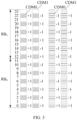
- a DMRS pattern with a single-symbol structure of the first configuration type includes two CDM groups: CDM group 0 and CDM group 1 corresponding to resource elements of different patterns, where CDM group 0 corresponding to resource elements of a diagonal image corresponds to port 0 and port 1, CDM group 1 corresponding to resource elements of a blank pattern corresponds to port 2 and port 3, CDM group 0 corresponding to resource elements of a horizontal-line image corresponds to port 8 and port 9, and CDM group 1 corresponding to resources of a dot image corresponds to port 10 and port 11.
- the first subsequence [+1, +1] is used as a basic unit and mapped to port 0 of the DMRS
- the second subsequence [+1, -1] is used as a basic unit and mapped to port 1
- the first subsequence [+1, +1] and the third subsequence [-1, -1] are used as basic units and mapped to port 8
- the second subsequence [+1, -1] and the fourth subsequence [-1, +1] are used as basic units and mapped to port 9.
- the first subsequence [+1, +1] is mapped to every two adjacent subcarriers occupied by port 0; on port 1, the second subsequence [+1, -1] is mapped to every two adjacent subcarriers occupied by port 1; on port 8, the first subsequence [+1, +1] and the third subsequence [-1, -1] are alternately mapped in the form of the first mapping rule to every two adjacent subcarriers occupied by port 8; and on port 9, the second subsequence [+1, -1] and the fourth subsequence [-1, +1] are alternately mapped in the form of the first mapping rule to every two adjacent subcarriers occupied by port 9.
- FIG. 3 uses two resource blocks (RBs) as an example, but the method is applicable to any quantity of RBs.
- the corresponding second mapping rule may be: sequentially mapping the subsequence with the second length to the subcarriers on the symbol occupied by the port by using the fifth subsequence, the sixth subsequence, the seventh subsequence, or the eighth subsequence as the basic unit respectively.
- the fifth subsequence [+1, +1, +1, +1] is used as a basic unit and mapped to port 0 of the DMRS
- the sixth subsequence [+1, -1, +1, -1] is used as a basic unit and mapped to port 1
- the seventh subsequence [+1, +1, -1, -1] is used as a basic unit and mapped to port 8
- the eighth subsequence [+1, -1, -1, +1] is used as a basic unit and mapped to port 9.
- the four subsequences with the second length are mapped in the form of the second mapping rule to subcarriers 0, 2, 4, and 6 of RB 0; or mapped to subcarriers 8 and 10 of RB 0, and subcarriers 12 and 14 of RB 1, where the mapping is resource mapping in a cross-RB form to resource elements (Resource element, RE) occupied by the DMRS; or mapped to subcarriers 16, 18, 20, and 22 of RB 1.
- FIG. 3 uses two RBs as an example, but the method is applicable to any quantity of RBs.
- the first subsequence [+1, +1] and the second subsequence [+1, -1] are mapped to two adjacent subcarriers with a largest index corresponding to a same CDM group among RBs with the largest index, where the first subsequence [+1, +1] is equivalent to first two elements of the fifth subsequence [+1, +1, +1, +1] and the seventh subsequence [+1, +1, -1, -1]; and the second subsequence [+1, -1] is equivalent to first two elements of the sixth subsequence [+1, -1, +1, -1] and the eighth subsequence [+1, - 1, -1, +1].
- BWP BandWidth Part
- the corresponding second mapping rule may be: sequentially mapping the subsequence with the third length to the subcarriers on the symbol occupied by the port by using the fifth subsequence, the sixth subsequence, the seventh subsequence, or the eighth subsequence as the basic unit respectively.
- the ninth subsequence [+1, +1, +1, +1, +1, +1] is used as a basic unit and mapped to port 0 of the DMRS
- the tenth subsequence [+1, -1, +1, -1, +1, -1] is used as a basic unit and mapped to port 1
- the eleventh subsequence [+1, +1, -1, -1, +1, +1] is used as a basic unit and mapped to port 8
- the twelfth subsequence [+1, -1, -1, +1, +1, -1] is used as a basic unit and mapped to port 9.
- FIG. 3 uses two RBs as an example, but the method is applicable to any quantity of RBs.
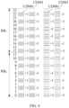
- a DMRS pattern with a single-symbol structure of the second configuration type includes three CDM groups: CDM group 0, CDM group 1, and CDM group 2 corresponding to resource elements of different patterns, where CDM group 0 corresponding to resource elements of a diagonal image corresponds to port 0 and port 1, CDM group 1 corresponding to resource elements of a blank pattern corresponds to port 2 and port 3, CDM group 2 corresponding to resource elements of a vertical-line pattern corresponds to port 4 and port 5, CDM group 0 corresponding to resource elements of a horizontal-line image corresponds to port 12 and port 13, CDM group 1 corresponding to resources of a cross image corresponds to port 14 and port 15, and CDM group 2 corresponding to resources of a point image corresponds to port 16 and port 17.
- the first subsequence [+1, +1] is used as a basic unit and mapped to port 0 of the DMRS
- the second subsequence [+1, -1] is used as a basic unit and mapped to port 1
- the first subsequence [+1, +1] and the third subsequence [-1, -1] are used as basic units and mapped to port 12
- the second subsequence [+1, -1] and the fourth subsequence [-1, +1] are used as basic units and mapped to port 13.
- the first subsequence [+1, +1] is mapped to every two adjacent subcarriers occupied by port 0; on port 1, the second subsequence [+1, -1] is mapped to every two adjacent subcarriers occupied by port 1; on port 12, the first subsequence [+1, +1] and the third subsequence [-1, -1] are alternately mapped in the form of the first mapping rule to every two adjacent subcarriers occupied by port 12; and on port 13, the second subsequence [+1, -1] and the fourth subsequence [-1, +1] are alternately mapped in the form of the first mapping rule to every two adjacent subcarriers occupied by port 13.
- FIG. 5 uses one RB as an example, but the method is applicable to any quantity of RBs.
- the fifth subsequence [+1, +1, +1, +1] is used as a basic unit and mapped to port 0 of the DMRS
- the sixth subsequence [+1, -1, +1, -1] is used as a basic unit and mapped to port 1
- the seventh subsequence [+1, +1, -1, -1] is used as a basic unit and mapped to port 12
- the eighth subsequence [+1, -1, -1, +1] is used as a basic unit and mapped to port 13.
- CDM group 0 the foregoing four subsequences with the second length are mapped in the form of the second mapping rule to four adjacent subcarriers 0, 1, 6, and 7 of RB 0.
- FIG. 5 uses one RB as an example, but the method is applicable to any quantity of RBs.
- the frequency division cover code sequence is generated by using a start subcarrier of a common resource block (Common Resource Block, CRB) with a sequence number of 0 as a start position.
- CRB Common Resource Block
- the start subcarrier is related to a CDM group.
- a frequency division cover code sequence corresponding to CDM group 0 is generated by using a first subcarrier of a common resource block with a sequence number of 0 as a start position; and a frequency division cover code sequence corresponding to CDM group 1 is generated by using a second subcarrier of the common resource block with the sequence number of 0 as a start position.
- a frequency division cover code sequence corresponding to CDM group 0 is generated by using a first subcarrier of a common resource block with a sequence number of 0 as a start position; a frequency division cover code sequence corresponding to CDM group 1 is generated by using a third subcarrier of the common resource block with the sequence number of 0 as a start position; and a frequency division cover code sequence corresponding to CDM group 2 is generated by using a fifth subcarrier of the common resource block with the sequence number of 0 as a start position.
- the target demodulation reference signal is a demodulation reference signal of the first configuration type or the second configuration type, where the first configuration type is related to demodulation reference signal configuration type 1, and the second configuration type is related to demodulation reference signal configuration type 2.
- the target demodulation reference signal is of the first configuration type, where the first configuration type is related to demodulation reference signal configuration type 1.
- up to 8 ports can be supported for the first configuration type and up to 12 ports can be supported for the second configuration type; and for a dual-symbol DMRS, up to 16 ports can be supported for the first configuration type and up to 24 ports can be supported for the second configuration type.
- the quantity has doubled.
- subsequences with a plurality of lengths are designed, and the subsequences are mapped to the port by using the subsequence with the target length as the basic unit, to generate the frequency division cover code sequences and then generate the target DMRS, so that the target DMRS can support more ports and that the transmitted data flows can be increased.
- the method further includes: the terminal receives despreading indication information from the network-side device, where the despreading indication information is used to indicate corresponding despreading window information for the terminal for performing channel estimation on the target demodulation reference signal, and the despreading window information includes a despreading window length.
- the despreading window length may be varied. In this embodiment of this application, only the despreading window length of 2 or 4 is used as an example for description.
- step S220 includes: the terminal performs channel estimation on the target demodulation reference signal based on the despreading window length.
- the terminal performs joint channel estimation by using two adjacent subcarriers occupied by the ports on the symbol as a despreading window.
- the terminal performs joint channel estimation by using four adjacent subcarriers occupied by the ports on the symbol as a despreading window.
- FIG. 6 shows a DMRS pattern with a single-symbol structure of the first configuration type.
- the despreading window length is 4, a channel estimation mode of a DMRS of a terminal is shown in FIG. 6 .
- channel estimation on CDM group 0 as an example, joint channel estimation is performed once in despreading window 1 based on four adjacent subcarriers, and joint channel estimation is performed once in despreading window 2 based on four adjacent subcarriers, that is, channel estimation is performed based on two despreading windows in one RB.
- FIG. 7 shows a DMRS pattern with a single-symbol structure of the second configuration type.
- the despreading window length is 4, a channel estimation mode of a DMRS of a terminal device is shown in FIG. 6 .
- channel estimation on CDM group 0 as an example, joint channel estimation is performed once in despreading window 1 based on four adjacent subcarriers corresponding to CDM group 0.
- frequency division cover codes in the despreading window are orthogonal to each other, four DMRS ports belonging to a same CDM group are orthogonal to each other to ensure performance of channel estimation.
- the frequency division cover codes generated based on the subsequence with the target length as the basic unit can implement code division multiplexing among more DMRS ports, so that a CDM group includes more mutually orthogonal DMRS ports.
- the method before the terminal receives the despreading indication information from the network-side device, the method further includes: the terminal reports a channel estimation capability of the terminal to the network-side device.
- the channel estimation capability is used to indicate whether the terminal supports channel estimation on the demodulation reference signal based on the despreading window length of 4.
- the despreading indication information is sent to the terminal, so that the terminal performs channel estimation on the DMRS based on the despreading window length. Therefore, channel estimation on the target DMRS is more accurate.
- the method further includes: the terminal reports a downlink data receiving capability supported by the terminal to the network-side device, where the downlink data receiving capability includes a capability of a type of a quantity of RBs on a physical downlink shared channel (Physical Downlink Shared Channel, PDSCH) supported by the terminal.
- the downlink data receiving capability includes a capability of a type of a quantity of RBs on a physical downlink shared channel (Physical Downlink Shared Channel, PDSCH) supported by the terminal.
- PDSCH Physical Downlink Shared Channel
- the type of the quantity of RBs on the PDSCH includes one of the following:
- the terminal receives target configuration information from the network-side device, where the target configuration information corresponds to the downlink data receiving capability reported by the terminal, and the target configuration information is used to indicate the type of the quantity of RBs on the PDSCH received by the terminal.
- the network-side device may send target configuration information to indicate to the terminal that quantities of RBs subsequently transmitted on the PDSCH are all even numbers. In this case, the terminal may demodulate the PDSCH by using a corresponding channel estimation method.
- the network-side device may send target configuration information to indicate to the terminal that quantities of RBs subsequently transmitted on the PDSCH are all even numbers or are not limited (that is, the quantities of RBs may be even numbers or odd numbers). In this case, the terminal may demodulate the PDSCH based on the target configuration information by using a corresponding channel estimation method.
- the terminal may perform channel estimation based on two despreading windows in one RB, to resolve a problem of channel estimation when the quantity of RBs on the PDSCH is an odd number.
- the terminal may support that the quantity of RBs on the PDSCH received by the terminal is an odd number.
- channel estimation based on two despreading windows in one RB is only one of channel estimation methods performed by the terminal. Other methods for performing channel estimation on the PDSCH, which may enable the terminal to support an odd number of RBs received by the terminal, are not precluded.
- the type of the quantity of RBs on the PDSCH is determined by the downlink data receiving capability reported by the terminal, so that performance of channel estimation is improved.
- the demodulation reference signal transmission method provided in this embodiment of this application may be performed by a demodulation reference signal transmission apparatus.
- a demodulation reference signal transmission apparatus provided in an embodiment of this application is described by assuming that the demodulation reference signal transmission method in this embodiment of this application is performed by the demodulation reference signal transmission apparatus.
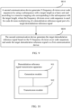
- the demodulation reference signal transmission apparatus includes a transceiver module 701 and a calculation module 702.
- the transceiver module 701 is configured to receive a target demodulation reference signal from a second communication device; and the calculation module 702 is configured to perform channel estimation on the target demodulation reference signal, where the target demodulation reference signal is generated based on N frequency division cover code sequences, the N frequency division cover code sequences are generated based on a subsequence with a target length as a basic unit and according to a resource mapping rule corresponding to the subsequence with the target length, the frequency division cover code sequence is used for code division multiplexing of a port of the target demodulation reference signal, and N is a positive integer.
- the N frequency division cover code sequences are generated based on the subsequence with the target length as the basic unit and according to the resource mapping rule corresponding to the subsequence with the target length; and the target demodulation reference signal is generated based on the N frequency division cover code sequences, and sent for channel estimation, so that the target DMRS can support more ports and that transmitted data flows can be increased.
- the subsequence with the target length is one of the following:
- frequency division cover code sequence is generated in one of the following manners:
- subsequence with the first length is at least one of the following:
- subsequence with the second length is at least one of the following:
- subsequence with the third length is at least one of the following:
- the first mapping rule is to alternately map the first subsequence and the third subsequence to subcarriers on the symbol occupied by the port.
- the first mapping rule is to alternately map the second subsequence and the fourth subsequence to subcarriers on the symbol occupied by the port.
- the frequency division cover code sequence is generated by using a start subcarrier of a common resource block with a sequence number of 0 as a start position.
- the target demodulation reference signal is a demodulation reference signal of a first configuration type or a second configuration type, where the first configuration type is related to demodulation reference signal configuration type 1, and the second configuration type is related to demodulation reference signal configuration type 2.
- the target demodulation reference signal is of a first configuration type, where the first configuration type is related to demodulation reference signal configuration type 1.
- subsequences with a plurality of lengths are designed, and the subsequences are mapped to the port by using the subsequence with the target length as the basic unit, to generate the frequency division cover code sequences and then generate the target DMRS, so that the target DMRS can support more ports and that the transmitted data flows can be increased.
- the transceiver module 701 is further configured to: receive despreading indication information from the network-side device, where the despreading indication information is used to indicate corresponding despreading window information for the terminal for performing channel estimation on the target demodulation reference signal, and the despreading window information includes a despreading window length.
- calculation module 702 is configured to perform channel estimation on the target demodulation reference signal based on the despreading window length.
- despreading window length is 2 or 4.
- calculation module 702 is configured to perform at least one of the following:
- the transceiver module 701 is further configured to report a channel estimation capability of the terminal to the network-side device.
- the channel estimation capability is used to indicate whether the terminal supports channel estimation on the demodulation reference signal based on the despreading window length of 4.
- the despreading indication information is sent to the terminal, so that the terminal performs channel estimation on the DMRS based on the despreading window length. Therefore, channel estimation on the target DMRS is more accurate.
- the transceiver module 701 is further configured to report a downlink data receiving capability supported by the terminal to the network-side device, where the downlink data receiving capability includes a capability of a type of a quantity of RBs on a PDSCH supported by the terminal.
- the type of the quantity of RBs on the PDSCH includes one of the following:
- the transceiver module 701 is further configured to receive target configuration information from the network-side device, where the target configuration information corresponds to the downlink data receiving capability reported by the terminal, and the target configuration information is used to indicate the type of the quantity of RBs on the PDSCH received by the terminal.
- the type of the quantity of RBs on the PDSCH is determined by the downlink data receiving capability reported by the terminal, so that performance of channel estimation is improved.
- the demodulation reference signal transmission apparatus in this embodiment of this application may be an electronic device, for example, an electronic device with an operating system, or may be a component in an electronic device, for example, an integrated circuit or a chip.
- the electronic device may be a terminal, or may be other devices than a terminal.
- the terminal may include but is not limited to the foregoing illustrated type of the terminal 11.
- the other devices may be a server, a network attached storage (Network Attached Storage, NAS), and the like. This is not specifically limited in this embodiment of this application.
- the demodulation reference signal transmission apparatus provided in this embodiment of this application can implement each process implemented in the method embodiments in FIG. 2 to FIG. 7 , with the same technical effect achieved. To avoid repetition, details are not described herein again.
- an embodiment of this application provides a demodulation reference signal transmission method.
- the method is performed by a second communication device.
- the second communication device may be a network-side device or a terminal.
- the method may be performed by software or hardware installed in the second communication device.
- the method includes the following steps.
- the second communication device generates N frequency division cover code sequences by using a subsequence with a target length as a basic unit and according to a resource mapping rule corresponding to the subsequence with the target length, where the frequency division cover code sequence is used for code division multiplexing of a demodulation reference signal port of a target demodulation reference signal.
- the second communication device generates the target demodulation reference signal based on the N frequency division cover code sequences, and sends the target demodulation reference signal to a first communication device, where N is a positive integer.
- Steps S810 and S820 can implement the method embodiment shown in FIG. 2 , with the same technical effect achieved. To avoid repetition, details are not described herein again.
- the N frequency division cover code sequences are generated based on the subsequence with the target length as the basic unit and according to the resource mapping rule corresponding to the subsequence with the target length; and the target demodulation reference signal is generated based on the N frequency division cover code sequences, and sent for channel estimation, so that the target DMRS can support more ports and that transmitted data flows can be increased.
- the subsequence with the target length is one of the following:
- step S810 includes one of the following manners:
- subsequence with the first length is at least one of the following:
- subsequence with the second length is at least one of the following:
- subsequence with the third length is at least one of the following:
- the first mapping rule is to alternately map the first subsequence and the third subsequence to subcarriers on the symbol occupied by the port.
- the first mapping rule is to alternately map the second subsequence and the fourth subsequence to subcarriers on the symbol occupied by the port.
- the frequency division cover code sequence is generated by using a start subcarrier of a common resource block with a sequence number of 0 as a start position.
- the target demodulation reference signal is a demodulation reference signal of a first configuration type or a second configuration type, where the first configuration type is related to demodulation reference signal configuration type 1, and the second configuration type is related to demodulation reference signal configuration type 2.
- the demodulation reference signal is of a first configuration type, where the first configuration type is related to demodulation reference signal configuration type 1.
- subsequences with a plurality of lengths are designed, and the subsequences are mapped to the port by using the subsequence with the target length as the basic unit, to generate the frequency division cover code sequences and then generate the target DMRS, so that the target DMRS can support more ports and that the transmitted data flows can be increased.
- the method further includes: the network-side device sends despreading indication information to the terminal, where the despreading indication information is used to indicate corresponding despreading window information for the terminal for performing channel estimation on the target demodulation reference signal, and the despreading window information includes a despreading window length.
- despreading window length is 2 or 4.
- the method further includes: the network-side device receives a channel estimation capability of the terminal from the terminal.
- the channel estimation capability is used to indicate whether the terminal supports channel estimation on the demodulation reference signal based on the despreading window length of 4.
- the despreading indication information is sent to the terminal, so that the terminal performs channel estimation on the DMRS based on the despreading window length. Therefore, channel estimation on the target DMRS is more accurate.
- the method further includes: the network-side device receives from the terminal, a downlink data receiving capability supported by the terminal, where the downlink data receiving capability includes a capability of a type of a quantity of RBs on a PDSCH supported by the terminal.
- the type of the quantity of RBs on the PDSCH includes one of the following:
- the network-side device sends target configuration information to the terminal, where the target configuration information corresponds to the downlink data receiving capability supported by the terminal and received by the network-side device from the terminal, and the target configuration information is used to indicate the type of the quantity of RBs on the PDSCH received by the terminal.
- the demodulation reference signal transmission method provided in this embodiment of this application may be performed by a demodulation reference signal transmission apparatus.
- a demodulation reference signal transmission apparatus provided in an embodiment of this application is described by assuming that the demodulation reference signal transmission method in this embodiment of this application is performed by the demodulation reference signal transmission apparatus.
- the demodulation reference signal transmission apparatus includes a generation module 901 and a transmission module 902.
- the generation module 901 is configured to generate N frequency division cover code sequences by using a subsequence with a target length as a basic unit and according to a resource mapping rule corresponding to the subsequence with the target length, where the frequency division cover code sequence is used for code division multiplexing of a demodulation reference signal port of a target demodulation reference signal; and the transmission module 902 is configured to generate the target demodulation reference signal based on the N frequency division cover code sequences, and send the target demodulation reference signal to a first communication device, where N is a positive integer.
- the N frequency division cover code sequences are generated based on the subsequence with the target length as the basic unit and according to the resource mapping rule corresponding to the subsequence with the target length; and the target demodulation reference signal is generated based on the N frequency division cover code sequences, and sent for channel estimation, so that the target DMRS can support more ports and that transmitted data flows can be increased.
- the subsequence with the target length is one of the following:
- the generation module 901 is configured to perform one of the following manners:
- subsequence with the first length is at least one of the following:
- subsequence with the second length is at least one of the following:
- subsequence with the third length is at least one of the following:
- the first mapping rule is to alternately map the first subsequence and the third subsequence to subcarriers on the symbol occupied by the port.
- the first mapping rule is to alternately map the second subsequence and the fourth subsequence to subcarriers on the symbol occupied by the port.
- the frequency division cover code sequence is generated by using a start subcarrier of a common resource block with a sequence number of 0 as a start position.
- the target demodulation reference signal is a demodulation reference signal of a first configuration type or a second configuration type, where the first configuration type is related to demodulation reference signal configuration type 1, and the second configuration type is related to demodulation reference signal configuration type 2.
- the demodulation reference signal is of a first configuration type, where the first configuration type is related to demodulation reference signal configuration type 1.
- subsequences with a plurality of lengths are designed, and the subsequences are mapped to the port by using the subsequence with the target length as the basic unit, to generate the frequency division cover code sequences and then generate the target DMRS, so that the target DMRS can support more ports and that the transmitted data flows can be increased.
- the transmission module 902 is further configured to send despreading indication information to the terminal, where the despreading indication information is used to indicate corresponding despreading window information for the terminal for performing channel estimation on the target demodulation reference signal, and the despreading window information includes a despreading window length.
- despreading window length is 2 or 4.
- the transmission module 902 is further configured to receive a channel estimation capability of the terminal from the terminal.
- the channel estimation capability is used to indicate whether the terminal supports channel estimation on the demodulation reference signal based on the despreading window length of 4.
- the despreading indication information is sent to the terminal, so that the terminal performs channel estimation on the DMRS based on the despreading window length. Therefore, channel estimation on the target DMRS is more accurate.
- the transmission module 902 is further configured to receive a downlink data receiving capability supported by the terminal, where the downlink data receiving capability includes a capability of a type of a quantity of RBs on a physical downlink shared channel PDSCH supported by the terminal.
- the type of the quantity of RBs on the PDSCH includes one of the following:
- the transmission module 902 is further configured to send target configuration information to the terminal, where the target configuration information corresponds to the downlink data receiving capability supported by the terminal and received by the network-side device from the terminal, and the target configuration information is used to indicate the type of the quantity of RBs on the PDSCH received by the terminal.
- the demodulation reference signal transmission apparatus in this embodiment of this application may be an electronic device, for example, an electronic device with an operating system, or may be a component in an electronic device, for example, an integrated circuit or a chip.
- the electronic device may be a terminal, or may be other devices than a terminal.
- the terminal may include but is not limited to the foregoing illustrated type of the terminal 11.
- the other devices may be a server, a network attached storage (Network Attached Storage, NAS), and the like. This is not specifically limited in this embodiment of this application.
- the demodulation reference signal transmission apparatus provided in this embodiment of this application can implement each process implemented in the method embodiment in FIG. 9 , with the same technical effect achieved. To avoid repetition, details are not described herein again.
- an embodiment of this application further provides a communication device 1000, including a processor 1001 and a memory 1002.
- the memory 1002 stores a program or instructions capable of running on the processor 1001.
- the steps of the foregoing embodiment of the demodulation reference signal transmission method are implemented, with the same technical effect achieved.
- the communication device 1000 is a network-side device, and the program or instructions are executed by the processor 1001, the steps of the foregoing embodiment of the demodulation reference signal transmission method are implemented, with the same technical effect achieved. To avoid repetition, details are not described herein again.
- An embodiment of this application further provides a terminal, including a processor and a communication interface.
- the communication interface is configured to receive a target demodulation reference signal from a second communication device, and the processor is configured to perform channel estimation on the target demodulation reference signal.
- the terminal embodiment corresponds to the foregoing terminal-side method embodiment, and each implementation process and implementation of the foregoing method embodiment can be applied to the terminal embodiment, with the same technical effect achieved.
- FIG. 12 is a schematic diagram of a hardware structure of a terminal for implementing an embodiment of this application.
- the terminal 1100 includes but is not limited to at least some components such as a radio frequency unit 1101, a network module 1102, an audio output unit 1103, an input unit 1104, a sensor 1105, a display unit 1106, a user input unit 1107, an interface unit 1108, a memory 1109, and a processor 1110.
- the terminal 1100 may further include a power supply (for example, a battery) supplying power to all components.
- the power supply may be logically connected to the processor 1110 through a power management system. In this way, functions such as charge management, discharge management, and power consumption management are implemented by using the power management system.
- the terminal structure shown in FIG. 12 does not constitute a limitation on the terminal.
- the terminal may include more or fewer components than those shown in the figure, or some components are combined, or component arrangements are different. Details are not described herein again.
- the input unit 1104 may include a graphics processing unit (Graphics Processing Unit, GPU) 11041 and a microphone 11042.
- the GPU 11041 processes image data of a still picture or video obtained by an image capture apparatus (such as a camera) in a video capture mode or an image capture mode.
- the display unit 1106 may include a display panel 11061, and the display panel 11061 may be configured in a form of a liquid crystal display, an organic light-emitting diode, or the like.
- the user input unit 1107 includes at least one of a touch panel 11071 and other input devices 11072.
- the touch panel 11071 is also referred to as a touchscreen.
- the touch panel 11071 may include two parts: a touch detection apparatus and a touch controller.
- the other input devices 11072 may include but are not limited to a physical keyboard, a function button (such as a volume control button or a power button), a trackball, a mouse, and a joystick. Details are not described herein again.
- the radio frequency unit 1101 may transmit the downlink data to the processor 1110 for processing.
- the radio frequency unit 1101 may send uplink data to the network-side device.
- the radio frequency unit 1101 includes but is not limited to an antenna, an amplifier, a transceiver, a coupler, a low noise amplifier, a duplexer, and the like.
- the memory 1109 may be configured to store software programs or instructions and various data.
- the memory 1109 may primarily include a first storage area for storing programs or instructions and a second storage area for storing data.
- the first storage area may store an operating system, an application program or instructions required by at least one function (such as an audio play function and an image play function), and the like.
- the memory 1109 may include a volatile memory or a non-volatile memory, or the memory 1109 may include both a volatile memory and a non-volatile memory.
- the non-volatile memory may be a read-only memory (Read-Only Memory, ROM), a programmable read-only memory (Programmable ROM, PROM), an erasable programmable read-only memory (Erasable PROM, EPROM), an electrically erasable programmable read-only memory (Electrically EPROM, EEPROM), or a flash memory.
- ROM Read-Only Memory
- PROM programmable read-only memory
- Erasable PROM Erasable PROM
- EPROM electrically erasable programmable read-only memory
- EEPROM electrically erasable programmable read-only memory
- the volatile memory may be a random access memory (Random Access Memory, RAM), a static random access memory (Static RAM, SRAM), a dynamic random access memory (Dynamic RAM, DRAM), a synchronous dynamic random access memory (Synchronous DRAM, SDRAM), a double data rate synchronous dynamic random access memory (Double Data Rate SDRAM, DDR SDRAM), an enhanced synchronous dynamic random access memory (Enhanced SDRAM, ESDRAM), a synchlink dynamic random access memory (Synch Link DRAM, SLDRAM), and a direct rambus random access memory (Direct Rambus RAM, DRRAM).
- RAM Random Access Memory
- SRAM static random access memory
- DRAM dynamic random access memory
- DRAM synchronous dynamic random access memory
- SDRAM double data rate synchronous dynamic random access memory
- Enhanced SDRAM, ESDRAM enhanced synchronous dynamic random access memory
- Synch Link DRAM Synchlink dynamic random access memory
- SLDRAM direct rambus random access memory
- Direct Rambus RAM Direct Rambus RAM,
- the processor 1110 may include one or more processing units.
- the processor 1110 integrates an application processor and a modem processor.
- the application processor mainly processes operations related to the operating system, a user interface, an application program, and the like.
- the modem processor mainly processes a wireless communication signal.
- the modem processor is a baseband processor. It may be understood that the modem processor may alternatively be not integrated in the processor 1110.
- the radio frequency unit 1101 is configured to receive a target demodulation reference signal from a second communication device.
- the N frequency division cover code sequences are generated based on the subsequence with the target length as the basic unit and according to the resource mapping rule corresponding to the subsequence with the target length; and the target demodulation reference signal is generated based on the N frequency division cover code sequences, and sent for channel estimation, so that the target DMRS can support more ports and that transmitted data flows can be increased.
- the subsequence with the target length is one of the following:
- frequency division cover code sequence is generated in one of the following manners:
- subsequence with the first length is at least one of the following:
- subsequence with the second length is at least one of the following:
- subsequence with the third length is at least one of the following:
- the first mapping rule is to alternately map the first subsequence and the third subsequence to subcarriers on the symbol occupied by the port.
- the first mapping rule is to alternately map the second subsequence and the fourth subsequence to subcarriers on the symbol occupied by the port.
- the frequency division cover code sequence is generated by using a start subcarrier of a common resource block with a sequence number of 0 as a start position.
- the target demodulation reference signal is a demodulation reference signal of a first configuration type or a second configuration type, where the first configuration type is related to demodulation reference signal configuration type 1, and the second configuration type is related to demodulation reference signal configuration type 2.
- the target demodulation reference signal is of a first configuration type, where the first configuration type is related to demodulation reference signal configuration type 1.
- This embodiment of this application enables the target DMRS to support more ports and increase transmitted data flows.
- the radio frequency unit 1101 is further configured to: receive despreading indication information from the network-side device, where the despreading indication information is used to indicate corresponding despreading window information for the terminal for performing channel estimation on the target demodulation reference signal, and the despreading window information includes a despreading window length.
- the processor 1110 is configured to perform channel estimation on the target demodulation reference signal based on the despreading window length.
- despreading window length is 2 or 4.
- processor 1110 is configured to perform at least one of the following:
- the radio frequency unit 1101 is further configured to report a channel estimation capability of the terminal to the network-side device.
- the channel estimation capability is used to indicate whether the terminal supports channel estimation on the demodulation reference signal based on the despreading window length of 4.
- the radio frequency unit 1101 is further configured to report a downlink data receiving capability supported by the terminal to the network-side device, where the downlink data receiving capability includes a capability of a type of a quantity of RBs on a physical downlink shared channel PDSCH supported by the terminal.
- the type of the quantity of RBs on the PDSCH includes one of the following:
- the radio frequency unit 1101 is further configured to receive target configuration information from the network-side device, where the target configuration information corresponds to the downlink data receiving capability reported by the terminal, and the target configuration information is used to indicate the type of the quantity of RBs on the PDSCH received by the terminal.
- This embodiment of this application enables channel estimation on the target DMRS to be more accurate.
- An embodiment of this application further provides a network-side device, including a processor and a communication interface.
- the processor is configured to generate N frequency division cover code sequences by using a subsequence with a target length as a basic unit and according to a resource mapping rule corresponding to the subsequence with the target length, where the frequency division cover code sequence is used for code division multiplexing of a demodulation reference signal port of a target demodulation reference signal; and the communication interface is configured to generate the target demodulation reference signal based on the N frequency division cover code sequences, and send the target demodulation reference signal to a first communication device.
- the network-side device embodiment corresponds to the foregoing method embodiment of the network-side device, and each implementation process and implementation of the foregoing method embodiment can be applied to the network-side device embodiment, with the same technical effect achieved.
- the network-side device 1200 includes an antenna 121, a radio frequency apparatus 122, a baseband apparatus 123, a processor 124, and a memory 125.
- the antenna 121 is connected to the radio frequency apparatus 122.
- the radio frequency apparatus 122 receives information by using the antenna 121, and sends the received information to the baseband apparatus 123 for processing.
- the baseband apparatus 123 processes to-be-sent information, and sends the information to the radio frequency apparatus 122; and the radio frequency apparatus 122 processes the received information and then sends the information out by using the antenna 121.
- the method performed by the network-side device in the foregoing embodiment may be implemented in the baseband apparatus 123.
- the baseband apparatus 123 includes a baseband processor.
- the baseband apparatus 123 may include, for example, at least one baseband unit, where a plurality of chips are disposed on the baseband unit. As shown in FIG. 13 , one of the chips is, for example, the baseband processor, connected to the memory 125 by using a bus interface, to invoke a program in the memory 125 to perform the operation of the network device shown in the foregoing method embodiment.
- the network-side device may further include a network interface 126, where the interface is, for example, a common public radio interface (common public radio interface, CPRI).
- a common public radio interface common public radio interface, CPRI
- the network-side device 1200 in this embodiment of the present invention further includes a program or instructions stored in the memory 125 and capable of running on the processor 124.
- the processor 124 invokes the program or instructions in the memory 125, the method performed by each module shown in FIG. 7 is performed, with the same technical effect achieved. To avoid repetition, details are not described herein again.
- An embodiment of this application further provides a readable storage medium.
- the readable storage medium stores a program or instructions.
- the program or instructions are executed by a processor, each process of the foregoing embodiment of the demodulation reference signal transmission method is implemented, with the same technical effect achieved. To avoid repetition, details are not described herein again.
- the processor is a processor in the terminal in the foregoing embodiment.
- the readable storage medium includes a computer-readable storage medium, such as a computer read-only memory ROM, a random access memory RAM, a magnetic disk, or an optical disc.
- an embodiment of this application provides a chip.
- the chip includes a processor and a communication interface.
- the communication interface is coupled to the processor.
- the processor is configured to run a program or instructions to implement each process of the embodiment of the demodulation reference signal transmission method, with the same technical effect achieved. To avoid repetition, details are not described herein again.
- the chip provided in this embodiment of this application may also be referred to as a system-level chip, a system chip, a chip system, a system-on-chip, or the like.
- an embodiment of this application provides a computer program or program product.
- the computer program or program product is stored in a storage medium.
- the computer program or program product is executed by at least one processor to implement each process of the foregoing demodulation reference signal transmission method embodiment, with the same technical effect achieved. To avoid repetition, details are not described herein again.
- An embodiment of this application further provides a demodulation reference signal transmission system, including a terminal and a network-side device.
- the terminal may be configured to perform the steps of the foregoing demodulation reference signal transmission method.
- the network-side device may be configured to perform the steps of the foregoing demodulation reference signal transmission method.
- the computer software product is stored in a storage medium (such as a ROM/RAM, a magnetic disk, or an optical disc), and includes several instructions for instructing a terminal (which may be a mobile phone, a computer, a server, an air conditioner, a network device, or the like) to perform the methods described in the embodiments of this application.
- a storage medium such as a ROM/RAM, a magnetic disk, or an optical disc
- a terminal which may be a mobile phone, a computer, a server, an air conditioner, a network device, or the like
Landscapes
- Engineering & Computer Science (AREA)
- Signal Processing (AREA)
- Computer Networks & Wireless Communication (AREA)
- Databases & Information Systems (AREA)
- Power Engineering (AREA)
- Mobile Radio Communication Systems (AREA)
Applications Claiming Priority (3)
| Application Number | Priority Date | Filing Date | Title |
|---|---|---|---|
| CN202210346947 | 2022-04-02 | ||
| CN202211103762.5A CN116896432A (zh) | 2022-04-02 | 2022-09-09 | 解调参考信号传输方法、装置、终端及网络侧设备 |
| PCT/CN2023/085801 WO2023186158A1 (fr) | 2022-04-02 | 2023-03-31 | Procédé et appareil de transmission de signal de référence de démodulation, terminal et dispositif côté réseau |
Publications (2)
| Publication Number | Publication Date |
|---|---|
| EP4507426A1 true EP4507426A1 (fr) | 2025-02-12 |
| EP4507426A4 EP4507426A4 (fr) | 2025-07-30 |
Family
ID=88199467
Family Applications (1)
| Application Number | Title | Priority Date | Filing Date |
|---|---|---|---|
| EP23778522.5A Pending EP4507426A4 (fr) | 2022-04-02 | 2023-03-31 | Procédé et appareil de transmission de signal de référence de démodulation, terminal et dispositif côté réseau |
Country Status (5)
| Country | Link |
|---|---|
| US (1) | US20250023686A1 (fr) |
| EP (1) | EP4507426A4 (fr) |
| JP (1) | JP2025512932A (fr) |
| KR (1) | KR20240170949A (fr) |
| WO (1) | WO2023186158A1 (fr) |
Families Citing this family (1)
| Publication number | Priority date | Publication date | Assignee | Title |
|---|---|---|---|---|
| JP2025516224A (ja) * | 2022-04-28 | 2025-05-27 | アップル インコーポレイテッド | Cdmグループ拡張を伴うdmrs設計 |
Family Cites Families (9)
| Publication number | Priority date | Publication date | Assignee | Title |
|---|---|---|---|---|
| WO2016127309A1 (fr) * | 2015-02-10 | 2016-08-18 | Qualcomm Incorporated | Amélioration du signal de référence de démodulation pour un système mimo-mu d'ordre supérieur |
| US10469225B2 (en) * | 2015-09-14 | 2019-11-05 | Lg Electronics Inc. | Method for transmitting and receiving demodulation reference signal, and apparatus using same |
| KR102375473B1 (ko) * | 2017-03-23 | 2022-03-17 | 주식회사 아이티엘 | Nr 시스템을 위한 복조 참조신호 패턴 설정 정보 송수신 방법 및 장치 |
| CN110166194B (zh) * | 2018-02-12 | 2020-09-08 | 华为技术有限公司 | 一种导频信号生成方法及装置 |
| CN111416692B (zh) * | 2019-01-07 | 2023-05-09 | 中国移动通信有限公司研究院 | 一种配置方法及设备 |
| CN111277383A (zh) * | 2019-02-15 | 2020-06-12 | 维沃移动通信有限公司 | 参考信号生成的方法及通信设备 |
| CN112104444B (zh) * | 2019-06-17 | 2022-04-08 | 中国移动通信有限公司研究院 | 参考信号的发送方法、终端及网络侧设备 |
| WO2021024329A1 (fr) * | 2019-08-02 | 2021-02-11 | 株式会社Nttドコモ | Terminal et procédé de communication sans fil |
| MX2024005509A (es) * | 2022-01-28 | 2024-05-23 | Zte Corp | Sistemas y metodos para configuracion e indicacion de puertos dmrs. |
-
2023
- 2023-03-31 JP JP2024558471A patent/JP2025512932A/ja active Pending
- 2023-03-31 KR KR1020247036739A patent/KR20240170949A/ko active Pending
- 2023-03-31 WO PCT/CN2023/085801 patent/WO2023186158A1/fr not_active Ceased
- 2023-03-31 EP EP23778522.5A patent/EP4507426A4/fr active Pending
-
2024
- 2024-10-01 US US18/903,157 patent/US20250023686A1/en active Pending
Also Published As
| Publication number | Publication date |
|---|---|
| KR20240170949A (ko) | 2024-12-05 |
| US20250023686A1 (en) | 2025-01-16 |
| EP4507426A4 (fr) | 2025-07-30 |
| WO2023186158A1 (fr) | 2023-10-05 |
| JP2025512932A (ja) | 2025-04-22 |
Similar Documents
| Publication | Publication Date | Title |
|---|---|---|
| US20250220647A1 (en) | Resource configuration method and apparatus, and terminal and network side device | |
| US20250056625A1 (en) | Terminal operation method and apparatus, terminal, and network-side device | |
| CN115150951B (zh) | 传输方向的确定方法、装置、终端及网络侧设备 | |
| CN116367312B (zh) | 传输确定方法、装置、终端、网络侧设备和存储介质 | |
| EP4462713A1 (fr) | Procédé de mappage de ports de signal de référence de sondage, et terminal | |
| EP4373174A1 (fr) | Procédé et appareil de détermination d'état tci, et terminal et dispositif côté réseau | |
| CN117479238A (zh) | 条件配置信息的处理方法、装置及通信设备 | |
| US20250023686A1 (en) | Demodulation Reference Signal Transmission Method and Apparatus, Terminal, and Network-Side Device | |
| EP4422291A1 (fr) | Procédé de rapport d'informations, procédé de réception d'informations, et terminal, dispositif côté réseau et support de stockage | |
| US20250343655A1 (en) | Phase tracking reference signal transmission method and apparatus, terminal, and network-side device | |
| CN116896432A (zh) | 解调参考信号传输方法、装置、终端及网络侧设备 | |
| US20250261202A1 (en) | Method for common pucch transmission with repetitions, terminal, and network-side device | |
| US20250016590A1 (en) | Information sending method, information receiving method, sending end, and receiving end | |
| US20240380551A1 (en) | DMRS Generation Method, and Terminal and Network-Side Device | |
| EP4460108A1 (fr) | Procédé d'exécution d'opération de communication, appareil, terminal et support de stockage | |
| CN116846523A (zh) | Dmrs传输方法、装置及相关设备 | |
| CN116938426A (zh) | Dmrs端口信息的指示方法、终端及网络侧设备 | |
| CN116707725A (zh) | 解调参考信号映射方法、装置、通信设备及存储介质 | |
| US20240413949A1 (en) | Demodulation reference signal information determining method and indication method, and related device | |
| EP4507228A1 (fr) | Procédé d'indication d'informations de port dmrs, terminal et dispositif côté réseau | |
| EP4301068A1 (fr) | Procédé et dispositif pour indiquer des scs de bwp de liaison descendante initiale | |
| US20260032711A1 (en) | Mapping Resource Determination Method, User Equipment, and Non-Transitory Readable Storage Medium | |
| EP4661545A1 (fr) | Procédé de détermination de taille de dci, procédé d'envoi de dci, appareil et dispositif associé | |
| US20250379684A1 (en) | Method for determining harq process id, terminal, and network side device | |
| EP4598105A1 (fr) | Procédé et appareil de rapport d'informations d'intervalle, et dispositif de communication, système et support d'enregistrement |
Legal Events
| Date | Code | Title | Description |
|---|---|---|---|
| STAA | Information on the status of an ep patent application or granted ep patent |
Free format text: STATUS: THE INTERNATIONAL PUBLICATION HAS BEEN MADE |
|
| PUAI | Public reference made under article 153(3) epc to a published international application that has entered the european phase |
Free format text: ORIGINAL CODE: 0009012 |
|
| STAA | Information on the status of an ep patent application or granted ep patent |
Free format text: STATUS: REQUEST FOR EXAMINATION WAS MADE |
|
| 17P | Request for examination filed |
Effective date: 20241101 |
|
| AK | Designated contracting states |
Kind code of ref document: A1 Designated state(s): AL AT BE BG CH CY CZ DE DK EE ES FI FR GB GR HR HU IE IS IT LI LT LU LV MC ME MK MT NL NO PL PT RO RS SE SI SK SM TR |
|
| DAV | Request for validation of the european patent (deleted) | ||
| DAX | Request for extension of the european patent (deleted) | ||
| A4 | Supplementary search report drawn up and despatched |
Effective date: 20250626 |
|
| RIC1 | Information provided on ipc code assigned before grant |
Ipc: H04W 72/04 20230101AFI20250620BHEP Ipc: H04L 27/26 20060101ALI20250620BHEP |