EP4508968A1 - Tondeuse automatique - Google Patents
Tondeuse automatique Download PDFInfo
- Publication number
- EP4508968A1 EP4508968A1 EP23787673.5A EP23787673A EP4508968A1 EP 4508968 A1 EP4508968 A1 EP 4508968A1 EP 23787673 A EP23787673 A EP 23787673A EP 4508968 A1 EP4508968 A1 EP 4508968A1
- Authority
- EP
- European Patent Office
- Prior art keywords
- distance
- field
- lawn mower
- image acquisition
- acquisition apparatus
- Prior art date
- Legal status (The legal status is an assumption and is not a legal conclusion. Google has not performed a legal analysis and makes no representation as to the accuracy of the status listed.)
- Pending
Links
Images


Classifications
-
- A—HUMAN NECESSITIES
- A01—AGRICULTURE; FORESTRY; ANIMAL HUSBANDRY; HUNTING; TRAPPING; FISHING
- A01D—HARVESTING; MOWING
- A01D34/00—Mowers; Mowing apparatus of harvesters
- A01D34/01—Mowers; Mowing apparatus of harvesters characterised by features relating to the type of cutting apparatus
- A01D34/412—Mowers; Mowing apparatus of harvesters characterised by features relating to the type of cutting apparatus having rotating cutters
- A01D34/63—Mowers; Mowing apparatus of harvesters characterised by features relating to the type of cutting apparatus having rotating cutters having cutters rotating about a vertical axis
- A01D34/64—Mowers; Mowing apparatus of harvesters characterised by features relating to the type of cutting apparatus having rotating cutters having cutters rotating about a vertical axis mounted on a vehicle, e.g. a tractor, or drawn by an animal or a vehicle
-
- A—HUMAN NECESSITIES
- A01—AGRICULTURE; FORESTRY; ANIMAL HUSBANDRY; HUNTING; TRAPPING; FISHING
- A01D—HARVESTING; MOWING
- A01D34/00—Mowers; Mowing apparatus of harvesters
- A01D34/006—Control or measuring arrangements
- A01D34/008—Control or measuring arrangements for automated or remotely controlled operation
-
- A—HUMAN NECESSITIES
- A01—AGRICULTURE; FORESTRY; ANIMAL HUSBANDRY; HUNTING; TRAPPING; FISHING
- A01D—HARVESTING; MOWING
- A01D34/00—Mowers; Mowing apparatus of harvesters
- A01D34/006—Control or measuring arrangements
-
- A—HUMAN NECESSITIES
- A01—AGRICULTURE; FORESTRY; ANIMAL HUSBANDRY; HUNTING; TRAPPING; FISHING
- A01D—HARVESTING; MOWING
- A01D75/00—Accessories for harvesters or mowers
- A01D75/18—Safety devices for parts of the machines
- A01D75/185—Avoiding collisions with obstacles
-
- G—PHYSICS
- G01—MEASURING; TESTING
- G01S—RADIO DIRECTION-FINDING; RADIO NAVIGATION; DETERMINING DISTANCE OR VELOCITY BY USE OF RADIO WAVES; LOCATING OR PRESENCE-DETECTING BY USE OF THE REFLECTION OR RERADIATION OF RADIO WAVES; ANALOGOUS ARRANGEMENTS USING OTHER WAVES
- G01S17/00—Systems using the reflection or reradiation of electromagnetic waves other than radio waves, e.g. lidar systems
- G01S17/88—Lidar systems specially adapted for specific applications
- G01S17/93—Lidar systems specially adapted for specific applications for anti-collision purposes
- G01S17/931—Lidar systems specially adapted for specific applications for anti-collision purposes of land vehicles
-
- G—PHYSICS
- G05—CONTROLLING; REGULATING
- G05D—SYSTEMS FOR CONTROLLING OR REGULATING NON-ELECTRIC VARIABLES
- G05D1/00—Control of position, course, altitude or attitude of land, water, air or space vehicles, e.g. using automatic pilots
- G05D1/20—Control system inputs
- G05D1/24—Arrangements for determining position or orientation
- G05D1/243—Means capturing signals occurring naturally from the environment, e.g. ambient optical, acoustic, gravitational or magnetic signals
-
- G—PHYSICS
- G05—CONTROLLING; REGULATING
- G05D—SYSTEMS FOR CONTROLLING OR REGULATING NON-ELECTRIC VARIABLES
- G05D1/00—Control of position, course, altitude or attitude of land, water, air or space vehicles, e.g. using automatic pilots
- G05D1/60—Intended control result
- G05D1/617—Safety or protection, e.g. defining protection zones around obstacles or avoiding hazards
- G05D1/622—Obstacle avoidance
-
- G—PHYSICS
- G06—COMPUTING OR CALCULATING; COUNTING
- G06V—IMAGE OR VIDEO RECOGNITION OR UNDERSTANDING
- G06V10/00—Arrangements for image or video recognition or understanding
- G06V10/10—Image acquisition
- G06V10/12—Details of acquisition arrangements; Constructional details thereof
-
- G—PHYSICS
- G06—COMPUTING OR CALCULATING; COUNTING
- G06V—IMAGE OR VIDEO RECOGNITION OR UNDERSTANDING
- G06V20/00—Scenes; Scene-specific elements
- G06V20/50—Context or environment of the image
- G06V20/56—Context or environment of the image exterior to a vehicle by using sensors mounted on the vehicle
- G06V20/58—Recognition of moving objects or obstacles, e.g. vehicles or pedestrians; Recognition of traffic objects, e.g. traffic signs, traffic lights or roads
-
- H—ELECTRICITY
- H04—ELECTRIC COMMUNICATION TECHNIQUE
- H04N—PICTORIAL COMMUNICATION, e.g. TELEVISION
- H04N23/00—Cameras or camera modules comprising electronic image sensors; Control thereof
- H04N23/60—Control of cameras or camera modules
- H04N23/695—Control of camera direction for changing a field of view, e.g. pan, tilt or based on tracking of objects
-
- A—HUMAN NECESSITIES
- A01—AGRICULTURE; FORESTRY; ANIMAL HUSBANDRY; HUNTING; TRAPPING; FISHING
- A01D—HARVESTING; MOWING
- A01D2101/00—Lawn-mowers
-
- G—PHYSICS
- G05—CONTROLLING; REGULATING
- G05D—SYSTEMS FOR CONTROLLING OR REGULATING NON-ELECTRIC VARIABLES
- G05D2105/00—Specific applications of the controlled vehicles
- G05D2105/15—Specific applications of the controlled vehicles for harvesting, sowing or mowing in agriculture or forestry
-
- G—PHYSICS
- G05—CONTROLLING; REGULATING
- G05D—SYSTEMS FOR CONTROLLING OR REGULATING NON-ELECTRIC VARIABLES
- G05D2107/00—Specific environments of the controlled vehicles
- G05D2107/20—Land use
- G05D2107/23—Gardens or lawns
-
- G—PHYSICS
- G05—CONTROLLING; REGULATING
- G05D—SYSTEMS FOR CONTROLLING OR REGULATING NON-ELECTRIC VARIABLES
- G05D2109/00—Types of controlled vehicles
- G05D2109/10—Land vehicles
-
- G—PHYSICS
- G05—CONTROLLING; REGULATING
- G05D—SYSTEMS FOR CONTROLLING OR REGULATING NON-ELECTRIC VARIABLES
- G05D2111/00—Details of signals used for control of position, course, altitude or attitude of land, water, air or space vehicles
- G05D2111/10—Optical signals
-
- G—PHYSICS
- G06—COMPUTING OR CALCULATING; COUNTING
- G06V—IMAGE OR VIDEO RECOGNITION OR UNDERSTANDING
- G06V20/00—Scenes; Scene-specific elements
- G06V20/50—Context or environment of the image
- G06V20/56—Context or environment of the image exterior to a vehicle by using sensors mounted on the vehicle
Definitions
- the present invention relates to a lawn mower, and in particular, to an autonomous lawn mower.
- An autonomous lawn mower can autonomously move and perform mowing work in a working area, can free a user from tedious mowing work and reduce human labor, and is therefore widely popular among consumers.
- the autonomous lawn mower needs to have a capability of recognizing the working area and also needs to have a capability of recognizing an obstacle. How to enable the autonomous lawn mower to recognize an obstacle accurately and enable the autonomous lawn mower to adopt appropriate obstacle avoidance measures after recognizing an obstacle is a technical problem that must be resolved to make the autonomous lawn mower more intelligent.
- a boundary wire that can transmit an electrical signal is mainly disposed at an edge zone of the corresponding working area to limit the movement of the autonomous lawn mower, and obstacle detection is implemented through a collision sensor.
- How to enable the autonomous lawn mower to autonomously move and recognize an obstacle in the working area and make a response without colliding with an obstacle is particularly conducive to the safety of a user, and therefore has attracted special attention of consumers.
- a problem to be resolved by embodiments of the present disclosure is to provide an autonomous lawn mower with noncontact obstacle avoidance, to improve the safety and application range of the lawn mower.
- the autonomous lawn mower can autonomously move and perform mowing work in a preset working area, and includes: a body, having a body front end and a body rear end that are opposite in a traveling direction of the autonomous lawn mower; a movement module, driving the autonomous lawn mower to move; a mowing assembly, cutting grass in the working area; and an image acquisition apparatus, disposed at a top of the body front end, and obtaining an image in the traveling direction of the body, where an area covered by a projection of a field of view angle of the image acquisition apparatus onto a horizontal plane with a preset height is a field of view area of the image acquisition apparatus, and the field of view area includes a first field of view boundary far away from the body front end and a second field of view boundary close to the body front end in the traveling direction of the autonomous lawn mower; the image acquisition apparatus is configured to be installed according to preset installation parameters, so that the first field of view boundary is at a first distance from the body front end, and the second field of view boundary is at
- the first distance is greater than or equal to the response distance of the autonomous lawn mower, so that the autonomous lawn mower can complete obstacle avoidance and remain inside a boundary in the working area, thereby improving the safety of the autonomous lawn mower.
- the response distance includes at least one of a braking distance and an image recognition distance, where the braking distance is a traveling distance of the autonomous lawn mower for avoiding the target object in a braking manner; and the image acquisition apparatus has an image recognition time, and the image recognition distance is a traveling distance of the autonomous lawn mower in the image recognition time.
- the first distance is greater than or equal to a sum of the braking distance of the autonomous lawn mower and the image recognition distance, where the braking distance is at least related to one of the following movement parameters: a braking time and a traveling speed of the autonomous lawn mower; and the image recognition distance is related to the image recognition time of the image acquisition apparatus and the traveling speed of the autonomous lawn mower.
- a value range of the traveling speed is 0.25 m/s to 0.5 m/s
- a value range of the braking time is 50 ms to 2 s
- a value range of the braking distance is 12.5 mm to 1000 mm
- a value range of the image recognition time is 50 ms to 500 ms
- the image recognition distance ranges from 125 mm to 250 mm.
- the image recognition time is less than or equal to 0.6 s.
- the braking distance is 25 mm.
- the image recognition distance is 300 mm.
- the first distance and the second distance are separately determined based on the installation parameters of the image acquisition apparatus, internal parameters of the image acquisition apparatus, and the preset height h3, where the installation parameters at least include an installation height h1, an installation distance x0, and an installation angle, where the installation height h1 is a height of the image acquisition apparatus from a horizontal ground, the installation distance x0 is a horizontal distance of the image acquisition apparatus from the body front end, and the installation angle includes a lens rotation angle a3, and the lens rotation angle a3 is an included angle between a lens central axis of the image acquisition apparatus and a vertical direction; and the internal parameters of the image acquisition apparatus include a vertical field of view angle a2.
- the second distance is less than or equal to a predetermined blind spot threshold.
- a value range of the preset height h3 is 0 mm ⁇ h3 ⁇ 150 mm
- a value range of the installation height h1 is 150 mm ⁇ h1 ⁇ 500 mm.
- a value range of the vertical field of view angle a2 of the image acquisition apparatus is 45° ⁇ a2 ⁇ 90°.
- a value range of the lens rotation angle a3 of the image acquisition apparatus is 0 ⁇ a3 ⁇ 75°.
- a value range of the installation distance x0 is 0 ⁇ x0 ⁇ 220 mm.
- a value range of the horizontal installation angle a1 is 0° ⁇ a1 ⁇ 180°.
- a value range of the response distance is 135 mm to 1250 mm.
- the installation angle further includes a horizontal installation angle a1, and the horizontal installation angle a1 is an included angle between a perpendicular of the lens central axis of the image acquisition apparatus and a horizontal line; a value range of the installation height h1 is 218 mm ⁇ h1 ⁇ 434 mm; a value range of the installation distance x0 is 0 ⁇ x0 ⁇ 83 mm; a value range of the horizontal installation angle a1 is 0° ⁇ a1 ⁇ 86°; a value range of the vertical field of view angle a2 is 45° ⁇ a2 ⁇ 90°; and a value range of the lens rotation angle a3 is 52° ⁇ a3 ⁇ 68°.
- the installation height h1 is equal to 220 mm; the installation distance x0 is equal to 17 mm; the horizontal installation angle a1 is equal to 38°; the lens rotation angle a3 is equal to 53°; and the vertical field of view angle a2 is equal to 73°.
- the first distance is greater than or equal to 800 mm.
- a value range of the blind spot threshold is 50 mm to 500 mm.
- the installation angle further includes a horizontal installation angle a1, and the horizontal installation angle a1 is an included angle between a perpendicular of the lens central axis of the image acquisition apparatus and a horizontal line; a value range of the installation height h1 is 200 mm ⁇ h1 ⁇ 400 mm; a value range of the installation distance x0 is 0 ⁇ x0 ⁇ 40 mm; a value range of the horizontal installation angle a1 is 30° ⁇ a1 ⁇ 45°; a value range of the vertical field of view angle a2 is 60° ⁇ a2 ⁇ 80°; and a value range of the lens rotation angle a3 is 30° ⁇ a3 ⁇ 45°.
- the installation height h1 is equal to 220 mm; the installation distance x0 is equal to 17 mm; the horizontal installation angle a1 is equal to 38°; the lens rotation angle a3 is equal to 38°; and the vertical field of view angle a2 is equal to 73°.
- the first distance is 805 mm.
- the second distance is less than or equal to 0, the body has a projection onto the horizontal plane with the preset height, and the second distance being less than 0 includes the second field of view boundary being within a range of the projection.
- the blind spot threshold is 150 mm.
- the internal parameters of the image acquisition apparatus further include a horizontal field of view angle a4, and a value range of the horizontal field of view angle a4 of the image acquisition apparatus is 60° ⁇ a4 ⁇ 160°.
- a ratio of the horizontal field of view angle a4 to the vertical field of view angle a2 is 4:3 or 16:9.
- the horizontal field of view angle a4 is equal to 130°
- the vertical field of view angle a2 is equal to 73°.
- the field of view area includes a third field of view boundary located on a left side of the traveling direction and a fourth field of view boundary located on a right side of the traveling direction in a direction perpendicular to the traveling direction of the body, where a distance between the third field of view boundary and the fourth field of view boundary is 1.2 to 3 times a body width of the autonomous lawn mower.
- a value range of the body width is 400 mm to 550 mm.
- the distance between the third field of view boundary and the fourth field of view boundary is determined based on the installation parameters, internal parameters of the image acquisition apparatus, and the preset height h3; the installation parameters at least include an installation height h1; and the internal parameters of the image acquisition apparatus include a horizontal field of view angle a4, where the horizontal field of view angle a4 is configured for determining a detection distance of the image acquisition apparatus in a body width direction.
- a value range of the installation height h1 is 150 mm ⁇ h1 ⁇ 500 mm
- a value range of the preset height h3 is 0 mm ⁇ h3 ⁇ 150 mm.
- a value range of the horizontal field of view angle a4 of the image acquisition apparatus is 60° ⁇ a4 ⁇ 160°.
- an autonomous lawn mower 100 is provided.
- the autonomous lawn mower autonomously moves and autonomously performs mowing work in a preset working area.
- the autonomous lawn mower 100 includes a body 101, a movement module 105, a mowing assembly 104, and a control module 103.
- the movement module 105 and the mowing assembly 104 are electrically connected to the control module 103.
- the body 101 has a front end 106.
- the movement module 105 is installed on the body, and is configured to drive the autonomous lawn mower 100 to move, for example, drive the autonomous lawn mower to move in the preset working area.
- the movement module 105 includes a walking wheel and a drive motor for driving the walking wheel to walk, and an output end of the drive motor is connected to the walking wheel.
- the mowing assembly 104 is installed on the body, and is configured to perform a preset mowing action, for example, in the working area, cut grass in the working area.
- the control module 103 is installed on the body, and is configured to control the movement module 105 to drive the autonomous lawn mower 100 to move, and control the mowing assembly 104 to perform mowing work.
- the mowing assembly 104 includes a cutting deck and a cutting motor for driving the cutting deck to rotate. At least one blade is disposed on the cutting deck, and the cutting deck is driven by the cutting motor to rotate, to drive the blade thereon to cut grass.
- the autonomous lawn mower 100 may further include a protection mechanism (not shown in the figure), configured to protect the cutting deck.
- the protection mechanism may be, for example, a protection cover or a housing of the body 101.
- the autonomous lawn mower 100 may further include a height adjustment mechanism (not shown in the figure) for adjusting the height of the cutting deck, to adjust the cutting deck to different heights, thereby obtaining different grass heights.
- a height adjustment mechanism (not shown in the figure) for adjusting the height of the cutting deck, to adjust the cutting deck to different heights, thereby obtaining different grass heights.
- the autonomous lawn mower further includes an image acquisition apparatus 102.
- the image acquisition apparatus 102 is disposed at a top of a body front end, and is configured to acquire an image in a traveling direction (as shown by the arrow in FIG. 1 ) of the body 101.
- An area covered by a projection of a field of view (which may also be referred to as a field of view angle) coverage area of the image acquisition apparatus 102 onto a horizontal plane with a preset height is a field of view area of the image acquisition apparatus, the field of view area includes a first field of view boundary far away from the body front end and a second field of view boundary close to the body front end in the traveling direction of the body.
- the preset height may be, for example, set according to the height of grass (referred to as the grass height) or the height of an obstacle.
- the first field of view boundary and the second field of view boundary are briefly described below by using an example in which the preset height is equal to 0, i.e., the field of view coverage area of the image acquisition apparatus may be directly projected onto a horizontal ground and with reference to FIG. 5 .
- a field of view area of a projection of the field of view coverage area of the image acquisition apparatus onto the preset height, for example, onto the horizontal ground with a grass height or an obstacle height being 0 includes a first field of view boundary FG (or FDG) far away from the body front end and a second field of view boundary BE (or BCE) close to the body front end in the traveling direction of the body.
- a field of view area of a projection of the field of view coverage area of the image acquisition apparatus onto a plane with the preset height greater than 0 a second field of view boundary PQ (or PMQ) close to the body front end in the traveling direction of the body.
- a first field of view boundary of a field of view area of a projection of the field of view coverage area of the image acquisition apparatus onto a horizontal plane with a grass height greater than 0 far away from the body front end in the traveling direction of the body passes through a point H, and is parallel to PQ and the first field of view boundary (FG shown in FIG. 5 ).
- the image acquisition apparatus is installed according to preset installation parameters, so that the first field of view boundary is at a first distance from the body front end, and the second field of view boundary is at a second distance from the body front end.
- the first distance is greater than or equal to a response distance of the autonomous lawn mower, the response distance represents a distance required for the autonomous lawn mower to avoid a target object, and the target object includes a boundary and/or an obstacle; and the second distance is less than or equal to 500 mm.
- the first distance is controlled to be greater than or equal to the response distance of the autonomous lawn mower, which is conducive to making the autonomous lawn mower discover a boundary and/or an obstacle in time, to provide the autonomous lawn mower with a sufficient time to complete an avoidance action.
- the second distance is controlled to be less than or equal to 500 mm, which is conducive to reducing a range of a detection blind spot of the image acquisition apparatus, to reduce the impact of the detection blind spot of the image acquisition apparatus on the safety of the autonomous lawn mower, and keep the autonomous lawn mower from colliding with a boundary and/or an obstacle around the body due to a failure to recognize the boundary and/or obstacle, thereby improving the safety of the autonomous lawn mower.
- the response distance includes at least one of a braking distance and an image recognition distance, where the braking distance is a traveling distance of the autonomous lawn mower for avoiding the target object in a braking manner; and the image acquisition apparatus has an image recognition time, and the image recognition distance is a traveling distance of the autonomous lawn mower in the image recognition time.
- the weight of the image recognition distance is far greater than the impact of another factor (for example, a braking system performance factor), for example, the braking performance of the autonomous lawn mower is excellent and as a result the braking distance is far less than a threshold (for example, 10 mm), in this case, the response distance is approximately equal to the image recognition distance.
- a threshold for example, 10 mm
- the weight of the braking distance is far greater than that of another impact factor (for example, an image processing performance factor), for example, the image acquisition apparatus of the autonomous lawn mower can recognize a target object instantaneously (for example, the image recognition time is within tens of milliseconds), in this case, the weight of the image recognition factor thereof is usually negligible.
- the response distance is approximately equal to the braking distance.
- the machine braking distance and the visual processing speed need to be considered for the installation parameters of the image acquisition apparatus.
- the machine braking distance and the visual processing speed affect the installation of the image acquisition apparatus.
- the autonomous lawn mower when the autonomous lawn mower performs mowing work in the working area, because the working area is usually defined by a boundary line and a rock, a tree, a small animal, or another obstacle may be present in the working area, the autonomous lawn mower may recognize the boundary line and obstacle through a visual technology.
- the autonomous lawn mower encounters the boundary line or obstacle in the working area, and the autonomous lawn mower may detect the boundary line and obstacle through the image acquisition apparatus, and make a response according to requirements or program settings when detecting or recognizing a boundary line or an obstacle, where a response strategy of the machine mainly includes one of the following strategies:
- the response distance is related to at least one of the braking distance or a steering distance of the autonomous lawn mower.
- the response distance is related to the braking distance of the autonomous lawn mower.
- the braking distance of the autonomous lawn mower is a distance by which the autonomous lawn mower moves in a braking process.
- the braking distance may be a distance by which the machine travels from braking and complete stop in a traveling process.
- the image acquisition apparatus is installed according to preset installation parameters, so that a distance between the first field of view boundary and the body front end is greater than or equal to the braking distance of the autonomous lawn mower.
- the braking distance is related to a traveling speed of the autonomous lawn mower.
- the traveling speed may be detected by a speed sensor (for example, a Hall sensor) disposed on the movement module.
- the autonomous lawn mower further includes an acceleration sensor, disposed on the body, and connected to the control module.
- the acceleration sensor is configured to detect acceleration information of the autonomous lawn mower.
- the braking distance may be determined based on the traveling speed and braking acceleration of the machine.
- the acceleration sensor sends detected speed information, especially an acceleration during braking, to the control module.
- the control module calculates the braking distance according to the acceleration information detected by the autonomous lawn mower and the traveling speed of the autonomous lawn mower.
- the autonomous lawn mower includes a speed sensor, disposed on the walking wheel of the body, and connected to the control module.
- the speed sensor is configured to detect speed information of the autonomous lawn mower and send same to the control module.
- the control module is further configured to calculate an acceleration according to the detected speed information of the autonomous lawn mower, and especially a traveling speed during braking; and calculate the braking distance according to the traveling speed and the acceleration.
- the acceleration sensor needs to perform detection continuously.
- the control module (for example, a processor) needs to perform calculation according to a real-time acceleration detected by the acceleration sensor. This raises higher requirements on the hardware and the calculation capability of the control module.
- the acceleration sensor may be omitted, and/or a control module with low processor performance may be used.
- the braking distance may be determined based on the traveling speed and a braking time of the autonomous lawn mower.
- the braking time is related to the braking capability of the braking system of the machine. When the braking capability of the machine is better, the braking time is shorter.
- the braking time may be usually obtained according to experimental tests.
- a range of the traveling speed is 0.25 m/s to 0.5 m/s.
- a value range of the braking time is 50 ms to 2 s.
- a value range of the braking distance determined based on the traveling speed and the braking time of the autonomous lawn mower is approximately 12.5 mm to 1000 mm.
- the value range of the traveling speed is 0.25 m/s to 0.5 m/s.
- the braking time is 50 ms
- the braking distance is within the range of 12.5 mm to 25 mm.
- the range of the braking distance is 0.5 m to 1 m.
- the response distance is related to the steering distance of the autonomous lawn mower.
- the steering distance of the autonomous lawn mower is a distance by which the autonomous lawn mower moves in a steering process.
- the steering distance may be a projection distance of a distance by which the autonomous lawn mower moves from starting steering to completing steering in a body width direction or a steering radius corresponding to a curve along which the autonomous lawn mower walks from starting steering to completing steering.
- the image acquisition apparatus is installed according to preset installation parameters, so that a distance between the first field of view boundary and the body front end is greater than or equal to the steering distance of the autonomous lawn mower.
- the steering distance is related to a traveling speed and a steering angle before or when the machine steers.
- the boundary line may be a physical boundary, for example, a cable or a fence, or may be a virtual boundary, for example, a boundary of the working area marked on a map in advance when the autonomous lawn mower establishes the map. This is not limited in the present disclosure.
- the autonomous lawn mower acquires that a boundary line or an obstacle appears in front, for example, a boundary line or an obstacle appears at the first field of view boundary of the image acquisition apparatus, where the boundary line may be configured for defining the working area of the autonomous lawn mower, in a scenario in which the autonomous lawn mower avoids crossing a boundary or avoids an obstacle in a "braking+steering" manner or needs to walk along an edge, in this case, the response distance is related to the braking distance and the steering distance of the autonomous lawn mower.
- the image acquisition apparatus is installed according to preset installation parameters, so that a distance between the first field of view boundary and the body front end is greater than or equal to a sum of the braking distance and the steering distance of the autonomous lawn mower.
- an edge point of an end portion of the body front end in the traveling direction is used as a measurement endpoint to determine the distance from the first field of view boundary.
- the mowing assembly of the autonomous lawn mower is disposed at a central position of a bottom end of the body or at a position deviated from the central position by a specific distance.
- the body may go beyond the boundary line by a set distance.
- the response distance is further related to the set distance of the autonomous lawn mower.
- the image acquisition apparatus is installed according to the preset installation parameters, so that the distance between the first field of view boundary and the body front end is greater than or equal to a difference between the braking distance of the autonomous lawn mower and the set distance or the distance between the first field of view boundary and the body front end is greater than or equal to an absolute value of the difference between the braking distance of the autonomous lawn mower and the set distance.
- the response distance is further related to the set distance of the autonomous lawn mower.
- the image acquisition apparatus is installed according to the preset installation parameters, so that the distance between the first field of view boundary and the body front end is greater than or equal to a difference between the steering distance of the autonomous lawn mower and the set distance or the distance between the first field of view boundary and the body front end is greater than or equal to an absolute value of the difference between the steering distance of the autonomous lawn mower and the set distance.
- the set distance may be, for example, selected from a range of 0.1 m to 1 m according to a machine model and an arrangement position of a mowing apparatus.
- the image acquisition apparatus has an image processing time (or an image recognition time), and the autonomous lawn mower shoots an image in the traveling direction thereof through the image acquisition apparatus.
- an image recognition distance is a distance by which the autonomous lawn mower walks within the image recognition time of the image acquisition apparatus. It is easily understood that the image recognition distance is related to the image processing time (or the image recognition time) and the traveling speed of the autonomous lawn mower.
- the image processing time may be represented by a frame rate of the image acquisition apparatus.
- the frame rate is 3 fps, indicating shooting three times per second, i.e., approximately 0.3 s/frame. In this case, it is considered that the image processing time is 0.3 s.
- the frame rate is 4 fps, indicating shooting four times per second, i.e., approximately 0.25 s/frame, in this case, the image processing time is 0.25 s.
- An image recognition time is defined, representing a time for the image acquisition apparatus to recognize a target object from an image. Because image recognition is usually implemented through comparison of a plurality of images, the image recognition time is an integer (and greater than or equal to 2) multiple longer than the image processing time.
- the image recognition time is a time of implementing image recognition based on the comparison of two images. In other words, the image recognition time is twice longer than the image processing time. Therefore, for the frame rate of 3 fps, the image processing time is 0.3 s, and the image recognition time is 0.6 s. For the frame rate of 4 fps, the image recognition time is 0.5 s.
- the response distance is related to the image recognition distance.
- the image acquisition apparatus is installed according to the preset installation parameters, so that the first distance is greater than or equal to the image recognition distance of the autonomous lawn mower.
- the image processing time is related to the processing capability of the image acquisition apparatus. Usually, when the processing capability of the image acquisition apparatus is stronger, the image processing time is shorter, and the image recognition distance is smaller.
- a value range of the image processing time is 0.2 s to 0.5 s.
- a value range of the image recognition time is 0.4 s to 1 s. Further, the image processing time is less than or equal to 0.3 s, and the image recognition time is less than or equal to 0.6 s.
- the image recognition distance is approximately equal to a product of multiplying the image recognition time by the traveling speed of the autonomous lawn mower.
- the frame rate is 15 fps, indicating shooting 15 times per second, i.e., 67 ms/frame.
- the image processing time is 67 ms.
- the image recognition time is a time of implementing image recognition based on one image. In other words, the image recognition time is one time than the image processing time. Therefore, the image recognition time is 134 ms.
- the value range of the image processing time is 50 ms to 500 ms and the value range of the traveling speed of the autonomous lawn mower is 0.25 m/s to 0.5 m/s, it may be obtained that a value range of the image recognition distance is 125 mm to 250 mm.
- the mowing assembly of the autonomous lawn mower is disposed at a central position of a bottom end of the body or at a position deviated from the central position by a specific distance or has a preserved distance from the body front section.
- the body may go beyond the boundary line by a specific distance, and the body may usually go beyond the boundary line by a set distance.
- the response distance may be further related to the set distance of the autonomous lawn mower.
- the image acquisition apparatus is installed according to the preset installation parameters, so that the first distance is greater than or equal to a difference of subtracting the set distance from a sum of the braking distance of the autonomous lawn mower and the image recognition distance of the image acquisition apparatus; or the distance between the first field of view boundary and the body front end is greater than or equal to an absolute value of the difference of subtracting the set distance from the sum of the braking distance of the autonomous lawn mower and the image recognition distance of the image acquisition apparatus.
- the response distance is further related to the set distance of the autonomous lawn mower.
- the image acquisition apparatus is installed according to the preset installation parameters, so that the first distance is greater than or equal to a difference of subtracting the set distance from a sum of the steering distance of the autonomous lawn mower and the image recognition distance of the image acquisition apparatus; or the distance between the first field of view boundary and the body front end is greater than or equal to an absolute value of the difference of subtracting the set distance from the sum of the steering distance of the autonomous lawn mower and the image recognition distance of the image acquisition apparatus.
- the autonomous lawn mower makes a high-speed movement.
- a value of the traveling speed ranges from 0.45 m/s to 0.5 m/s, the speed is reduced in a reducer gearbox braking manner, and the braking time is approximately 50 ms.
- the value of the traveling speed is 0.5 m/s
- a value of the braking time is 50 ms
- a value of the braking distance is approximately 25 mm.
- a value of the image processing time is 0.3 s
- the image recognition time is 0.6 s
- the value of the traveling speed is 0.5 m/s
- a value of the image recognition distance is approximately 300 mm.
- the image recognition time is greater than the braking time
- the image recognition distance is greater than the braking distance, i.e., the image recognition distance is usually not negligible.
- the first distance is greater than or equal to the sum of the braking distance of the autonomous lawn mower and the image recognition distance of the image acquisition apparatus.
- the braking distance is at least related to one of the following movement parameters: a braking time and a traveling speed of the autonomous lawn mower; and the image recognition distance is related to the image recognition time or the image processing time of the image acquisition apparatus and the traveling speed of the autonomous lawn mower.
- a response distance for approximately 2 s of the autonomous lawn mower running at a routine speed (3 m/s) is reserved between the body front end and the farthest end of the field of view in the traveling direction.
- the reserved response distance is approximately 600 mm.
- the first distance is 805 mm.
- the first distance is greater than or equal to the sum of the steering distance of the autonomous lawn mower and the image recognition distance of the image acquisition apparatus.
- the first distance and the second distance are related to the installation parameters of the image acquisition apparatus, the internal parameters of the image acquisition apparatus, and the preset height h3.
- the installation parameters include an installation orientation and an installation angle.
- the installation orientation includes, for example, an installation height h1 and an installation distance x0.
- the installation height h1 is a height of the image acquisition apparatus from a horizontal ground.
- the installation height h1 is a height of the camera from the horizontal ground.
- the height may be a distance between a central point of a lens of the camera and the horizontal ground.
- the installation distance x0 is a horizontal distance of the image acquisition apparatus from the body front end.
- the installation distance is a distance between a central point of a lens of the camera and the body front end.
- the front end may be, for example, an edge position of the body front end.
- the installation angle includes a lens rotation angle a3, and the lens rotation angle a3 is an included angle between a lens central axis of the image acquisition apparatus and a vertical direction.
- the installation angle may further include a horizontal installation angle a1, and the horizontal installation angle a1 is an included angle between a perpendicular of the lens central axis of the image acquisition apparatus and a horizontal line.
- the horizontal installation angle a1 is an included angle formed between the horizontal line and a connecting line between a central point of the image acquisition apparatus and an installation point thereof on the body.
- the installation distance x0 is related to the horizontal installation angle a1. In other words, the installation distance x0 may be determined based on the horizontal installation angle a1.
- the installation distance x0 may be determined according to a trigonometric relationship between a cantilever length L (OA) and the horizontal installation angle a1 or determined through a trigonometric relationship among the installation height h1, a body height h2, and the horizontal installation angle a1.
- OA cantilever length L
- a1 may be determined when x0 and L or x0, h1, and h2 are determined.
- the internal parameters include a vertical field of view angle a2.
- the vertical field of view angle a2 is configured for determining a maximum detection distance of the image acquisition apparatus in the traveling direction of the body.
- the first distance is determined based on the installation parameters of the image acquisition apparatus, the internal parameters of the image acquisition apparatus, and the preset height h3.
- the preset height may be determined based on a grass height or an obstacle height in the working area.
- a value range of the preset height h3 is 0 mm ⁇ h3 ⁇ 150 mm.
- a value range of the installation height h1 of the image acquisition apparatus is 150 mm ⁇ h1 ⁇ 500 mm.
- a value range of the vertical field of view angle a2 of the image acquisition apparatus is 45° ⁇ a2 ⁇ 90°.
- a range of a rotation angle a3 of the image acquisition apparatus is 0 ⁇ a3 ⁇ 75°.
- a value range of the installation angle a1 is 0 ⁇ a1 ⁇ 90°.
- the lower limit value of the value range of the installation height h1 needs to meet 85 mm ⁇ h1; the lower limit value of the value range of the installation distance X0 needs to meet -465 mm ⁇ x0; a lower limit value of the value range of the horizontal installation angle a1 needs to meet 18° ⁇ a1; a lower limit value of the value range of the vertical field of view angle a2 needs to meet 34° ⁇ a2; and the value range of the lens rotation angle a3 needs to meet 18° ⁇ a3.
- the braking distance or the image recognition distance keeps decreasing.
- the response distance can keep decreasing. Therefore, the allowable ranges of the four parameters become increasing wider.
- the value range of the installation height h1 is 218 mm ⁇ h1 ⁇ 434 mm; the value range of the installation distance x0 is 0 ⁇ x0 ⁇ 83 mm; the value range of the horizontal installation angle a1 is 0° ⁇ a1 ⁇ 86°; the value range of the vertical field of view angle a2 is 45° ⁇ a2 ⁇ 90°; and the value range of the lens rotation angle a3 is 52° ⁇ a3 ⁇ 68°.
- the installation height h1 is equal to 220 mm; the installation distance x0 is equal to 17 mm; the horizontal installation angle a1 is equal to 38°; the lens rotation angle a3 is equal to 53°; and the vertical field of view angle a2 is equal to 73°.
- the ranges of the parameters are further limited, so that the impact of tall grass on the image acquisition apparatus in the traveling process of the autonomous lawn mower can be reduced, to enable the image acquisition apparatus to acquire a boundary image in time in the traveling process, thereby avoiding the case that the autonomous lawn mower is blocked by tall grass, fails to recognize a boundary in time, and collides with a physical boundary or rushes out of the working area.
- the image acquisition apparatus is appropriately set based on the ranges of the parameters, to ensure that the autonomous lawn mower can effectively acquire surrounding images during traveling, thereby ensuring the safety of the autonomous lawn mower during traveling.
- the value range of the installation height h1 is 200 mm ⁇ h1 ⁇ 400 mm; the value range of the installation distance x0 is 0 ⁇ x0 ⁇ 40 mm; the value range of the horizontal installation angle a1 is 30° ⁇ a1 ⁇ 45°; the value range of the vertical field of view angle a2 is 60° ⁇ a2 ⁇ 80°; and the value range of the lens rotation angle a3 is 30° ⁇ a3 ⁇ 45°.
- the value range of the installation height h1 is 220 mm ⁇ h1 ⁇ 400 mm; the value range of the installation distance x0 is 17 mm ⁇ x0 ⁇ 40 mm; the value range of the horizontal installation angle a1 is 38° ⁇ a1 ⁇ 45°; the value range of the vertical field of view angle a2 is 73° ⁇ a2 ⁇ 80°; and the value range of the lens rotation angle a3 is 30° ⁇ a3 ⁇ 45°.
- the installation height h1 is equal to 220 mm; the installation distance x0 is equal to 17 mm; the horizontal installation angle a1 is equal to 38°; the lens rotation angle a3 is equal to 53°; and the vertical field of view angle a2 is equal to 73°.
- the ranges of the parameters are further limited, so that the parameters fluctuate within the corresponding ranges, and it can be met that the first distance is greater than the response distance (for example, 325 mm).
- the second distance can be minimized, so that the impact of a blind spot on the image acquisition of the autonomous lawn mower is reduced, thereby improving the safety of the autonomous lawn mower during traveling.
- a value range of the response distance is 135 mm to 1600 mm, and may be, for example, 135 mm, 325 mm, 500 mm, 750 mm, 1250 mm, or 1600 mm. It can be learned based on the foregoing factors affecting the response distance that as the technology progresses, the response distance may keep decreasing.
- the internal parameters further include a horizontal field of view angle a4, where the horizontal field of view angle a4 is configured for determining the maximum detection distance of the image acquisition apparatus in the body width direction.
- the value range of the horizontal field of view angle a4 of the image acquisition apparatus is 60° to 160°.
- a ratio of the horizontal field of view angle a4 to the vertical field of view angle a2 of the image acquisition apparatus is 4:3 or 16:9.
- a camera with a lens aspect ratio of 4:3 or 16:9 may be chosen for the image acquisition apparatus.
- the horizontal field of view angle a4 is equal to 130°
- the vertical field of view angle a2 is equal to 73°.
- a blind spot threshold may be used to represent an upper limit value of the range of the detection blind spot of the image acquisition apparatus, so that the second distance (configured for representing the size of the detection blind spot) is greater than or equal to a predetermined blind spot threshold.
- a distance between the second field of view boundary and the body front end is less than or equal to 0, the body has a projection onto the horizontal plane with the preset height, and the distance between the second field of view boundary and the body front end being less than 0 includes the second field of view boundary being within a range of the projection.
- the distance between the second field of view boundary and the body front end being less than 0 includes that the second field of view boundary falls within the range of the body onto the plane with the preset height.
- the field of view angle includes a first side and a second side defining an angle range in the traveling direction of the body thereof.
- the first side is far away from the body front end, and the second side is close to the body front end.
- the second side is parallel to a tangent of the body front end.
- the field of view angle includes a first side and a second side defining an angle range in the traveling direction of the body thereof.
- the first side is far away from the body front end, and the second side is close to the body front end.
- the second side partially overlaps a tangent of the body front end.
- the second field of view boundary BE falls within a range of projection of the body onto the horizontal ground.
- a distance between the second field of view boundary BE (or BCE) and the body front end being less than 0 may be that the second field of view boundary BE (or BCE) is located in rear of a projection point K of the body front end 106 onto the horizontal ground (the traveling direction is used as a reference for the rear).
- the distance between the second field of view boundary BE (or BCE) and the body front end is a constant value greater than 0.
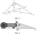
- the field of view angle (field of view area) has a first side AD far away from the body front end and a second side AC close to the body front end that are projected onto the horizontal ground in the traveling direction of the body.
- the second side AC is parallel to a tangent (a straight line passing through OK) of the body front end 106.
- the field of view area has a first side AD far away from the body front end and a second side AC close to the body front end that are projected onto grass in the traveling direction of the body.
- the second side AC partially overlaps a tangent (as shown by the dash line in FIG. 4 or a straight line passing through OK in FIG. 10 ) of the body front end 106.
- the image acquisition apparatus has internal parameters.
- the internal parameters include a vertical field of view angle.
- a field of view area of a projection of the field of view coverage area of the image acquisition apparatus onto a plane with the preset height has a first side AD far away from the body front end and a second side AC close to the body front end that are projected onto grass in the traveling direction of the body.
- the first side AD and the second side AC form the vertical field of view angle a2 (or 4CAD).
- the second side AC partially overlaps the tangent of the body front end.
- the second side on a side of the field of view close to the body in the traveling direction of the body is completely perpendicular to or flush with the front end of the machine, or a perpendicular from the central point of the image acquisition apparatus to the second field of view boundary is tangent to the body front end or at least partially overlaps the body front end, to eliminate blind spots of the image acquisition apparatus in both the traveling direction and a height direction perpendicular to the working area.
- the preset blind spot threshold is 150 mm.
- the distance between the second field of view boundary and the body front end is related to the installation parameters of the image acquisition apparatus, the internal parameters of the image acquisition apparatus, and the preset height.
- the distance between the second field of view boundary and the body front end is determined based on the installation parameters of the image acquisition apparatus, the internal parameters of the image acquisition apparatus, and the preset height h3.
- the installation parameters at least include an installation height h1, an installation distance x0, and an installation angle, where the installation height h1 is a height of the image acquisition apparatus from a horizontal ground, and the installation distance x0 is a horizontal distance of the image acquisition apparatus from the body front end.
- the installation angle includes a lens rotation angle a3, and the lens rotation angle a3 is an included angle between a lens central axis of the image acquisition apparatus and a vertical direction.
- the installation angle may further include a horizontal installation angle a1, and the horizontal installation angle a1 is an included angle between a perpendicular of the lens central axis of the image acquisition apparatus and a horizontal line.
- the installation distance x0 can be adjusted by adjusting the horizontal installation angle a1.
- the internal parameters include a vertical field of view angle a2.
- the vertical field of view angle a2 is configured for determining a maximum detection distance of the image acquisition apparatus in the traveling direction of the body.
- the preset height may be determined based on a grass height or an obstacle height in the working area.
- the value range of the preset height h3 is 0 mm ⁇ h3 ⁇ 150 mm.
- the value range of the installation height h1 is 150 mm ⁇ h1 ⁇ 500 mm.
- a value range of the vertical field of view angle a2 of the image acquisition apparatus is 45° ⁇ a2 ⁇ 90°.
- the range of the lens rotation angle a3 is 0 ⁇ a3 ⁇ 75°.
- the value range of the installation distance X0 of the image acquisition apparatus is 0 ⁇ x0 ⁇ 220 mm.
- a value range of the installation angle a1 is 0 ⁇ a1 ⁇ 90°.
- the parameters are limited within corresponding small ranges, so that regardless of how to select the parameters within the corresponding small ranges, it is met that the first field of view boundary is greater than the braking distance and the image recognition distance (i.e., the first distance can adapt to any scenario in which the response distance is within 325 mm), and it can also be met that the detection blind spot is not excessively large (the blind spot is controlled from exceeding 150 mm), thereby greatly improving the safety and passability of the autonomous lawn mower, and reducing trouble for users.
- the internal parameters further include a horizontal field of view angle a4, where the horizontal field of view angle a4 is configured for determining the maximum detection distance of the image acquisition apparatus in the body width direction.
- the value range of the horizontal field of view angle a4 of the image acquisition apparatus is 60° to 160°.
- a ratio of the horizontal field of view angle a4 to the vertical field of view angle a2 of the image acquisition apparatus is 4:3 or 16:9.
- a camera with a lens aspect ratio of 4:3 or 16:9 may be chosen for the image acquisition apparatus.
- the horizontal field of view angle a4 is equal to 130°
- the vertical field of view angle a2 is equal to 73°.
- a time taken for a target object in a field of view range of the image acquisition apparatus to appear and leave is not less than an image recognition time t1 of the autonomous lawn mower.
- the time taken for the target object to appear and leave is determined by using the following method: determining the time based on a transverse effective distance in the field of view range of the image acquisition apparatus and a walking speed v of the autonomous lawn mower.
- the transverse effective distance is a distance of subtracting a blocking distance of a blocking object from the detection distance of the image acquisition apparatus.
- the blocking object includes the autonomous lawn mower and/or a target object.
- the target object includes a boundary and an obstacle.
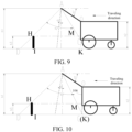
- transverse effective distance in the field of view range of the image acquisition apparatus is briefly described below with reference to FIG. 8 to FIG. 10 .
- the detection distance of the image acquisition apparatus is DC
- the blocking distance of the blocking object includes a first distance DI blocked by a grass height HI and a second distance blocked by the autonomous lawn mower. Therefore, it may be obtained that the transverse effective distance in the field of view range of the image acquisition apparatus is IK.
- the detection distance of the image acquisition apparatus is DK.
- DK may also be understood as a distance of subtracting the second distance blocked by the autonomous lawn mower from the detection distance.
- the blocking distance of the blocking object only includes the first distance DI blocked by the grass height HI. Therefore, it may be obtained that the transverse effective distance in the field of view range of the image acquisition apparatus is IK.
- the detection distance of the image acquisition image acquisition apparatus is DC
- the blocking distance of the blocking object only includes a first distance DI blocked by a grass height HI. Therefore, it may be obtained that the transverse effective distance in the field of view range of the image acquisition apparatus is IK.
- the field of view angle includes a third field of view boundary located on a left side of the traveling direction and a fourth field of view boundary located on a right side of the traveling direction in a direction perpendicular to the traveling direction of the body.
- a distance between the third field of view boundary and the fourth field of view boundary is 1.2 to 3 times a body width of the autonomous lawn mower. In this way, in one aspect, a blind spot in the body width direction can be reduced or even eliminated, and in another aspect, the problem that machine recognition is affected due to excessively low image resolution can be avoided.
- a value range of the body width is 400 mm to 550 mm.
- the distance between the third field of view boundary and the fourth field of view boundary is determined based on the installation parameters, internal parameters of the image acquisition apparatus, and the preset height h3; the installation parameters at least include an installation height h1; and the internal parameters of the image acquisition apparatus include a horizontal field of view angle a4, where the horizontal field of view angle a4 is configured for determining a detection distance of the image acquisition apparatus in a body width direction.
- the value range of the preset height h3 is 0 mm ⁇ h3 ⁇ 150 mm
- the value range of the installation height h1 is 150 mm ⁇ h1 ⁇ 500 mm.
- the value range of the horizontal field of view angle a4 of the image acquisition apparatus is 60° ⁇ a4 ⁇ 160°.
- the internal parameters of the image acquisition apparatus further include a vertical field of view angle a2, and a value range of the vertical field of view angle a2 of the image acquisition apparatus is 48° ⁇ a2 ⁇ 90°.
- a ratio of the horizontal field of view angle a4 to the vertical field of view angle a2 is 4:3 or 16:9.
- the horizontal field of view angle a4 is equal to 130°
- the vertical field of view angle a2 is equal to 73°.
- the field of view area of the projection of the field of view coverage area of the image acquisition apparatus onto the plane with the preset height includes a third field of view boundary located on a left side of the traveling direction and a fourth field of view boundary located on a right side of the traveling direction in a direction perpendicular to the traveling direction of the body, where a distance between the third field of view boundary or the fourth field of view boundary and a corresponding lateral side of the body is not less than a steering radius of the autonomous lawn mower.
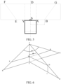
- the field of view coverage area of the image acquisition apparatus at least includes a tapered area defined by a point A, a point B, a point C, a point D, and a point E.
- the point A represents the central point of the image acquisition apparatus.
- the point B and the point E respectively represent farthest field of view positions in the body width direction.
- the point C and the point D respectively represent farthest field of view boundary points in a body length direction or the traveling direction.
- the tapered area may be, for example, a pyramidal area, or may be a tapered area. In an embodiment, the tapered area may be, for example, a four-sided pyramid.
- the image acquisition apparatus has internal parameters.
- the internal parameters include a horizontal field of view angle and a vertical field of view angle.
- a field of view area of a projection of the field of view coverage area of the image acquisition apparatus onto the horizontal ground is an area defined by the point B, the point C, the point D, and the point E.
- the field of view area of the projection of the field of view coverage area onto the horizontal ground has two sides that are respectively far away from the body front end and close to the body front end and are projected onto the horizontal ground in the traveling direction of the body, and are respectively represented by AD and AC.
- An included angle 4CAD between AD and AC is the vertical field of view angle of the image acquisition apparatus.
- the side AC that is projected onto the horizontal ground and is close to the body front end in the traveling direction of the body of the field of view area of the projection of the image acquisition apparatus onto the horizontal ground may fall in rear of the body front end (as shown in FIG. 9 ), may be blocked by the body, or may fall in front of the body front end (as shown in FIG. 7 ), resulting in a field of view blind spot at the body front end.
- a distance between the side AC and the body front end is equal to 0, as shown in FIG. 10 .
- a field of view blind spot may still exist in a body height direction of the body front end.
- the preset height is greater than 0, a timely response cannot be made to an object that suddenly appears in the direction of a height 2 near the body front end, which tends to cause a danger.
- the installation angle a1 is adjusted to make AC at least partially overlap the body front end and at least partially overlap a tangent of the body front end.
- the rotation angle a3 may be first determined from the perspective of protecting the image acquisition apparatus (for example, against rain or snow), and then the installation angle a1 is adjusted to make AC at least partially overlap the body front end and at least partially overlap a tangent of the body front end.
- AC at least partially overlaps the tangent of the body front end, to eliminate a blind spot at the body front end.
- AC is tangent to the body front end.
- the field of view area of the projection of the field of view coverage area onto the horizontal ground includes a field of view boundary BE close to the body front end and a field of view boundary FG far away from the body front end in the traveling direction of the body.
- the field of view boundary BE is a line segment passing through the point C
- the field of view boundary FG is a line segment passing through the point D.
- the field of view area of the projection of the field of view coverage area onto the horizontal ground is a trapezoidal area defined by the point B, the point E, a point F, and a point G.
- FIG. 3 and FIG. 5 schematically show the body width (represented by XY).
- HI represents the preset height h3.
- a field of view area of the projection of the field of view coverage area onto the plane with the preset height h3 greater than 0 may be an area defined by a point P, a point M, a point H, and a point Q.
- PM is parallel to BC;
- MQ is parallel to CE;
- HM is parallel to CD; and
- MC HI.
- the field of view area of the projection of the field of view coverage area onto the horizontal ground may be the area defined by the point B, the point C, the point D, and the point E.
- the field of view area of the projection of the field of view coverage area onto the plane with the preset height h3 greater than 0 includes a first field of view boundary far away from the body front end and a second field of view boundary PQ close to the body front end in the traveling direction of the body.
- the first field of view boundary is not shown in FIG. 6 , it may be understood that the first field of view boundary is located in a plane (a plane in which HM is located in FIG. 7 ) at a height from the horizontal ground being h3 greater than 0.
- the first field of view boundary is a line segment passing through the point H, and the first field of view boundary is parallel to the field of view boundary FG of the projection onto the horizontal ground.
- the second field of view boundary PQ is a line segment passing through the point M, and the second field of view boundary PQ is parallel to the field of view boundary BE of the projection onto the horizontal ground.
- the field of view area of the projection of the field of view coverage area onto the plane with the preset height h3 greater than 0 is a trapezoidal area defined by four vertices of the first field of view boundary and the second field of view boundary PQ that pass through the point H and is parallel to the field of view boundary FG of the projection onto the horizontal ground.
- the installation parameter of the image acquisition apparatus is configured as a first parameter, and the image acquisition apparatus is further kept from being blocked by other members of the autonomous lawn mower, i.e., the other members are kept from falling within the detection range of the image acquisition apparatus.
- Constraint condition 4 The time (the image recognition time) required for the machine to recognize an image should be less than or equal to a time from an object appearing at a far-end field of view boundary of the field of view area of the projection of the field of view coverage area of the image acquisition apparatus onto the horizontal ground or the plane with the preset height in the traveling direction of the body (starting to capture an image of the object) to the object leaving the near-end field of view boundary of the field of view area of the projection of the field of view coverage area of the image acquisition apparatus onto the horizontal ground or the plane with the preset height in the traveling direction of the body (completing the capturing of the image of the object).
- Constraint condition 5 A field of view range covered by the horizontal field of view angle of the image acquisition apparatus should meet that no collision occurs with an obstacle during steering.
- a height of the image acquisition apparatus from the ground is h1 (mm); a height of the autonomous lawn mower from the ground is h2 (mm); the preset height (for example, the grass height or the obstacle height) is h3 (mm); the traveling speed of the autonomous lawn mower is v (mm/s); the image processing time of the image acquisition apparatus is t1 (s); the braking time (a time from normal driving to complete stop) of the machine is t2 (s); the installation angle of the image acquisition apparatus is a1 (°); the vertical field of view angle of the image acquisition apparatus is a2 (°); the lens rotation angle of the image acquisition apparatus is a3 (°); a length of a projection CD of a boundary of the vertical field of view angle of the image acquisition apparatus onto the horizontal ground is x1 (mm); a length of a distance DK between a projection of the far-end field of view boundary of the image acquisition apparatus in the traveling direction of the body onto the horizontal ground and the body front end is x2 (mm); a
- a value range of the cantilever length L (OA) is 0 ⁇ L.
- a value range of k is 0 ⁇ k ⁇ b, where b represents the body width. It may be understood that the value range of k represents that the image acquisition apparatus may be located at the body front end and disposed toward the rear.
- x0 Lcos ⁇ 1 - k, where x0 is the installation distance of the image acquisition apparatus, representing a horizontal distance between the image acquisition apparatus and the body front end 106.
- An installation constraint in the vertical field of view angle at least includes one of the following: Constraint A: A distance between a field of view boundary of the projection onto the horizontal ground and the body front end is greater than or equal to the response distance of the autonomous lawn mower.
- the response distance is related to the braking distance and the image recognition distance
- x 2 h 1 tan a 2 / 2 + a 3 + Lcosa 1 ⁇ k ⁇ t 1 v + x 5 ,
- a range of the installation distance x0 of the image acquisition apparatus is 0 mm to 220 mm.
- A2 When a boundary line or an obstacle appears in front of the autonomous lawn mower, in any scenario in which the autonomous lawn mower avoids crossing a boundary in a steering manner or steers to walk along an edge or avoids an obstacle, the steering distance may be adopted.
- a steering radius r is used in place of x5 in the foregoing formula to obtain an installation constraint in the vertical field of view angle in the steering scenario. For brevity, this is no longer excessively described in this embodiment.
- Constraint C A time taken for a target object on a horizontal ground to appear and leave is not less than the image recognition time t1 of the autonomous lawn mower.
- the target object may be, for example, a target object, especially a branch, a rock, or another still obstacle, or may be a boundary line or another object.
- a range of the body height 2 is 190 mm to 220 mm.
- x1 x2.
- x 3 h 1 ⁇ h 3 tan a 2 / 2 + a 3 + tan a 2 / 2 ⁇ a 3
- x 4 h 1 ⁇ h 3 tan a 2 / 2 + a 3 + Lcosa 1 ⁇ k
- x0 Lcosa 1 - k
- An installation constraint in the vertical field of view angle at least includes one of the following: Constraint Q: A distance between the field of view boundary (i.e., the first field of view boundary) of the projection onto the plane with the preset height and the body front end is greater than or equal to the response distance of the autonomous lawn mower: Q1: When a boundary line or an obstacle appears or is detected in front of the autonomous lawn mower, in a scenario in which the autonomous lawn mower avoids crossing a boundary or steers to walk along an edge in a steering manner:
- the braking distance x5 is approximately equal to vt2.
- the steering distance may be adopted.
- a steering radius r is used in place of x5 in the foregoing formula to obtain an installation constraint in the vertical field of view angle in the steering scenario. For brevity, this is no longer excessively described in this embodiment.
- Constraint P The image recognition time t1 of the autonomous lawn mower is less than or equal to a time taken for a target object on a plane with the preset height to appear and leave.
- a time from the target object appearing at the first field of view boundary (the camera is ready to capture an image of the object) to the target object leaving the second field of view boundary (the camera completes the capturing of the image of the object) should be greater than or equal to the time required for the machine to recognize an image.
- the target object may be, for example, a target object, especially a branch, a rock, or another still obstacle, or may be a boundary line or another object.
- the image acquisition apparatus is installed on the body and is not rotatable around an optical axis of the lens thereof, the factors to be taken into consideration in the installation of the image acquisition apparatus are briefly described below with reference to FIG. 7 to FIG. 11 .
- the horizontal distance between the image acquisition apparatus and the body front end is x0 (mm); the preset height or the grass height or the obstacle height is h3 (mm); the traveling speed of the autonomous lawn mower is v (mm/s); the image processing time of the image acquisition apparatus is t1 (s); the braking time (a time from normal driving to complete stop) of the machine is t2 (s); the installation angle of the image acquisition apparatus is a1 (°); the vertical field of view angle of the image acquisition apparatus is a2 (°); a length of a projection CD of a boundary of the vertical field of view angle of the image acquisition apparatus onto the horizontal ground is x1 (mm); a length of a distance DK between a projection of the far-end field of view boundary of the image acquisition apparatus in the traveling direction of the body onto the horizontal ground and the body front end is x2 (mm); a length of a horizontal projection HM of the grass height (or obstacle) within the field of view angle of the image acquisition apparatus is x3 (mm); a
- x 1 h 1 tan a 2 / 2 + a 3 + tan a 2 / 2 ⁇ a 3
- x 2 h 1 tan a 2 / 2 + a 3 + x 0 .
- Constraint 1 A distance between a field of view boundary of the projection onto the horizontal ground and the body front end is greater than or equal to the response distance of the autonomous lawn mower.
- x 2 h 1 tan a 2 / 2 + a 3 + x 0 ⁇ x 5 , because the braking distance x 5 is related to the braking time t2 and the traveling speed v, in an embodiment, the braking distance x5 is approximately equal to vt2.
- Constraint 2 A time taken for a target object on a horizontal ground to appear and leave is not less than the image recognition time t1 of the autonomous lawn mower.
- the target object may be, for example, a target object, especially a branch, a rock, or another still obstacle, or may be a boundary line or another object.
- Constraint 3 The distance between the second field of view boundary and the body front end is less than or equal to a preset blind spot distance, and the body of the machine does not appear in the field of view.
- the field of view blind spot should not be excessively large.
- the preset height is 0, the preset blind spot distance is 150 mm.
- a constraint that should be met is expressed by using a formula as follows: 0 ⁇ h 2 ⁇ h 1 tan a 2 / 2 ⁇ a 1 ⁇ 150 .
- condition of the boundary is: 0 ° ⁇ a 3 ⁇ 90 ° , 0 ° ⁇ a 1 ⁇ 180 ° , and 0 ⁇ h 2 ⁇ h 1 .
- a constraint that the installation height of the image acquisition apparatus should meet is: 200 mm ⁇ h 1 ⁇ 500 mm .
- x 3 h 1 ⁇ h 3 tan a 2 / 2 + a 3 + tan a 2 / 2 ⁇ a 3
- x 4 h 1 ⁇ h 3 tan a 2 / 2 + a 3 + x 0 .
- the machine needs to have a compact structure and a simple and aesthetic appearance, and the safety performance (blind spot) of the machine needs to be ensured.
- the appropriateness of selecting field of view angles and installation angles of the image acquisition apparatus is verified. For example, it is verified in the length direction that there is at least a distance of 2 seconds between the body and the farthest end of the field of view, to ensure safety and also avoid an excessively large blind spot. It is verified in the width direction that the body width needs to be completely covered, and a specific margin (0.5 times of the width of the machine) is reserved to eliminate a blind spot. However, the margin cannot be excessively large, or otherwise the effective image resolution is excessively low, which affects recognition.
- a further determined range is as follows: 200 mm ⁇ h1 ⁇ 423 mm , 0 ° ⁇ a1 ⁇ 107 ° , 30 ° ⁇ a3 ⁇ 68 ° , 50 ° ⁇ a2 ⁇ 90 ° , and 0 ⁇ x0 ⁇ 83 mm .
- the machine when the machine runs to a boundary of a lawn, if an obstacle (for example, a wall, or a fence) taller than the lawn is present at the boundary of the lawn, the obstacle should be captured in the field of view of the camera, and the field of view should not be completely covered by the vegetation.
- the machine For a position at a distance of b/2 from the center of the field of view of the camera in the width direction (b is the body width), if a space taller than the vegetation cannot be detected in the field of view of the camera and it is directly considered that the machine is safe, the machine may continue to move toward the obstacle, and as a result the machine collides with the obstacle.
- a constraint condition 6 may be determined according to an extreme case.
- an obstacle is tightly joined to a lateral side of the machine, i.e., at the position at a distance of b/2 from the center of the field of view of the camera in the width direction, an obstacle taller than the vegetation is right detected in the field of view of the camera.
- a height detectable in the field of view of the camera should be greater than or equal to a height h3 of the vegetation.
- the lateral constraint conditions are described below with reference to FIG. 6 , FIG. 7 , FIG. 15, and FIG. 16 .
- the field of view of the camera is an irregular ellipsoid. To simplify calculation, the shape can be approximately considered as a triangle.
- AS h 1 cosa 3
- FIG. 15 is a schematic diagram of a position relationship between a projection of the field of view of the camera onto the horizontal plane and a projection of the body on the horizontal plane.
- UV is parallel to DC
- UV is colinear with the lateral side of the body of the lawn mower
- a distance between UV and DC is a half of the width (b/2) of the lawn mower.
- FIG. 16 is a schematic diagram of the field of view of the camera in the direction of BC. Due to the blockage of vegetation, an obstacle cannot be detected in the field of view of the camera corresponding to the dash line in the figure. Therefore, a height of the field of view at Z' should be greater than or equal to the height of the vegetation before an obstacle near Z' can be detected, thereby reducing a probability that the machine collides with an obstacle.
- a constraint condition of keeping the machine from colliding with an obstacle includes: at the position at the distance of b/2 from the center of the field of view of the camera in the width direction, the height detectable in the field of view of the camera is h4 ⁇ the height h3 of the vegetation.
- h 4 h 1 h 1 cosa 3 tan a 4 2 ⁇ b 2 h 1 cosa 3 tan a 4 2
- h 4 2 h 1 tan a 4 2 ⁇ bcosa 3 2 tan a 4 2
- h4 ⁇ h3 is: 2 h 1 tan a 4 2 ⁇ bcosa 3 2 tan a 4 2 ⁇ h3 .
- a further determined range is as follows: the value range of the installation height h1 is 218 mm ⁇ h1 ⁇ 434 mm; the value range of the installation distance x0 is 0 ⁇ x0 ⁇ 83 mm; the value range of the horizontal installation angle a1 is 0° ⁇ a1 ⁇ 86°; the value range of the vertical field of view angle a2 is 45° ⁇ a2 ⁇ 90°; and the value range of the lens rotation angle a3 is 52° ⁇ a3 ⁇ 68°.
- the distance between the first field of view boundary and the body front end is 1600 mm.
- x 1 h 1 tan a 2 / 2 + a 1 + tan a 2 / 2 ⁇ a 1
- x 2 h 1 tan a 2 / 2 + a 1 + x 0
- x 2 h 1 tan a 2 / 2 + a 3 + x 0 ⁇ x 5
- x 2 / v h 1 tan a 2 / 2 + a 1 + x 0 / v ⁇ t 2
- x 1 / v h 1 tan a 2 / 2 + a 1 + x 0 / v ⁇ t 2
- x 1 / v h 1 tan a 2 / 2 + a 1 + tan a 2 / 2 ⁇ a 1 / v ⁇ t 1
- the boundary condition that should be met is: a 1 + a 2 / 2 ⁇ 90 ° .
- the image acquisition apparatus should obtain an as wide as possible field of view range in the use process, to improve the safety of the machine, as shown in FIG. 14 , it is a critical state when a field of view centerline of the field of view of the image acquisition apparatus is perpendicular to the horizontal plane.
- x3 h 1 ⁇ h 3 tan a 2 / 2 + a 1 + tan a 2 / 2 ⁇ a 1
- x4 h 1 ⁇ h 3 tan a 2 / 2 + a 1 + x 0 .
- the machine needs to have a compact structure and a simple and aesthetic appearance, and the safety performance (blind spot) of the machine needs to be ensured.
- the appropriateness of selecting field of view angles and installation angles of the image acquisition apparatus is verified. For example, it is verified in the length direction that there is at least a distance of 2 seconds between the body and the farthest end of the field of view, to ensure safety and also avoid an excessively large blind spot. It is verified in the width direction that the body width needs to be completely covered, and a specific margin (0.5 times of the width of the machine) is reserved to eliminate a blind spot. However, the margin cannot be excessively large, or otherwise the effective image resolution is excessively low, which affects recognition.
- a further determined range is as follows: 200 ⁇ h 1 ⁇ 400 , 30 ° ⁇ a 1 ⁇ 45 ° , 30 ° ⁇ a 3 ⁇ 45 ° , 60 ° ⁇ a 2 ⁇ 80 ° , and 0 ⁇ x 0 ⁇ 40 mm .
- the distance between the first field of view boundary and the body front end is 808 mm.
- the field of view range covered by the horizontal field of view angle of the image acquisition apparatus should meet that no collision occurs with an obstacle during steering.
- the constraint condition in the body width direction includes: Constraint B: The horizontal field of view angle of the image acquisition apparatus should meet that a boundary line or an obstacle is not touched during steering or a distance to a boundary line or an obstacle in a steering process is within an error range.
- the field of view area of the projection of the field of view coverage area of the image acquisition apparatus onto the plane with the preset height includes a third field of view boundary located on a left side of the traveling direction and a fourth field of view boundary located on a right side of the traveling direction in a direction perpendicular to the traveling direction of the body.
- a distance between the third field of view boundary or the fourth field of view boundary and a corresponding lateral side of the body is not less than a steering radius of the autonomous lawn mower.
- the installation height of the image acquisition apparatus is h1 (unit: mm, millimeter), and the horizontal field of view angle of the image acquisition apparatus is a4 (unit: degree, °).
- a distance between the projections of the centerline of the image acquisition apparatus and the boundary of the horizontal field of view angle onto the horizontal ground is x6 (unit: mm, millimeter); the steering radius of the machine is r (unit: mm, millimeter); and the width XY of the machine is b (unit: mm, millimeter).
- the constraint in the horizontal field of view angle is: h 1 ⁇ h 3 tan a 4 / 2 ⁇ r ⁇ b / 2 .
- the field of view area of the projection of the field of view coverage area of the image acquisition apparatus onto the horizontal ground with the preset height h3 being 0 includes a field of view boundary located on a left side of the traveling direction and a field of view boundary located on a right side of the traveling direction in a direction perpendicular to the traveling direction of the body.
- a distance between the two field of view boundaries is 1.8 times to 2.2 times the body width of the autonomous lawn mower.
- the field of view area of the projection of the field of view coverage area of the image acquisition apparatus onto the plane with the preset height (for example, grass height) h3 being greater than 0, for example, h3 150 mm, includes a third field of view boundary located on a left side of the traveling direction and a fourth field of view boundary located on a right side of the traveling direction in a direction perpendicular to the traveling direction of the body, where a distance between the third field of view boundary and the fourth field of view boundary is 1.6 times to twice the body width of the autonomous lawn mower.
- the image acquisition apparatus may be, for example, a depth camera, installed on the body, and configured to acquire an image in the traveling direction of the machine.
- the depth camera is further configured to recognize an obstacle in the image, to be specific, when an obstacle appears in the image, determine a type of the obstacle.
- the obstacle may be a still object or may be a moving object.
- the type of the obstacle includes, but is not limited to, a rock, a tree, or another lifeless object, and an animal, person, or another living object.
- the depth camera depends on visual artificial intelligence (AI) to implement the recognition of an obstacle.
- AI visual artificial intelligence
- the depth camera may recognize an obstacle based on a deep learning algorithm with supervised learning, for example, recognize the type of the obstacle based on a pre-trained convolutional neural network model. It may be understood that the depth camera may implement the recognition of an obstacle based on another machine learning or deep learning algorithm. This is not specifically limited in this embodiment.
- the depth camera may be a monocular camera, a binocular camera, or a trinocular stereo camera.
- the depth camera is a trinocular stereo camera to implement three-dimensional recognition of an obstacle.
- the depth camera is installed at a top front end or a front top end of the body of the machine.
- the depth camera is installed at an externally disposed anti-collision housing (for example, a cantilever) in an embedded manner, to avoid damage from collision.
- an externally disposed anti-collision housing for example, a cantilever
- an installation height of the depth camera is 220 mm.
- the depth camera is installed at a top of the body of the machine, and is disposed facing downward.
- a horizontal installation angle is set to 38°
- a lens rotation angle is set to 53°
- a vertical field of view angle of the depth camera is set to 73°
- a horizontal field of view angle is set to 130°.
- an installation height of the depth camera is 220 mm.
- the depth camera is installed at a top of the body of the machine, and is disposed facing downward.
- a lens rotation angle and a horizontal installation angle are equal, and are both 38°, a vertical field of view angle of the depth camera is set to 73°, and a horizontal field of view angle is set to 130°.
Landscapes
- Engineering & Computer Science (AREA)
- Physics & Mathematics (AREA)
- General Physics & Mathematics (AREA)
- Environmental Sciences (AREA)
- Life Sciences & Earth Sciences (AREA)
- Multimedia (AREA)
- Radar, Positioning & Navigation (AREA)
- Remote Sensing (AREA)
- Aviation & Aerospace Engineering (AREA)
- Automation & Control Theory (AREA)
- Theoretical Computer Science (AREA)
- Signal Processing (AREA)
- Electromagnetism (AREA)
- Computer Networks & Wireless Communication (AREA)
- Control Of Position, Course, Altitude, Or Attitude Of Moving Bodies (AREA)
- Guiding Agricultural Machines (AREA)
Applications Claiming Priority (3)
| Application Number | Priority Date | Filing Date | Title |
|---|---|---|---|
| CN202210390617 | 2022-04-14 | ||
| CN202220882548 | 2022-04-14 | ||
| PCT/CN2023/087522 WO2023198029A1 (fr) | 2022-04-14 | 2023-04-11 | Tondeuse automatique |
Publications (2)
| Publication Number | Publication Date |
|---|---|
| EP4508968A1 true EP4508968A1 (fr) | 2025-02-19 |
| EP4508968A4 EP4508968A4 (fr) | 2026-03-11 |
Family
ID=88328924
Family Applications (1)
| Application Number | Title | Priority Date | Filing Date |
|---|---|---|---|
| EP23787673.5A Pending EP4508968A4 (fr) | 2022-04-14 | 2023-04-11 | Tondeuse automatique |
Country Status (4)
| Country | Link |
|---|---|
| US (1) | US20250036139A1 (fr) |
| EP (1) | EP4508968A4 (fr) |
| CN (1) | CN116998301A (fr) |
| WO (1) | WO2023198029A1 (fr) |
Family Cites Families (11)
| Publication number | Priority date | Publication date | Assignee | Title |
|---|---|---|---|---|
| JPH03276313A (ja) * | 1990-03-27 | 1991-12-06 | Mazda Motor Corp | 移動車の環境認識装置 |
| JPH08329398A (ja) * | 1995-05-30 | 1996-12-13 | Nissan Motor Co Ltd | 走行路検出装置 |
| CN107291071A (zh) * | 2016-03-30 | 2017-10-24 | 苏州宝时得电动工具有限公司 | 自动工作系统、自动行走设备及其转向方法 |
| CN107006229A (zh) * | 2017-03-30 | 2017-08-04 | 江苏科技大学 | 一种坐骑式割草机翻滚保护装置及其保护方法 |
| JP7000232B2 (ja) * | 2018-04-02 | 2022-02-04 | 株式会社東芝 | 前方監視装置、支障物衝突回避装置及び列車制御装置 |
| CN110612806B (zh) * | 2018-06-19 | 2021-04-20 | 灵动科技(北京)有限公司 | 一种智能割草机 |
| CN110612492A (zh) * | 2018-06-20 | 2019-12-24 | 灵动科技(北京)有限公司 | 一种自驱动无人驾驶割草机 |
| CN109063575B (zh) * | 2018-07-05 | 2022-12-23 | 中国计量大学 | 一种基于单目视觉的智能割草机自主有序割草方法 |
| CN109343079A (zh) * | 2018-10-30 | 2019-02-15 | 合肥泰禾光电科技股份有限公司 | 一种测距避障方法及避障装置 |
| EP3874924B1 (fr) * | 2018-11-20 | 2023-08-09 | Honda Motor Co., Ltd. | Machine de travail autonome, procédé de commande de machine de travail autonome, et programme |
| CN113156929B (zh) * | 2020-01-06 | 2024-02-23 | 苏州宝时得电动工具有限公司 | 自移动设备 |
-
2023
- 2023-04-11 EP EP23787673.5A patent/EP4508968A4/fr active Pending
- 2023-04-11 WO PCT/CN2023/087522 patent/WO2023198029A1/fr not_active Ceased
- 2023-04-11 CN CN202310379028.XA patent/CN116998301A/zh active Pending
-
2024
- 2024-10-14 US US18/914,960 patent/US20250036139A1/en active Pending
Also Published As
| Publication number | Publication date |
|---|---|
| US20250036139A1 (en) | 2025-01-30 |
| EP4508968A4 (fr) | 2026-03-11 |
| WO2023198029A1 (fr) | 2023-10-19 |
| CN116998301A (zh) | 2023-11-07 |
Similar Documents
| Publication | Publication Date | Title |
|---|---|---|
| US11188087B2 (en) | Autonomous working system, autonomous vehicle and steering method thereof | |
| EP3798781B1 (fr) | Tondeuse automatique et procédé de guidage | |
| US20220187829A1 (en) | An autonomous working system, an autonomous vehicle and a turning method thereof | |
| CN211015146U (zh) | 自主机器人 | |
| EP2939513B1 (fr) | Robot pour tondre le gazon et son procédé de commande | |
| WO2021139683A1 (fr) | Dispositif automoteur | |
| KR20190123673A (ko) | 이동 로봇 및 그 제어방법 | |
| US11582903B1 (en) | Vision based guidance system and method for lawn mowing devices | |
| CN113156929B (zh) | 自移动设备 | |
| WO2021238001A1 (fr) | Procédé et système de commande de déplacement de robot, robot et support de stockage lisible | |
| WO2021114988A1 (fr) | Robot autonome et son procédé de commande, et support de stockage informatique | |
| US12298784B1 (en) | Visual identifiers for docking and zoning an autonomous mower | |
| US20240276909A1 (en) | Automatic lawn mower | |
| CN105911981A (zh) | 自动工作系统、自动行走设备及其转向方法 | |
| Gao et al. | Design and implementation of an autonomous driving delivery robot | |
| EP4508968A1 (fr) | Tondeuse automatique | |
| CN119087992A (zh) | 自移动设备控制方法及自移动设备 | |
| CN222838368U (zh) | 自主作业系统的标记设备 | |
| CN115971191B (zh) | 一种光伏清洗机器人的运行控制方法及光伏清洗机器人 | |
| US20240119842A1 (en) | Methods and Systems for Coupling Vehicles | |
| CN113534800B (zh) | 一种循迹控制方法、自动行走设备及可读存储介质 | |
| WO2026041148A1 (fr) | Dispositif mobile autonome et procédé de commande associé | |
| CN121143342A (zh) | 避障方法、机器人及计算机可读存储介质 | |
| CN119690060A (zh) | 智能割草机控制方法、装置、存储介质及智能割草机 | |
| CN121002458A (zh) | 一种自主机器人、路径规划方法 |
Legal Events
| Date | Code | Title | Description |
|---|---|---|---|
| STAA | Information on the status of an ep patent application or granted ep patent |
Free format text: STATUS: THE INTERNATIONAL PUBLICATION HAS BEEN MADE |
|
| PUAI | Public reference made under article 153(3) epc to a published international application that has entered the european phase |
Free format text: ORIGINAL CODE: 0009012 |
|
| STAA | Information on the status of an ep patent application or granted ep patent |
Free format text: STATUS: REQUEST FOR EXAMINATION WAS MADE |
|
| 17P | Request for examination filed |
Effective date: 20241112 |
|
| AK | Designated contracting states |
Kind code of ref document: A1 Designated state(s): AL AT BE BG CH CY CZ DE DK EE ES FI FR GB GR HR HU IE IS IT LI LT LU LV MC ME MK MT NL NO PL PT RO RS SE SI SK SM TR |
|
| DAV | Request for validation of the european patent (deleted) | ||
| DAX | Request for extension of the european patent (deleted) | ||
| A4 | Supplementary search report drawn up and despatched |
Effective date: 20260211 |
|
| RIC1 | Information provided on ipc code assigned before grant |
Ipc: A01D 34/00 20060101AFI20260205BHEP Ipc: G06V 20/10 20220101ALI20260205BHEP Ipc: A01D 75/18 20060101ALI20260205BHEP Ipc: G01S 17/931 20200101ALI20260205BHEP Ipc: G05D 1/243 20240101ALI20260205BHEP Ipc: G05D 1/622 20240101ALI20260205BHEP Ipc: H04N 23/695 20230101ALI20260205BHEP Ipc: G06V 20/56 20220101ALI20260205BHEP |
|
| P01 | Opt-out of the competence of the unified patent court (upc) registered |
Free format text: CASE NUMBER: UPC_APP_0008572_4508968/2026 Effective date: 20260303 |