EP4509016A1 - Châssis de chaise multifonction rotatif à 360 degrés et à retour automatique avec fonction d'oscillation - Google Patents
Châssis de chaise multifonction rotatif à 360 degrés et à retour automatique avec fonction d'oscillation Download PDFInfo
- Publication number
- EP4509016A1 EP4509016A1 EP24174935.7A EP24174935A EP4509016A1 EP 4509016 A1 EP4509016 A1 EP 4509016A1 EP 24174935 A EP24174935 A EP 24174935A EP 4509016 A1 EP4509016 A1 EP 4509016A1
- Authority
- EP
- European Patent Office
- Prior art keywords
- chair frame
- frame according
- multifunctional chair
- section
- bearing pin
- Prior art date
- Legal status (The legal status is an assumption and is not a legal conclusion. Google has not performed a legal analysis and makes no representation as to the accuracy of the status listed.)
- Pending
Links
Images
Classifications
-
- A—HUMAN NECESSITIES
- A47—FURNITURE; DOMESTIC ARTICLES OR APPLIANCES; COFFEE MILLS; SPICE MILLS; SUCTION CLEANERS IN GENERAL
- A47C—CHAIRS; SOFAS; BEDS
- A47C3/00—Chairs characterised by structural features; Chairs or stools with rotatable or vertically-adjustable seats
- A47C3/02—Rocking chairs
- A47C3/025—Rocking chairs with seat, or seat and back-rest unit, elastically mounted in a rigid frame
- A47C3/0252—Rocking chairs with seat, or seat and back-rest unit, elastically mounted in a rigid frame connected only by an elastic member positioned between seat and base frame
-
- A—HUMAN NECESSITIES
- A47—FURNITURE; DOMESTIC ARTICLES OR APPLIANCES; COFFEE MILLS; SPICE MILLS; SUCTION CLEANERS IN GENERAL
- A47C—CHAIRS; SOFAS; BEDS
- A47C3/00—Chairs characterised by structural features; Chairs or stools with rotatable or vertically-adjustable seats
- A47C3/18—Chairs or stools with rotatable seat
Definitions
- the present invention relates to a multifunctional chair frame with a stand device which has a rotating component which is connected to a seat holder via a bearing pin and can rotate about an axis of rotation running through the central longitudinal axis of the bearing pin.
- Such multifunctional chair frames are known from the state of the art in connection with swivel chairs, e.g. office chairs, kitchen chairs or the like. These state of the art chair frames either have a swivel function in connection with a tilting function, in which the seat unit can swivel backwards from a working position into a tilted rest position after a tilt lock is released. Such a chair frame then also has an automatic reset function. The seat unit is thus automatically moved back from the tilted rest position to the working position when the load is removed. In the working position and in the rest position, the respective seating positions are rigid, i.e. the respective seating position is determined locally within the material and assembly-related tolerances.
- the object of the present invention is therefore to develop a multifunctional chair frame of the type mentioned at the beginning in such a way that a determination of the sitting position can be optionally canceled.
- the seat holder comprises at least one freely swinging support element on which a seat can be attached.
- the present invention now has the advantage of being able to selectively bring about a sitting position that is indeterminate, at least with respect to a horizontal plane, from any specific sitting position.
- a further advantage of the present invention is that the at least one freely oscillating support element is connected to a rotary component that sits on the bearing journal. This makes it possible to perform the rotary function simultaneously with the oscillating function.
- the at least one freely oscillating support element engages with a lower support section on a front peripheral region of the rotary component and extends with an upper support section over a rear peripheral region of the rotary component.
- This design means that the oscillation capability of the at least one support element is essentially concentrated on an up and down movement. Fastening, for example, to the top of the rotary component allows more oscillation components in a forward and backward direction.
- the lower support section is essentially straight and the upper support section is essentially straight. This optimizes the alignment of the seat unit on the multifunctional chair frame.
- the upper support section effectively transfers forces via the lower support section to the rotating component.
- the chair frame can rotate 360 degrees, swing forward and backward, and automatically return.
- the seat mounted on the basis of this chair frame can be rotated or tilted at any time according to the human posture in a preferred embodiment, so that the seat allows flexible movement changes in different directions and continuous return forward and backward, thereby alleviating the user's physical fatigue, gradually relaxing the tense state of the body, and reducing the user's physical fatigue, gradually relaxes the tense state of the body and improves the comfort of the seat.
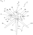
- the multifunctional chair frame S shown has, in the embodiment shown, a rotation function with 360-degree rotation, an automatic reset function and a swing function.
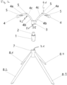
- the chair frame S comprises a support rod 1, at the free end or tip of which a bearing pin 2 is formed.
- the bearing pin 2 has a central longitudinal axis that coincides with a rotation axis D.
- the bearing pin 3 serves as a pivot bearing for a rotating component 3.
- the rotating component 3 has a corresponding receiving opening 3.2 on an underside 3.1.
- the rotating component 3 is mounted on the bearing pin 2 with the receiving opening 3.2, it is mounted so that it can rotate through 360° and can rotate in both directions around the bearing pin 2 and the rotation axis running through its central longitudinal axis.
- the bearing pin 2 also has an automatic reset mechanism However, in other embodiments, this reset mechanism may be omitted or may only be semi-automatic and/or manually operated.
- the rotating component 3 thus connects the first support element 4.1 and the second support element 4.2 of the seat holder 4, so that these two extend from it in a fork-like curved shape and each form a free end.
- the first support element 4.1 and the second support element 4.2 are rod-shaped/bar-shaped and mirror-symmetrical to one another and have a round or non-round, for example rectangular, square or polygonal cross-section.
- Each of the two support elements 4.1 and 4.2 is attached at one end to the front peripheral section 3.4.
- the attachment to the front peripheral section 3.4 can be fixed or detachable.
- a detachable connection between the respective one end and the front peripheral section 3.4 has the advantage of better disassembly and assembly for different purposes.
- the attachment of the first and second support elements 4.1 and 4.2 to the front peripheral area 3.4 of the rotating component 3 means that the oscillation behavior of the two support elements 4.1, 4.2 is essentially limited to swinging up and down.
- Each of the two support elements 4.1 and 4.2 has an upper support section 4a and a lower support section 4b, which are connected to one another via a connecting section 4c.
- the first and second support elements 4.1 and 4.2 are formed in one piece.
- the support elements 4.1 and 4.2 can also be formed in several parts and connected detachably or mechanically firmly (non-detachably).
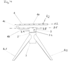
- the rotating component 3 lies in a first horizontal plane H1 and the upper support section 4a lies in at least a second horizontal plane H2, wherein the at least one second horizontal plane H2 lies above the first horizontal plane H1 and thus above the rotating component 3 during the intended use of the chair frame S.
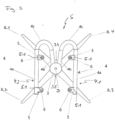
- the two upper support sections 4a lie essentially parallel to one another in the at least one second horizontal plane H2 and have the respective free end of the two support sections 4.1 and 4.2.
- the support rod 1 with the bearing pin 2 serves as the central pivot point of a seat and at the same time provides a central seat center of gravity.
- a seat unit (not shown) is attached to the upper support section 4a of the seat holder 4.
- at least one fastening plate 5 is attached to the upper support section 4a of the first and second support elements 4.1 and 4.2.
- the at least one fastening plate 5 on the upper support section 4a of the first support element 4.1 is aligned substantially parallel to the at least one fastening plate 5 on the upper support section 4a of the second support element 4.2.
- the at least one fastening plate 5 has a surface 5.1 which, in the embodiment shown, is aligned substantially parallel to the second horizontal plane H2.
- At least one mounting hole 6 is made in this surface 5.1 in order to fasten the seat unit to the respective fastening plate 5, for example by screwing.
- the fastening can also be carried out by means of a plug-in and/or snap-in connection.
- the seat unit is mounted by means of screws to the mounting hole 6 of the mounting plate 5, thereby achieving a firm connection between the chair frame S and the seat unit, which makes installation simple and convenient.
- the connecting section 4c between the upper support section 4a and the lower support section 4b initially deforms, with the curvature of the connecting section 4c increasing slightly.
- the support elements 4.1 and 4.2 are made of a material with a modulus of elasticity that allows a spring effect and thus a freely swinging movement of the support elements 4.1 and 4.2 but also of the respective upper support section 4a in relation to the respective lower support section 4b.
- the seat unit can thus follow a slow and continuous swinging movement. The person's body is relieved by the swinging movement and relaxes.
- the connecting section 4c has a bent or curved structure, whereby the degree of the bend or curvature influences the amplitude of the swinging movement. A larger radius of curvature of the connecting section 4c leads to a larger amplitude and vice versa.
- a tilt range of the seat unit can also be adjusted depending on the needs of the user in order to optimize the seating comfort for a person.
- the upper support section 4a can be or be aligned obliquely to the second horizontal plane H2.
- the chair frame S also comprises a stand device 8 with a plurality of support feet 8.1, 8.2, 8.3 and 8.4. In the embodiment shown, three support feet 8.1, 8.2, 8.3 and 8.4 are provided. In other embodiments, fewer or more support feet can be provided.
- the stand device 8 also comprises a sleeve 7 with a round cross-section, to which the support feet 8.1, 8.2, 8.3, 8.4 are attached at the same angular distance and extend outwards from the sleeve 7 in relation to the axis of rotation. These therefore support the chair frame S on the floor on a base with a much larger circumference than the circumference of the sleeve 7. This ensures good stability.
- the sleeve 7 has a receiving opening 7.1 in which the support rod 1 is received in a precise and rotationally fixed manner.
- the sleeve 7 can stably support and fix the support rod 1 and achieve a stable and balanced placement of the support feet 8.
- the cross sections of the upper support section 4a, the lower support section 4b and the connecting section 4c are circular in the embodiment shown.
- the upper support section 4a, the lower support section 4b and the connecting section 4c with a circular cross section have a higher bending strength and fracture resistance than with other cross sections.
- the upper support section 4a, the lower support section 4b and the connecting section 4c have a square cross-section, there is a higher compressive strength than with other cross-sections.
- the resistance to bending and torsion increases.
Landscapes
- Chairs Characterized By Structure (AREA)
- Chairs For Special Purposes, Such As Reclining Chairs (AREA)
Applications Claiming Priority (2)
| Application Number | Priority Date | Filing Date | Title |
|---|---|---|---|
| CN202322190164.2U CN220494629U (zh) | 2023-08-15 | 2023-08-15 | 一种360度旋转自动复位摇摆的多功能椅架 |
| EP24165612 | 2024-03-22 |
Publications (1)
| Publication Number | Publication Date |
|---|---|
| EP4509016A1 true EP4509016A1 (fr) | 2025-02-19 |
Family
ID=91023093
Family Applications (1)
| Application Number | Title | Priority Date | Filing Date |
|---|---|---|---|
| EP24174935.7A Pending EP4509016A1 (fr) | 2023-08-15 | 2024-05-08 | Châssis de chaise multifonction rotatif à 360 degrés et à retour automatique avec fonction d'oscillation |
Country Status (2)
| Country | Link |
|---|---|
| EP (1) | EP4509016A1 (fr) |
| DE (1) | DE202024002491U1 (fr) |
Citations (6)
| Publication number | Priority date | Publication date | Assignee | Title |
|---|---|---|---|---|
| CH164140A (de) | 1932-07-29 | 1933-09-30 | Moebelfabrik Horgen Glarus Vor | Drehstuhl mit gegenüber dem Beingestell federnd getragenem Sitz. |
| US5039164A (en) * | 1989-09-05 | 1991-08-13 | Omni Products International, Inc. | Chairs having swivel and rocker features |
| US20030234566A1 (en) | 2002-06-25 | 2003-12-25 | Vanderminden William M. | Adjustable swivel rocker |
| EP2887836A1 (fr) | 2012-08-24 | 2015-07-01 | Johann Niklas | Meuble d'assise |
| DE202019102889U1 (de) * | 2019-05-22 | 2020-08-25 | Lavida GmbH | Wippdrehstuhl |
| EP3741259A1 (fr) * | 2019-05-20 | 2020-11-25 | BOCK 1 GmbH & Co. KG | Élément de support pour siège |
-
2024
- 2024-05-08 DE DE202024002491.1U patent/DE202024002491U1/de active Active
- 2024-05-08 EP EP24174935.7A patent/EP4509016A1/fr active Pending
Patent Citations (6)
| Publication number | Priority date | Publication date | Assignee | Title |
|---|---|---|---|---|
| CH164140A (de) | 1932-07-29 | 1933-09-30 | Moebelfabrik Horgen Glarus Vor | Drehstuhl mit gegenüber dem Beingestell federnd getragenem Sitz. |
| US5039164A (en) * | 1989-09-05 | 1991-08-13 | Omni Products International, Inc. | Chairs having swivel and rocker features |
| US20030234566A1 (en) | 2002-06-25 | 2003-12-25 | Vanderminden William M. | Adjustable swivel rocker |
| EP2887836A1 (fr) | 2012-08-24 | 2015-07-01 | Johann Niklas | Meuble d'assise |
| EP3741259A1 (fr) * | 2019-05-20 | 2020-11-25 | BOCK 1 GmbH & Co. KG | Élément de support pour siège |
| DE202019102889U1 (de) * | 2019-05-22 | 2020-08-25 | Lavida GmbH | Wippdrehstuhl |
Also Published As
| Publication number | Publication date |
|---|---|
| DE202024002491U1 (de) | 2025-03-18 |
Similar Documents
| Publication | Publication Date | Title |
|---|---|---|
| DE60300064T2 (de) | Stuhl mit beweglichem Sitz und Rückenlehne | |
| DE10194639B4 (de) | Stuhl | |
| DE3879714T2 (de) | Ergonomischer stuhl mit einem verstellbaren sitz. | |
| DE3537028C2 (de) | Stuhl | |
| DE20302612U1 (de) | Liegestuhl | |
| DE69910410T2 (de) | Verstellbarer stuhl | |
| EP3576573B1 (fr) | Siège | |
| DE2820063A1 (de) | Stuhl | |
| EP2040582A1 (fr) | Dossier destiné à une chaise ou à un fauteuil et chaise ou fauteuil pourvu d'un tel dossier | |
| DE2001097A1 (de) | Kombinierter Buero- und Ruhestuhl | |
| DE8511034U1 (de) | Sitzmöbel in Form eines Stuhls oder Sessel, insbesondere für Bürozwecke | |
| DE4326609A1 (de) | Bürostuhl | |
| DE60304314T2 (de) | "bewegliches gelenk mit mehreren festen positionen, geeignet für die verwendung bei möbeln" | |
| DE202010017030U1 (de) | Stuhlanordnung mit Mechanismus zum Vermeiden eines übermäßigen Drehens der Rückenlehne | |
| EP0263323B1 (fr) | Meuble pour s'asseoir | |
| DE19905001B4 (de) | Stuhl mit einer Armlehne und Vorrichtung zur Lagerung eines Tischchens an einer Armlehne | |
| DE4406225A1 (de) | Sitzmöbel | |
| DE202011000586U1 (de) | Stuhlanordnung | |
| DE102020101033B4 (de) | Träger für ein Sitzmöbel | |
| DE7510478U (de) | Kipp-schwingvorrichtung fuer sitze, sessel u.dgl. | |
| DE202024002491U1 (de) | Multifunktionales Stuhlgestell mit 360-Grad-Drehung und automatischer Rückstellung mit Schwingfunktion | |
| DE102014006058B4 (de) | Bürostuhl mit Synchronmechanik | |
| EP0341344B1 (fr) | Meuble servant de siège | |
| DE102006021439A1 (de) | Stuhl, insbesondere Bürostuhl und Gelenkvorrichtung für einen Stuhl | |
| EP2079344B1 (fr) | Dossier de chaise et chaise équipée de ce dossier |
Legal Events
| Date | Code | Title | Description |
|---|---|---|---|
| PUAI | Public reference made under article 153(3) epc to a published international application that has entered the european phase |
Free format text: ORIGINAL CODE: 0009012 |
|
| STAA | Information on the status of an ep patent application or granted ep patent |
Free format text: STATUS: THE APPLICATION HAS BEEN PUBLISHED |
|
| AK | Designated contracting states |
Kind code of ref document: A1 Designated state(s): AL AT BE BG CH CY CZ DE DK EE ES FI FR GB GR HR HU IE IS IT LI LT LU LV MC ME MK MT NL NO PL PT RO RS SE SI SK SM TR |
|
| STAA | Information on the status of an ep patent application or granted ep patent |
Free format text: STATUS: REQUEST FOR EXAMINATION WAS MADE |
|
| 17P | Request for examination filed |
Effective date: 20250320 |
|
| STAA | Information on the status of an ep patent application or granted ep patent |
Free format text: STATUS: EXAMINATION IS IN PROGRESS |
|
| 17Q | First examination report despatched |
Effective date: 20250530 |
|
| TPAC | Observations filed by third parties |
Free format text: ORIGINAL CODE: EPIDOSNTIPA |