EP4509201A1 - Filteranordnung - Google Patents
Filteranordnung Download PDFInfo
- Publication number
- EP4509201A1 EP4509201A1 EP23191331.0A EP23191331A EP4509201A1 EP 4509201 A1 EP4509201 A1 EP 4509201A1 EP 23191331 A EP23191331 A EP 23191331A EP 4509201 A1 EP4509201 A1 EP 4509201A1
- Authority
- EP
- European Patent Office
- Prior art keywords
- filter assembly
- filter element
- filter
- housing
- end cap
- Prior art date
- Legal status (The legal status is an assumption and is not a legal conclusion. Google has not performed a legal analysis and makes no representation as to the accuracy of the status listed.)
- Pending
Links
- 239000012530 fluid Substances 0.000 claims abstract description 23
- 238000001914 filtration Methods 0.000 claims abstract description 14
- 238000007789 sealing Methods 0.000 claims description 9
- OKTJSMMVPCPJKN-UHFFFAOYSA-N Carbon Chemical compound [C] OKTJSMMVPCPJKN-UHFFFAOYSA-N 0.000 description 3
- 239000000443 aerosol Substances 0.000 description 2
- 230000000712 assembly Effects 0.000 description 2
- 238000000429 assembly Methods 0.000 description 2
- 239000002245 particle Substances 0.000 description 2
- 239000002699 waste material Substances 0.000 description 2
- 229910052799 carbon Inorganic materials 0.000 description 1
- 238000004581 coalescence Methods 0.000 description 1
- 230000001419 dependent effect Effects 0.000 description 1
- 230000007613 environmental effect Effects 0.000 description 1
- 230000006870 function Effects 0.000 description 1
- 230000005484 gravity Effects 0.000 description 1
- 238000004519 manufacturing process Methods 0.000 description 1
- 239000000463 material Substances 0.000 description 1
- 238000000034 method Methods 0.000 description 1
- 238000009877 rendering Methods 0.000 description 1
Images



Classifications
-
- B—PERFORMING OPERATIONS; TRANSPORTING
- B01—PHYSICAL OR CHEMICAL PROCESSES OR APPARATUS IN GENERAL
- B01D—SEPARATION
- B01D46/00—Filters or filtering processes specially modified for separating dispersed particles from gases or vapours
- B01D46/24—Particle separators, e.g. dust precipitators, using rigid hollow filter bodies
- B01D46/2403—Particle separators, e.g. dust precipitators, using rigid hollow filter bodies characterised by the physical shape or structure of the filtering element
- B01D46/2411—Filter cartridges
- B01D46/2414—End caps including additional functions or special forms
-
- B—PERFORMING OPERATIONS; TRANSPORTING
- B01—PHYSICAL OR CHEMICAL PROCESSES OR APPARATUS IN GENERAL
- B01D—SEPARATION
- B01D46/00—Filters or filtering processes specially modified for separating dispersed particles from gases or vapours
- B01D46/0002—Casings; Housings; Frame constructions
- B01D46/0004—Details of removable closures, lids, caps or filter heads
-
- B—PERFORMING OPERATIONS; TRANSPORTING
- B01—PHYSICAL OR CHEMICAL PROCESSES OR APPARATUS IN GENERAL
- B01D—SEPARATION
- B01D46/00—Filters or filtering processes specially modified for separating dispersed particles from gases or vapours
- B01D46/24—Particle separators, e.g. dust precipitators, using rigid hollow filter bodies
-
- B—PERFORMING OPERATIONS; TRANSPORTING
- B01—PHYSICAL OR CHEMICAL PROCESSES OR APPARATUS IN GENERAL
- B01D—SEPARATION
- B01D46/00—Filters or filtering processes specially modified for separating dispersed particles from gases or vapours
- B01D46/0002—Casings; Housings; Frame constructions
- B01D46/0005—Mounting of filtering elements within casings, housings or frames
-
- B—PERFORMING OPERATIONS; TRANSPORTING
- B01—PHYSICAL OR CHEMICAL PROCESSES OR APPARATUS IN GENERAL
- B01D—SEPARATION
- B01D46/00—Filters or filtering processes specially modified for separating dispersed particles from gases or vapours
- B01D46/42—Auxiliary equipment or operation thereof
-
- B—PERFORMING OPERATIONS; TRANSPORTING
- B01—PHYSICAL OR CHEMICAL PROCESSES OR APPARATUS IN GENERAL
- B01D—SEPARATION
- B01D2265/00—Casings, housings or mounting for filters specially adapted for separating dispersed particles from gases or vapours
- B01D2265/02—Non-permanent measures for connecting different parts of the filter
- B01D2265/022—Bayonet connecting means
-
- B—PERFORMING OPERATIONS; TRANSPORTING
- B01—PHYSICAL OR CHEMICAL PROCESSES OR APPARATUS IN GENERAL
- B01D—SEPARATION
- B01D2265/00—Casings, housings or mounting for filters specially adapted for separating dispersed particles from gases or vapours
- B01D2265/02—Non-permanent measures for connecting different parts of the filter
- B01D2265/028—Snap, latch or clip connecting means
-
- B—PERFORMING OPERATIONS; TRANSPORTING
- B01—PHYSICAL OR CHEMICAL PROCESSES OR APPARATUS IN GENERAL
- B01D—SEPARATION
- B01D2265/00—Casings, housings or mounting for filters specially adapted for separating dispersed particles from gases or vapours
- B01D2265/02—Non-permanent measures for connecting different parts of the filter
- B01D2265/029—Special screwing connections, threaded sections
-
- B—PERFORMING OPERATIONS; TRANSPORTING
- B01—PHYSICAL OR CHEMICAL PROCESSES OR APPARATUS IN GENERAL
- B01D—SEPARATION
- B01D2271/00—Sealings for filters specially adapted for separating dispersed particles from gases or vapours
- B01D2271/02—Gaskets, sealings
- B01D2271/027—Radial sealings
Definitions
- the present disclosure relates to a filter assembly. More particularly, the present disclosure relates to a filter assembly suitable for filtering compressed air, and a kit and adapter for the same and an air treatment system with the same.
- any solution must be compatible with already existing filtration assemblies and systems.
- improving filtration efficiency and reducing pressure loss is desirable for the already existing filtration assemblies and systems.
- a further technical problem is that any part of the filter assembly must function without a possibility to fail, fulfil technical and legal requirements, and be easy to use. Safety is an issue. It is desirable that any solution is simple, not expensive to produce, and is reliable. It is further a technical problem to avoid cumbersome arrangements that are expensive to manufacture or assemble. EP2129448 and WO9930799 may be useful for understanding the background of the invention.
- a filter assembly for filtering a fluid comprises a filter element 110 with an end cap 120, the end cap 120 being configured for guiding the fluid to the filter element 110 and positioning the filter 100 in a housing 200.
- the end cap 120 comprises a first part 122 and a second part 124 releasably connectable to each other by an interlocking mechanism 130, the first part 122 is attached to the filter element 110, and the second part 124 is releasably attachable to the housing 200 and configured for positioning the filter assembly 100 within the housing 200.
- the second part 124 may comprise an outer circumferential edge 140, the outer circumferential edge 140 may comprise an attachment mechanism 142 for releasably attach the second part 124 to the housing 200.
- the attachment mechanism 142 may comprise one or more openings 144.
- the interlocking mechanism 130 may be within, and substantially in the same plane as, the attachment mechanism 142.
- the end cap 120 may further comprise a sealing element 128 for sealing between the first part 122 and the second part 124.
- the interlocking mechanism 130 may comprise a bayonet connection, a bayonet lock, a threaded connection, a screw connection, or clamps and/or clips.
- the filter element 110 may be substantially shaped as a hollow cylinder, and the first part 122 and the second part 124 may comprise openings for guiding the fluid to the filter element 110.
- the openings may be central and co-axial openings for guiding the fluid to an inside of the filter element 110.
- the second part 124 may comprise a partly circumferential thread 142 for positioning the filter assembly 100.
- the partly circumferential thread 142 may have a larger circumference then the filter element 110.
- the filter element 110 may comprise a second end cap 150.
- the filter element 110 may be arranged between the first part 122 and the second end cap 150.
- an adapter for a filter assembly, comprises an interlocking mechanism 130 configured to releasably connect the adapter to a first part 122; an outer circumferential edge 140 comprising an attachment mechanism 142 for releasably attach the adapter 124 to a housing 200, the attachment mechanism 142 comprising one or more openings 144; and the interlocking mechanism 130 is within, and substantially on the same plane as, the attachment mechanism 142.
- a kit comprises the filter assembly according to any one of the embodiments described herein.
- the kit comprises on one hand the filter element 110 and the first part 122 attached to the filter element 110 according to any one of the preceding claims; and on the other hand the second part 124 according to any one of the preceding claims.
- a kit comprises the filter assembly according to any one of the embodiments described herein.
- the kit comprises on one hand a first part (122) attached to a filter element (110); and on the other hand a second part (124) being releasably attachable to a housing (200) and configured for positioning the filter assembly (100) within the housing (200); wherein the first part (122) and the second part (124) are releasably connectable to each other by an interlocking mechanism (130).
- the second part (124) may comprise an outer circumferential edge (140), the outer circumferential edge (140) may comprise an attachment mechanism (142) for releasably attach the second part (124) to the housing (200).
- the attachment mechanism (142) may comprise one or more openings (144).
- the interlocking mechanism (130) may be within, and substantially in the same plane as, the attachment mechanism (142).
- an air treatment system comprising the filter assembly according to any one of the embodiments described herein.
- Such an air treatment system may comprise a compressor for compressing air and subsequently filtering the compressed air, according to any one of the embodiments described herein.
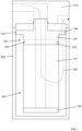
- Figure 1 is a diagrammatic illustration of a filter assembly 100, in a housing 200, according to an exemplary embodiment of the disclosure.
- the flow from the head 210 to the filter assembly 100 is concentric with the filter element 110.
- the end cap 120 may be non-concentric with the filter element 110.
- Figure 1 is a very schematic diagrammatic illustration, while Figures 2 to 6 are more detailed diagrammatic illustrations.
- the filter element 110 may comprise a coalescence filter or an activated carbon filter.
- Figure 1 illustrates schematic how the filter assembly 100 is mounted in a housing 200.
- Figure 1 shows the principals how the filter assembly 100 may be used for filtering a fluid.
- the filter assembly 100 has an end cap 120 that releasably connects the filter assembly 100 to a housing 200 and to a head 210.
- a fluid may flow as illustrated by the dotted arrow 230 through the head 210, into and through the end cap 120, into the filter element 110, out from the filter element 110, and back up out through the head 210.
- the fluid may for example be air, such as compressed air, and the filter element 110 may for example be for filtering out particles, aerosols, and vapours from the air.
- the end cap 120 comprises a first part 122 and a second part 124 releasably connectable to each other.
- a sealing element 128, such as for example an O-ring, may be used for sealing between the first part 122 and the second part 124.
- the housing 200 may be shaped as a bowl 200 that surrounds the filter element 110.
- the housing 200 may be attachable to the head 210.
- the end cap 120 may connect to the head 210 for directing the flow of fluid to the filter element, and the end cap 120 may also connect to the housing 200 to position the filter element 110 in the housing 200.
- the housing 200 may be substantially shaped as a hollow cylinder with one end closed and the other end releasable connected to the head 210.
- the filter element 110 may be, in normal usage, arranged as illustrated in figure 1 . That is, the filter element 110 may be shaped substantially as a hollow cylinder with the axis of the hollow cylinder being substantially aligned with gravity, and the end cap 120 being above the filter element 110.
- the filter assembly 100 is shown.
- the filter assembly in figures 2 to 6 is in principal almost similar to that one in figure 1 .
- a filter assembly for filtering a fluid, preferably compressed air, is shown.
- the filter assembly 100 comprises a filter element 110 with an end cap 120.
- the end cap 120 is configured for guiding the fluid to the filter element 110 and positioning, holding, the filter 100 in a housing 200.
- the end cap 120 comprises a first part 122 and a second part 124 releasably connectable to each other by an interlocking mechanism 130. This allows the first part 122 and the second part 124 to be connected to each other and to be disconnected from each other.
- the first part 122 is attached to the filter element 110.
- the second part 124 is releasably attachable to the housing 200 and configured for positioning the filter 100 within the housing 200. This allows the filter element 100 with the first part 122 to be exchanged while the second part 124 can be reused.
- the first part 122 is permanently attached to the filter element 110.
- the second part 124 is releasably attachable to the housing 200 and only the second part 124 is configured for positioning the filter assembly 100 within the housing 200. It is preferred that the second part 124 alone releasably attaches to, and positions the filter assembly in, the housing 200.
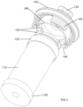
- Figures 2 , 3 , 5, and 6 illustrate that the second part 124 may comprise an outer circumferential edge 140.
- the outer circumferential edge 140 may comprise an attachment mechanism 142 for releasably attach the second part 124 to the housing 200.
- the attachment mechanism 142 may be threads, a snap connection, or a bayonet connection.
- the attachment mechanism 142 may comprising one or more openings 144. This allows for a secure and reliable positioning of the filter assembly 100 within the housing 200. It also allows for the filter element 100 with the first part 122 to be exchanged when the filter needs changing, while the second part 124 can be reused.
- the one or more openings 144 may open up, remove, parts of the attachment mechanism 142.
- the one or more openings 144 may allow fluid to pass through the second part 124 and the attachment mechanism 142.
- a circumferential thread 142 may be interrupted with the one or more openings 144. Viewed in the circumferential direction, the one or more openings 144 may be substantially equal, or larger, in distance to the attachment mechanism 142.
- Figures 2 , 3 , 5, and 6 show four openings 144, but there may be one, two, three, five, six, seven, or eight openings. These openings allow for a better flow of fluid and therefore reduces pressure loss.
- the attachment mechanism 142 may have a substantial T-shaped form, as a segment with the attachment mechanism 142 on the outside and the leg of the T attached to an inner ring 148 of the second part 124.
- the inner ring 148 may support the attachment mechanism 142 on its outside and support the interlocking mechanism 130 on its inside.
- the interlocking mechanism 130 may be within, and substantially in the same plane as, the attachment mechanism 142. This is to be understood such that the attachment mechanism 142 and the interlocking mechanism 130 are substantially in the same radial plane in relation to a central axis of the filter assembly. This configuration allows the filter element 100 to be larger since the interlocking mechanism 130 and the attachment mechanism 142 are in the same plane, rendering the end cap 120 compact.
- figure 3 shows how the interlocking mechanism 130 is inside the attachment mechanism 142. This improves the filtration efficiency since there is more space for a large filter element 100.
- the end cap 120 may further comprise a sealing element 128 for sealing between the first part 122 and the second part 124.
- the sealing element 128 may be an O-ring. This forces the fluid to pass through the filter and frequent reuse of the second part 124.
- the interlocking mechanism 130 may comprise a bayonet connection.
- the bayonet connection may be a fastening mechanism comprising of a cylindrical male side with one or more radial protrusions 130 and a female receptor with matching protrusions 130 with openings to allow the two parts to be locked together.
- the interlocking mechanism 130 may comprise a threaded connection, such as a threaded screw connection.
- the first part 122 may comprise a thread facing outwards in a radial direction
- the second part 124 may comprise a complimentary thread facing inwards in a radial direction. This would allow the first part 122 and the second part 124 to be screw connected to each other.
- the screw threads may have two, three, or four starts.
- the interlocking mechanism 130 may comprise clamps and/or clips.
- the first part 122 and the second part 124 may be snap fitted to each other, or a clamp mechanism may be used to clamp them together.
- a latch clamp may be used.
- Clips may for example be flexible elements that can snap into a locking position, a form shaped fitting, and interlock the first part 122 and the second part 124.
- the figures illustrate a preferred embodiment wherein the filter element 110 is substantially shaped as a hollow cylinder, and the first part 122 and the second part 124 comprise openings for guiding the fluid to the filter element 110.
- the openings may be central and co-axial openings for guiding the fluid to an inside of the filter element 110, as illustrated with the flow of fluid by the dotted arrow 230 in figure 1 .
- the second part 124 may comprise a partly circumferential thread 142 for positioning the filter assembly 100.
- the partly circumferential thread 142 may have a larger circumference, or a larger radius, then the filter element 110. This allows for a secure positioning and reduced pressure loss of the air treatment.
- the filter element 110 may comprises a second end cap 150. This is best illustrated in figures 1 to 4 .
- the filter element 110 may be arranged between the first part 122 and the second end cap 150.
- the second end cap 150 may close of the hollow cylindrical filter element 110 at one end, while the end cap 120 may guide, directly from the head 210, fluid towards the centre of the hollow cylindrical filter element 110 at the other, opposite, end.
- an adapter 124 is disclosed.
- This adapter is to be used in a filter assembly, preferably the filter assembly according to any one of the embodiments disclosed herein, wherein the adapter is only the second part 124.
- Such an adapter makes it possible to replace the filter element 110 frequently, without having to replace the adapter 124.
- the adapter 124, the second part 124, may be reused several times.
- the adapter may be configured to be reused for up to one hundred times.
- the figures illustrate an adapter for a filter assembly, preferably the filter assembly disclosed herein.
- the adapter 124 comprises an interlocking mechanism 130 and an outer circumferential edge 140 with an attachment mechanism 142, as described herein.
- the interlocking mechanism 130 is configured to be releasably connect the adapter 124 to a first part, preferably the first part 122.
- the outer circumferential edge 140 comprising an attachment mechanism 142 for releasably attach the adapter 124 to a housing 200, the attachment mechanism 142 comprising one or more openings 144.
- the interlocking mechanism 130 is within, and substantially on the same plane as, the attachment mechanism 142. Reference is made to the description of the second part 124 that may be regarded as an adapter 124 for attaching the filter element 110 to a housing 200.
- a kit comprising the filter assembly described herein.
- the kit comprises on one hand the filter element 110 and the first part 122 attached to the filter element 110, as described herein.
- the kit comprises on the other hand the second part 124, as described herein.
- This allows the filter element 110 and the first part 122 attached to the filter element 110 to be handled separately, for example, sold and stored, independently of the second part 124.
- This also allows the second part 124 be handled separately, for example, sold and stored, independently of filter element 110 and the first part 122. This gives the possibility to reuse the second part 124 several times, even if the filter element 110 must be discharged each time the filter element 110 needs to be changed.
- a kit may comprise the filter assembly according to any one of the embodiments described herein.
- the kit may comprise on one hand a first part 122 attached to a filter element 110; and on the other hand a second part 124 being releasably attachable to a housing 200 and configured for positioning the filter assembly 100 within the housing 200.
- the first part 122 and the second part 124 are releasably connectable to each other by an interlocking mechanism 130.
- the second part 124 may comprise an outer circumferential edge 140, the outer circumferential edge 140 comprising an attachment mechanism 142 for releasably attach the second part 124 to the housing 200, the attachment mechanism 142 comprising one or more openings 144.
- the interlocking mechanism 130 may be within, and substantially in the same plane as, the attachment mechanism 142. This has also been disclosed earlier herein.
- an air treatment system comprises the filter assembly described herein.
- Such an air treatment system may comprise a compressor for compressing air and subsequently filtering the compressed air, according to any one of the preceding embodiments.
- the air treatment system may comprise a compressor, the housing 200, the head 210, and the filter assembly.
- the air treatment system may further include valves, sensors, and fluid conduits.
Landscapes
- Chemical & Material Sciences (AREA)
- Chemical Kinetics & Catalysis (AREA)
- Physics & Mathematics (AREA)
- Geometry (AREA)
- Filtering Of Dispersed Particles In Gases (AREA)
Priority Applications (4)
| Application Number | Priority Date | Filing Date | Title |
|---|---|---|---|
| EP23191331.0A EP4509201A1 (de) | 2023-08-14 | 2023-08-14 | Filteranordnung |
| CA3249101A CA3249101A1 (en) | 2023-08-14 | 2024-07-19 | Filter assembly |
| US18/803,021 US20250058259A1 (en) | 2023-08-14 | 2024-08-13 | Filter assembly |
| CN202411106614.8A CN119488765A (zh) | 2023-08-14 | 2024-08-13 | 过滤器组件 |
Applications Claiming Priority (1)
| Application Number | Priority Date | Filing Date | Title |
|---|---|---|---|
| EP23191331.0A EP4509201A1 (de) | 2023-08-14 | 2023-08-14 | Filteranordnung |
Publications (1)
| Publication Number | Publication Date |
|---|---|
| EP4509201A1 true EP4509201A1 (de) | 2025-02-19 |
Family
ID=87571845
Family Applications (1)
| Application Number | Title | Priority Date | Filing Date |
|---|---|---|---|
| EP23191331.0A Pending EP4509201A1 (de) | 2023-08-14 | 2023-08-14 | Filteranordnung |
Country Status (4)
| Country | Link |
|---|---|
| US (1) | US20250058259A1 (de) |
| EP (1) | EP4509201A1 (de) |
| CN (1) | CN119488765A (de) |
| CA (1) | CA3249101A1 (de) |
Cited By (1)
| Publication number | Priority date | Publication date | Assignee | Title |
|---|---|---|---|---|
| WO2025240899A1 (en) * | 2024-05-17 | 2025-11-20 | Donaldson Company, Inc. | Filter elements and assemblies |
Citations (5)
| Publication number | Priority date | Publication date | Assignee | Title |
|---|---|---|---|---|
| WO1999030799A1 (en) | 1997-12-15 | 1999-06-24 | Domnick Hunter Limited | Filter assembly |
| EP2129448A1 (de) | 2007-03-02 | 2009-12-09 | Kaeser Kompressoren GmbH | Adapter für einen druckluft-filter und verwendung eines solchen |
| WO2013003769A2 (en) * | 2011-06-30 | 2013-01-03 | Donaldson Company, Inc. | Air/oil separator assemblies; components; and, methods |
| US20200179840A1 (en) * | 2018-12-11 | 2020-06-11 | A.L. Filter Co., Ltd. | Fluid filter element for circular locking engagement with a filter support |
| US11426691B2 (en) * | 2016-11-04 | 2022-08-30 | Donaldson Company, Inc. | Filter elements, air cleaner assemblies, and methods of use and assembly |
-
2023
- 2023-08-14 EP EP23191331.0A patent/EP4509201A1/de active Pending
-
2024
- 2024-07-19 CA CA3249101A patent/CA3249101A1/en active Pending
- 2024-08-13 US US18/803,021 patent/US20250058259A1/en active Pending
- 2024-08-13 CN CN202411106614.8A patent/CN119488765A/zh active Pending
Patent Citations (5)
| Publication number | Priority date | Publication date | Assignee | Title |
|---|---|---|---|---|
| WO1999030799A1 (en) | 1997-12-15 | 1999-06-24 | Domnick Hunter Limited | Filter assembly |
| EP2129448A1 (de) | 2007-03-02 | 2009-12-09 | Kaeser Kompressoren GmbH | Adapter für einen druckluft-filter und verwendung eines solchen |
| WO2013003769A2 (en) * | 2011-06-30 | 2013-01-03 | Donaldson Company, Inc. | Air/oil separator assemblies; components; and, methods |
| US11426691B2 (en) * | 2016-11-04 | 2022-08-30 | Donaldson Company, Inc. | Filter elements, air cleaner assemblies, and methods of use and assembly |
| US20200179840A1 (en) * | 2018-12-11 | 2020-06-11 | A.L. Filter Co., Ltd. | Fluid filter element for circular locking engagement with a filter support |
Cited By (1)
| Publication number | Priority date | Publication date | Assignee | Title |
|---|---|---|---|---|
| WO2025240899A1 (en) * | 2024-05-17 | 2025-11-20 | Donaldson Company, Inc. | Filter elements and assemblies |
Also Published As
| Publication number | Publication date |
|---|---|
| CN119488765A (zh) | 2025-02-21 |
| US20250058259A1 (en) | 2025-02-20 |
| CA3249101A1 (en) | 2025-06-05 |
Similar Documents
| Publication | Publication Date | Title |
|---|---|---|
| EP1126159B1 (de) | Befestigungssytem für ökologische Filterpatrone und Filterelement | |
| US20250058259A1 (en) | Filter assembly | |
| EP2976144B1 (de) | Filteranordnung | |
| AU2015209639B2 (en) | Filter element having end cap seal and filter assembly | |
| US4052317A (en) | Filtering equipment | |
| EP4126292B1 (de) | Filter und filterbasishaltesystem | |
| US20200316632A1 (en) | Offset showerhead filter | |
| US12290770B2 (en) | Filtration system with bypass and filtering configurations, and components and methods of operation thereof | |
| AU2024264036A1 (en) | Filter assemblies and related filter elements | |
| EP2911762B1 (de) | Ölfilter | |
| US12350612B2 (en) | Multiple threaded connector for filter | |
| CN108404675B (zh) | 内压式中空纤维膜组件 | |
| EP4308265B1 (de) | Filtergehäuse für anschraubbare oder anschraubbare patronenanordnungen | |
| EP4245394A1 (de) | Einstufiges filtrationssystem | |
| EP3434333B1 (de) | Schlauchverbindermontagemechanismus in strombetriebenem luftreinigendem atemgerätgehäuse | |
| CN210620334U (zh) | 一种滤膜组件 | |
| CN219984061U (zh) | 一种易接管净水器滤瓶 | |
| CN217794951U (zh) | 净水器 | |
| CN213655978U (zh) | 金属法兰接头 | |
| CN219579994U (zh) | 一种可固定滤袋的过滤器 | |
| US20180304183A1 (en) | Air Filter with Minimal Pressure Loss | |
| EP4497489B1 (de) | Befestigungssystem für ventile zur reinigung von industriefiltern | |
| CN213132245U (zh) | 大通量精密滤水器进水组件 | |
| CN214680345U (zh) | 一种原代细胞过滤装置 | |
| US20250262573A1 (en) | Filter assembly with floating seal interface |
Legal Events
| Date | Code | Title | Description |
|---|---|---|---|
| PUAI | Public reference made under article 153(3) epc to a published international application that has entered the european phase |
Free format text: ORIGINAL CODE: 0009012 |
|
| STAA | Information on the status of an ep patent application or granted ep patent |
Free format text: STATUS: REQUEST FOR EXAMINATION WAS MADE |
|
| 17P | Request for examination filed |
Effective date: 20230814 |
|
| AK | Designated contracting states |
Kind code of ref document: A1 Designated state(s): AL AT BE BG CH CY CZ DE DK EE ES FI FR GB GR HR HU IE IS IT LI LT LU LV MC ME MK MT NL NO PL PT RO RS SE SI SK SM TR |