EP4509232A1 - Tendeur de tamis pour tendre un revêtement de tamis - Google Patents
Tendeur de tamis pour tendre un revêtement de tamis Download PDFInfo
- Publication number
- EP4509232A1 EP4509232A1 EP24180365.9A EP24180365A EP4509232A1 EP 4509232 A1 EP4509232 A1 EP 4509232A1 EP 24180365 A EP24180365 A EP 24180365A EP 4509232 A1 EP4509232 A1 EP 4509232A1
- Authority
- EP
- European Patent Office
- Prior art keywords
- screen
- tensioning
- clamping
- edge
- tensioner
- Prior art date
- Legal status (The legal status is an assumption and is not a legal conclusion. Google has not performed a legal analysis and makes no representation as to the accuracy of the status listed.)
- Pending
Links
Images

Classifications
-
- B—PERFORMING OPERATIONS; TRANSPORTING
- B07—SEPARATING SOLIDS FROM SOLIDS; SORTING
- B07B—SEPARATING SOLIDS FROM SOLIDS BY SIEVING, SCREENING, SIFTING OR BY USING GAS CURRENTS; SEPARATING BY OTHER DRY METHODS APPLICABLE TO BULK MATERIAL, e.g. LOOSE ARTICLES FIT TO BE HANDLED LIKE BULK MATERIAL
- B07B1/00—Sieving, screening, sifting, or sorting solid materials using networks, gratings, grids, or the like
- B07B1/46—Constructional details of screens in general; Cleaning or heating of screens
- B07B1/48—Stretching devices for screens
Definitions
- the invention relates to a screen tensioner for tensioning a screen lining in a screening machine, wherein the screen tensioner has a rod-like or profile-like tensioning section which has a fastening section in the region of its two longitudinal ends.
- the invention further relates to a screening machine with a screen tensioner.
- DE 25 01 750 A discloses a screening machine with a screen box.
- screen coverings There are three screen coverings arranged one above the other. These screen coverings are designed as grid floors that have a bevel at their long ends. The bevels are bent in the direction from the top of the screen covering to the bottom. The bevels are V-shaped in cross-section.
- Screen tensioners which are designed in the form of rods, engage in these bevels.
- the screen tensioner has a clamping projection on one clamping side that forms a clamping edge. This clamping edge rests on the bottom of the bevel.
- the screen tensioners have fastening sections on the long ends that are acted upon by clamping elements in order to tension the screen covering in the screen box.
- the screen tensioner When the screen tensioner is tensioned in this known device, the screen tension is uneven over the length of the screen tensioner. Accordingly, there are screen areas that are subject to greater pre-tension than neighboring screen areas. The different screen tension leads to vibration behavior of the screen lining, which results in premature failure before the maximum service life of the screen lining is reached.
- EP 0 238 455 A2 discloses a screening machine in which a screening panel is pre-tensioned with a screen tensioner in the form of a hollow profile.
- the screen tensioner has a molded-on clamping projection that forms a clamping edge.
- the object of the invention is to provide a user with the possibility to easily tension different types of screen coverings.
- the clamping section of the screen clamp has a first clamping projection in the region of a first clamping side, which forms a first clamping edge, and a second clamping projection on an opposite second clamping side, which forms a second clamping edge, that the first clamping edge and the second clamping edge extend between the two fastening sections, and that the first clamping edge forms a first and the second clamping edge forms a second clamping contour, and that the first and the second clamping contours have different geometries.
- the screen tensioner has two clamping edges, it can either bring one or the other clamping edge into clamping engagement with the screen lining to be installed.
- the clamping edges are geometrically designed differently and are therefore designed for an individual screen lining. This means that the user can use one screen tensioner to clamp two different screen linings in one screening device without having to change the screen tensioner. The user can use the same screen tensioner, which can preferably be used in two different mounting positions. This makes it much easier for him to maintain the screening machine.
- one of the two clamping edges can be convex with a curvature extending between the two fastening sections, and the other clamping edge can be convex or concave with a curvature extending between the two fastening sections, or the other clamping edge can run in a straight line between the two fastening sections. If one clamping edge is convex and the other clamping edge is concave, then it is advantageous if the contours followed by the two clamping edges differ from one another, and it is preferable that the amount of elevation is different on both sides.
- the curvature of the convex clamping edge of one clamping projection can be designed for a corresponding screen covering in order to clamp it in the screen box with as uniform a tension as possible.
- the clamping edge with the furthest protruding area first comes into contact with the associated fastening edge of the screen covering and clamps it here.
- the screen tensioner is further tensioned, it deforms elastically, with the remaining areas of the clamping edge gradually coming into contact with the screen covering and clamping it here.
- uniform tension is achieved across the entire width of the screen covering. This takes into account the knowledge that evenly tensioned screen coverings have a longer service life and that inherent properties of the screen covering, such as self-cleaning, are supported.
- the degree of curvature can be designed to suit the corresponding screen lining in order to pre-press it evenly.
- this type of screen tensioner is suitable for screen coverings that require greater tension on two sides of the covering. These come into contact with the concave geometry of the screen tensioner first.
- the screen tensioner can be used on the straight edge for screen surfaces that have only a small require screen tension.
- the second tensioning edge is therefore intended for light, delicate screen coverings, for example. These require less pre-tensioning. Due to the lower pre-tensioning force, a strongly curved tensioning edge is not elastically deformed to the same extent, so that the outer areas of the light screen covering do not come into contact with the tensioning edge and remain untensioned.
- the clamping contours of the first clamping edge and the second clamping edge each have contour end sections in the area of their ends facing the fastening sections and a contour center between the contour end sections, so that when the clamping edge is projected into the central transverse plane (Q), the contour center of at least one of the clamping edges is offset with a maximum elevation in or against the clamping direction relative to the contour end sections.
- the clamping edge is convexly or concavely curved, with the amount of elevation resulting from the size of the recess if the clamping edge is concavely curved.
- the amount of elevation of the first clamping edge differs from the elevation of the second clamping edge. In this way, two different clamping contours can easily be achieved.
- the clamping contours of the two clamping edges can be both convex or both concave or one clamping edge can be convex and the other clamping edge can be concave.
- one tension edge can be convex or concave and the other straight.
- the amount of the overhang (H) is less than or equal to 25mm.
- Such screen clamps are suitable for use in screening machines that are used in conjunction with rock crushers or crushers for processing mineral material.
- the maximum length of the screen tensioner is preferably less than 1800 mm.
- the clamping section has an upper side and a lower side and that the screen clamp is designed, at least in the region of its clamping section, symmetrically to the central transverse plane running between the upper side and the lower side.
- This screen clamp is easy to install and can be mounted on a cover and has a compact design.
- first and/or second clamping edge is provided with a rounding extending between the top and bottom of the clamping section, the stress peaks transferred to the screen lining are avoided or reduced.
- assembly is made easier in that at least one of the fastening sections has at least one identification marking which is assigned to the first and/or the second clamping side, wherein the identification marking is preferably designed as a recess and more preferably is incorporated into the longitudinal end of the fastening section.
- a possible variant of the invention can be such that the convex or concave clamping edge is circular or elliptical or is composed of several contour sections. This allows the clamping edge to be individually adapted to a screen covering. Preferably, the clamping edge follows a continuously differentiable function in the direction between the two fastening sections in order to achieve a tension-optimized structure.
- the object of the invention is also achieved with a screening machine with a screening device which has a screening lining, wherein a screening tensioner according to one of claims 1 to 8 acts on the screening lining.
- the screen covering has a fastening edge on at least one of its longitudinal ends, which is designed in the form of an angled portion, and that the screen tensioner engages in the angled portion with one of its clamping projections.
- FIG. 1 shows a screening machine 10 according to the invention.
- This screening machine 10 is designed as a mobile screening machine 10. It is also conceivable that the invention is used in a stationary screening machine.
- the screening machine 10 has a chassis 11, which is supported by undercarriages 11.1 in order to be able to move the screening machine.
- the screening machine 10 preferably has a feed hopper 12. Material to be screened can be filled into the feed hopper 12 by means of a wheel loader.
- the feed hopper 12 has a transport device, for example a vibrating chute, a conveyor belt, a feed belt, or a bunker discharge belt, by means of which the fed material can be conveyed to a feed belt 13.
- the feed belt 13 can be designed as an endlessly rotating conveyor belt.
- the feed belt 13 conveys the material to be screened to a screening device which has a screen box 60.
- the screening device serves to screen at least two fractions from the supplied material.
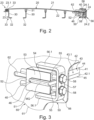
- the screening device has at least one screen lining 20, as Figure 2 shows.
- Figure 1 further illustrates that the sieve box 60 has side walls 61 which run in the longitudinal direction of the sieve.
- the screen box 60 is mounted on a stationary screen box support 64 by means of spring elements 63.
- the screen box 60 can be set into vibration by means of a drive 65 in order to screen the material.
- the screening device is assigned at least one discharge belt 14.1, 14.2 or at least one fine grain or stockpile belt 15.
- two discharge belts 14.1, 14.2 and one fine grain or stockpile belt 15 are used. Accordingly, two screen linings 20 are installed in the screening device.
- the material to be screened is fed onto the upper screen layer 20.
- the material that falls through the upper screen layer 20 reaches the screen layer 20 below.
- Material that does not fall through the upper screen layer 20 reaches one of the two discharge belts 14.1, 14.2.
- the material that does not fall through the second screen layer 20 reaches the second discharge belt 14.1, 14.2.
- the material which falls through both screen linings 20 in the form of fine grain material reaches the fine grain or stockpile belt 15.
- the two discharge belts 14.1, 14.2 and the fine grain or stockpile belt 15 each convey the grain fractions fed to them to stockpiles 16.
- FIG. 2 shows a schematic representation of a section of the screening device.
- support elements 30 are installed in the screening box 60, which support the screening lining 20.
- the support elements 30 have a fastening foot 32 with which they are fixed in place in the screening box 60.
- damping elements 31 are placed on one side of the support elements 30 in an exchangeable manner.
- the damping elements 31 support the screening lining 20 in the area of the underside 22 of the screening device.
- the support elements 30 can be arranged and aligned with their damping elements 31 in such a way that the screen covering 20 resting on the damping elements 31 forms an arcuate contour in the longitudinal direction of the screen, as Figure 2 shows.
- the left-hand support element 30 has a holder attachment 33 at its end facing away from the fastening foot 32.
- the screen lining 20 is held replaceably on the holder attachment 33 by a fastening edge 23.
- the sieve covering 20 is designed as a surface element and has a sieve top 21 opposite the sieve bottom 22. It may be the case that the fastening edge 23 is bent from an end section 23.1 of the sieve covering 20 in order to form an angled portion 23.2. The retaining projection 33 engages in this angled portion 23.2.
- the sieve covering 20 has a further fastening edge 24, which is essentially constructed identically to the fastening edge 23. Accordingly, an angled portion 24.2 is bent off the sieve covering 20 at the opposite end section 24.1.
- the screen lining 20 must be positioned in the screen box 60 in the longitudinal direction (i.e. Figure 2 from left to right).
- a screen tensioner 40 is used.
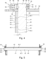
- the Figures 3 and 5 illustrate that the screen tensioner 40 is essentially rectangular in cross section.
- the screen tensioner 40 can therefore have a rod-shaped geometry.
- the screen tensioner 40 has a central tensioning section 41 which extends between two end fastening sections 46.
- the clamping section 41 has clamping projections 42, 43 on its opposite longitudinal sides.
- the first clamping projection 42 has a first clamping edge 42.1.
- the second clamping projection 43 has a second clamping edge 43.1.
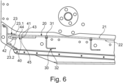
- the first clamping edge 42.1 is convexly curved between the two fastening sections 46, such as Figure 4 illustrated.
- Figure 4 shows a horizontal section through the central transverse plane MQ of the screen tensioner 40.
- the central transverse plane MQ and thus the cutting plane according to Figure 4 is in Figure 3 marked.
- the first clamping edge 42.1 forms a clamping contour.
- This clamping contour has contour end sections 49.1 at its longitudinal ends and a contour center 49.2 in the middle between the contour end sections 49.1.
- the projection of the first clamping edge 42.1 into the central transverse plane MQ in the area of the contour center 49.2 has a maximum camber H.
- This maximum camber H results from the fact that the contour center 49.2 is offset in the clamping direction compared to the contour end sections 49.1 due to the convex curvature.
- the camber H is less than 25 mm.
- the second clamping edge 43.1 which is opposite the first clamping edge 42.1, also forms a clamping contour.
- This clamping contour again forms contour end sections 49.1 at opposite ends, which face the fastening sections 46.
- a contour center 49.2 is formed in the middle between the contour end sections 49.1.
- the projection of the second clamping edge 43.1 into the central transverse plane MQ runs straight between the two fastening sections 46, as Figure 4
- the second clamping edge 43.1 is convexly curved and has a maximum camber which preferably deviates from the maximum camber H of the first clamping edge 42.1.
- the second clamping edge 43.1 forms a concave contour.
- a negative camber H results in the contour center 49.2. It is preferably the case that the amount of the two cambers H of the two clamping edges 42.1, 43.1 differs from one another.
- the screen tensioner 40 is constructed symmetrically to the central transverse plane MQ.
- the screen tensioner 40 engages with its first clamping projection 42 in the Figure 2 shown right-hand bend 24.2.
- the sieve tensioner 40 rests with its first clamping edge 42.1 on the base section 42.3 below the sieve underside 22 resulting from the bend 24.2.
- the clamping projection 42 is thus at least partially enclosed between the sieve underside 22 and the bend 24.2.
- the sieve tensioner 40 extends on opposite sides with its fastening sections 46 through passages 62 in the associated side walls 61 of the sieve box 60, as Figure 3 shows clearly. Accordingly, the fastening sections 46 protrude on the outside beyond the side walls 61 of the sieve box 60. In the area of the passages 62 of the sieve box 60, tensioning devices 50 are arranged, with which the sieve tensioner 40 can be adjusted in the tensioning direction along the central transverse plane MQ.
- the clamping devices 50 each have a stationary support bearing 56, which is preferably firmly connected to the side wall 61, for example welded.
- the support bearing 56 can be designed in such a way that it has a holder 57 to which at least one bearing piece 56.1 is connected, preferably molded.
- the support bearing 56 can be stably connected to the associated side wall 61 by means of the two bearing pieces 56.1 and the holder 57.
- the clamping device 50 also has a clamping piece 52 by means of which the screen clamp 40 is positively engaged in order to move it in the clamping direction. It can be the case that legs 51, 53 are connected, preferably molded, to the clamping piece 52 on opposite sides.
- the leg 53 overlaps the top and the leg 51 the bottom of the screen tensioner 40, so that the screen tensioner 40 is prevented from moving in these directions when it is tensioned.
- At least one clamping screw 58 is used, by means of which the clamping piece 52 can be continuously adjusted.
- the clamping screw 58 is supported on the holder 57.
- the stepless adjustment of the clamping piece 52 can be achieved via a threaded connection.
- each of the legs 51, 53 has a threaded receptacle 55.
- the holder 57 has two passages through which the clamping screws 58 are inserted and screwed into the threaded receptacles 55.
- the Figures 4 and 5 show an assembly position in which the screen tensioner 40 is in an unclamped position. If the clamping screws 58 of the two clamping devices 50 are now tightened, the first clamping edge 42.1 hits the base section 24.3 in the area of its contour center 49.2 with its maximum elevation H. (see Figure 4 ) of the bend 42.1. If the clamping screws 58 are now tightened further, the screen covering 20 is tensioned starting from the contour center 49.2. This results in a counterforce of the screen covering 20, which acts on the screen tensioner 40. Due to this counterforce, the screen tensioner 40 is bent so that the 1st clamping edge 42.1 continuously rests against the base section 24.3 towards the two contour end sections 49.1. The clamping force is thus gradually applied to the screen covering 20. The convexly curved contour of the first clamping edge 42.1 thus causes a uniform tension of the screen covering 20.
- the uniform tension can be estimated by a sound test at individual points on the screen covering 20. To do this, the screen covering 20 is struck at different points. The tension state can be determined from the sound generated.
- the screen lining 20 is dismantled in the reverse order. To do this, first loosen the clamping screw 58, then the screen tensioner 40 can be moved in the passages 62 until it is disengaged from the bend 24.2. The screen lining 20 can then be lifted upwards and moved in the opposite direction to the clamping direction so that the bend 23.2 is disengaged from the retaining projection 33 (see Figure 2 ). The screen lining 20 can then be lifted out of the screen box 60 and replaced with a new screen lining 20.
- the screen tensioner 40 can be adapted to this second screen covering 20, for which it only has to be rotated so that the second Tensioning edge 42.1 engages with the associated bend 24.2 of this screen covering 20. The screen tensioner 40 can then be clamped again in the same way to the new screen covering 20 as explained above.
- the screen tensioner 40 can be used to optimally tension two different screen coverings 20.
- an identification marking 48 can be provided in the area of at least one fastening section 46.
- the identification marking 48 is in Figure 4 shown by way of example.
- the identification marking 48 is incorporated into the longitudinal end of the fastening section 48.
Landscapes
- Combined Means For Separation Of Solids (AREA)
Applications Claiming Priority (1)
| Application Number | Priority Date | Filing Date | Title |
|---|---|---|---|
| DE102023121746.1A DE102023121746B3 (de) | 2023-08-15 | 2023-08-15 | Siebspanner zum Spannen eines Siebbelags |
Publications (1)
| Publication Number | Publication Date |
|---|---|
| EP4509232A1 true EP4509232A1 (fr) | 2025-02-19 |
Family
ID=91432906
Family Applications (1)
| Application Number | Title | Priority Date | Filing Date |
|---|---|---|---|
| EP24180365.9A Pending EP4509232A1 (fr) | 2023-08-15 | 2024-06-06 | Tendeur de tamis pour tendre un revêtement de tamis |
Country Status (4)
| Country | Link |
|---|---|
| US (1) | US12605742B2 (fr) |
| EP (1) | EP4509232A1 (fr) |
| CN (1) | CN119489036A (fr) |
| DE (1) | DE102023121746B3 (fr) |
Families Citing this family (2)
| Publication number | Priority date | Publication date | Assignee | Title |
|---|---|---|---|---|
| DE102023121746B3 (de) * | 2023-08-15 | 2024-10-17 | Kleemann Gmbh | Siebspanner zum Spannen eines Siebbelags |
| DE102023131848B3 (de) * | 2023-11-15 | 2024-12-12 | Kleemann Gmbh | Siebmaschine mit einem Siebkasten |
Citations (5)
| Publication number | Priority date | Publication date | Assignee | Title |
|---|---|---|---|---|
| FR1017072A (fr) * | 1950-05-03 | 1952-12-01 | Tamis vibrant allongé | |
| US2812062A (en) * | 1952-07-10 | 1957-11-05 | Thomas W Hannon | Electrically heated screen construction |
| DE2501750A1 (de) | 1974-01-26 | 1975-07-31 | Powerscreen Int Ltd | Schuettelsieb |
| EP0238455A2 (fr) | 1986-03-17 | 1987-09-23 | F.lli DE POLI S.r.l. | Tamis vibrant simple ou multiple |
| CA1275975C (fr) * | 1984-11-06 | 1990-11-06 | Karl H. Eggerstedt | Methode et dispositif de decolmatage des tissus-tamis, plus particulierement ceux des materiels de tamisage vibratoires |
Family Cites Families (14)
| Publication number | Priority date | Publication date | Assignee | Title |
|---|---|---|---|---|
| US3406823A (en) * | 1966-03-25 | 1968-10-22 | Orville Simpson Company | Releasable screen tensioning and connecting means |
| US3608482A (en) * | 1969-10-31 | 1971-09-28 | American Screen Process Equip | Locking bar for screen-printing frame |
| DE3239319A1 (de) * | 1982-10-23 | 1984-04-26 | Elmar Dr. 8000 München Messerschmitt | Klemmvorrichtung, insbes. fuer siebdruckrahmen |
| DE4329879A1 (de) * | 1993-09-03 | 1995-03-09 | Fraembs & Freudenberg Gmbh | Siebmaschine |
| US6431366B2 (en) * | 1999-06-16 | 2002-08-13 | Derrick Manufacturing Corporation | Vibratory screening machine with stacked and staggered screening units |
| AU2003260777A1 (en) * | 2002-10-17 | 2004-05-04 | Lucas, Brian, Ronald | Vibratory separator |
| CN100571898C (zh) * | 2003-12-17 | 2009-12-23 | 安曼瑞士股份公司 | 滤网插件在振动筛选机中的固定方法和沥青混合设备的振动筛选机 |
| US20070108106A1 (en) * | 2005-11-16 | 2007-05-17 | Burnett George A | Shakers with primary and auxiliary vibrators |
| US7578394B2 (en) * | 2007-03-21 | 2009-08-25 | Derrick Corporation | Method and apparatuses for screening |
| US8002116B1 (en) * | 2009-10-09 | 2011-08-23 | Cato James N | Vibrating stackable fine industrial mineral high speed screening unit |
| US10843231B2 (en) * | 2017-06-01 | 2020-11-24 | Terex Usa, Llc | Method and apparatus for applying tension to a screen cloth on a vibrating screening machine |
| CN114682487B (zh) * | 2022-04-09 | 2023-01-24 | 合肥市新庆申新型建材有限公司 | 一种新型建材制造用输料设备 |
| DE102023121746B3 (de) * | 2023-08-15 | 2024-10-17 | Kleemann Gmbh | Siebspanner zum Spannen eines Siebbelags |
| DE102023131848B3 (de) * | 2023-11-15 | 2024-12-12 | Kleemann Gmbh | Siebmaschine mit einem Siebkasten |
-
2023
- 2023-08-15 DE DE102023121746.1A patent/DE102023121746B3/de active Active
-
2024
- 2024-06-06 EP EP24180365.9A patent/EP4509232A1/fr active Pending
- 2024-06-14 US US18/743,221 patent/US12605742B2/en active Active
- 2024-06-24 CN CN202410816884.1A patent/CN119489036A/zh active Pending
Patent Citations (5)
| Publication number | Priority date | Publication date | Assignee | Title |
|---|---|---|---|---|
| FR1017072A (fr) * | 1950-05-03 | 1952-12-01 | Tamis vibrant allongé | |
| US2812062A (en) * | 1952-07-10 | 1957-11-05 | Thomas W Hannon | Electrically heated screen construction |
| DE2501750A1 (de) | 1974-01-26 | 1975-07-31 | Powerscreen Int Ltd | Schuettelsieb |
| CA1275975C (fr) * | 1984-11-06 | 1990-11-06 | Karl H. Eggerstedt | Methode et dispositif de decolmatage des tissus-tamis, plus particulierement ceux des materiels de tamisage vibratoires |
| EP0238455A2 (fr) | 1986-03-17 | 1987-09-23 | F.lli DE POLI S.r.l. | Tamis vibrant simple ou multiple |
Also Published As
| Publication number | Publication date |
|---|---|
| US12605742B2 (en) | 2026-04-21 |
| DE102023121746B3 (de) | 2024-10-17 |
| CN119489036A (zh) | 2025-02-21 |
| US20250058356A1 (en) | 2025-02-20 |
Similar Documents
| Publication | Publication Date | Title |
|---|---|---|
| DE102023121746B3 (de) | Siebspanner zum Spannen eines Siebbelags | |
| EP3403004B1 (fr) | Dispositif tendeur de courroie | |
| DE69901668T2 (de) | Fördereinrichtung für Gegenstände | |
| DE102023131848B3 (de) | Siebmaschine mit einem Siebkasten | |
| DE102010030620B4 (de) | Segmentkörper für einen Fördergurtabstreifer | |
| DE69513431T2 (de) | Vibrationsförderanlagen für Gegenstände | |
| EP0161631A2 (fr) | Montage de lattes ébarbeuses au contre-batteur | |
| DE602004009477T2 (de) | Vorabstreifer für ein förderband | |
| DE2052641A1 (de) | Stanzform zur Anbringung an einer Wal ze einer Rotations Stanzmaschine | |
| EP0364861A2 (fr) | Machine de cardage avec zones de cardage subdivisées en modules | |
| DE202016103754U1 (de) | Siebmaschine | |
| DE102020202926B4 (de) | Gurtförderer für einen Förderwagen eines Quergurtsorters | |
| DE3238435C1 (de) | Vereinzelungselement fuer pneumatische Einzelkornsaemaschinen | |
| DE68908732T2 (de) | Piezoelektrischer Vibrationserreger und Förderer von Gegenständen mit einem solchen Erreger. | |
| DE69210743T2 (de) | Dichtungsschürze für die Laderinne eines Bandförderers | |
| EP3354781B1 (fr) | Barre de machine à tricoter | |
| DE10128097B4 (de) | Halter für ein zu bearbeitendes Werkstück | |
| DE102010017826B4 (de) | Siebmaschine | |
| EP1300221B1 (fr) | Dispositif pour couper un matériau d'emballage matelassé | |
| AT390826B (de) | Kunststoff-blattfeder | |
| DE102023131849A1 (de) | Siebmaschine mit einem Siebkasten | |
| EP1957210B1 (fr) | Mat flexible de tamisage fin et machine de tamisage a arbres tendeurs avec mat flexible de tamisage | |
| AT505122B1 (de) | Siebelement | |
| DE69528376T2 (de) | Elastomerdichtung für stabspannvorrichtung | |
| EP0879663A2 (fr) | Outil de coupe avec serrage de plaquette simple |
Legal Events
| Date | Code | Title | Description |
|---|---|---|---|
| PUAI | Public reference made under article 153(3) epc to a published international application that has entered the european phase |
Free format text: ORIGINAL CODE: 0009012 |
|
| STAA | Information on the status of an ep patent application or granted ep patent |
Free format text: STATUS: THE APPLICATION HAS BEEN PUBLISHED |
|
| AK | Designated contracting states |
Kind code of ref document: A1 Designated state(s): AL AT BE BG CH CY CZ DE DK EE ES FI FR GB GR HR HU IE IS IT LI LT LU LV MC ME MK MT NL NO PL PT RO RS SE SI SK SM TR |
|
| STAA | Information on the status of an ep patent application or granted ep patent |
Free format text: STATUS: REQUEST FOR EXAMINATION WAS MADE |
|
| 17P | Request for examination filed |
Effective date: 20250819 |