EP4509256A1 - Agencement et procédé d'assemblage par ultrasons - Google Patents
Agencement et procédé d'assemblage par ultrasons Download PDFInfo
- Publication number
- EP4509256A1 EP4509256A1 EP23192164.4A EP23192164A EP4509256A1 EP 4509256 A1 EP4509256 A1 EP 4509256A1 EP 23192164 A EP23192164 A EP 23192164A EP 4509256 A1 EP4509256 A1 EP 4509256A1
- Authority
- EP
- European Patent Office
- Prior art keywords
- joining
- sonotrode
- ultrasonic
- partner
- arrangement
- Prior art date
- Legal status (The legal status is an assumption and is not a legal conclusion. Google has not performed a legal analysis and makes no representation as to the accuracy of the status listed.)
- Pending
Links
Images



Classifications
-
- B—PERFORMING OPERATIONS; TRANSPORTING
- B23—MACHINE TOOLS; METAL-WORKING NOT OTHERWISE PROVIDED FOR
- B23K—SOLDERING OR UNSOLDERING; WELDING; CLADDING OR PLATING BY SOLDERING OR WELDING; CUTTING BY APPLYING HEAT LOCALLY, e.g. FLAME CUTTING; WORKING BY LASER BEAM
- B23K20/00—Non-electric welding by applying impact or other pressure, with or without the application of heat, e.g. cladding or plating
- B23K20/10—Non-electric welding by applying impact or other pressure, with or without the application of heat, e.g. cladding or plating making use of vibrations, e.g. ultrasonic welding
- B23K20/106—Features related to sonotrodes
-
- B—PERFORMING OPERATIONS; TRANSPORTING
- B29—WORKING OF PLASTICS; WORKING OF SUBSTANCES IN A PLASTIC STATE IN GENERAL
- B29C—SHAPING OR JOINING OF PLASTICS; SHAPING OF MATERIAL IN A PLASTIC STATE, NOT OTHERWISE PROVIDED FOR; AFTER-TREATMENT OF THE SHAPED PRODUCTS, e.g. REPAIRING
- B29C65/00—Joining or sealing of preformed parts, e.g. welding of plastics materials; Apparatus therefor
- B29C65/02—Joining or sealing of preformed parts, e.g. welding of plastics materials; Apparatus therefor by heating, with or without pressure
- B29C65/08—Joining or sealing of preformed parts, e.g. welding of plastics materials; Apparatus therefor by heating, with or without pressure using ultrasonic vibrations
-
- B—PERFORMING OPERATIONS; TRANSPORTING
- B29—WORKING OF PLASTICS; WORKING OF SUBSTANCES IN A PLASTIC STATE IN GENERAL
- B29C—SHAPING OR JOINING OF PLASTICS; SHAPING OF MATERIAL IN A PLASTIC STATE, NOT OTHERWISE PROVIDED FOR; AFTER-TREATMENT OF THE SHAPED PRODUCTS, e.g. REPAIRING
- B29C65/00—Joining or sealing of preformed parts, e.g. welding of plastics materials; Apparatus therefor
- B29C65/78—Means for handling the parts to be joined, e.g. for making containers or hollow articles, e.g. means for handling sheets, plates, web-like materials, tubular articles, hollow articles or elements to be joined therewith; Means for discharging the joined articles from the joining apparatus
- B29C65/7841—Holding or clamping means for handling purposes
- B29C65/7847—Holding or clamping means for handling purposes using vacuum to hold at least one of the parts to be joined
-
- B—PERFORMING OPERATIONS; TRANSPORTING
- B29—WORKING OF PLASTICS; WORKING OF SUBSTANCES IN A PLASTIC STATE IN GENERAL
- B29C—SHAPING OR JOINING OF PLASTICS; SHAPING OF MATERIAL IN A PLASTIC STATE, NOT OTHERWISE PROVIDED FOR; AFTER-TREATMENT OF THE SHAPED PRODUCTS, e.g. REPAIRING
- B29C66/00—General aspects of processes or apparatus for joining preformed parts
- B29C66/01—General aspects dealing with the joint area or with the area to be joined
- B29C66/05—Particular design of joint configurations
- B29C66/10—Particular design of joint configurations particular design of the joint cross-sections
- B29C66/11—Joint cross-sections comprising a single joint-segment, i.e. one of the parts to be joined comprising a single joint-segment in the joint cross-section
- B29C66/112—Single lapped joints
- B29C66/1122—Single lap to lap joints, i.e. overlap joints
-
- B—PERFORMING OPERATIONS; TRANSPORTING
- B29—WORKING OF PLASTICS; WORKING OF SUBSTANCES IN A PLASTIC STATE IN GENERAL
- B29C—SHAPING OR JOINING OF PLASTICS; SHAPING OF MATERIAL IN A PLASTIC STATE, NOT OTHERWISE PROVIDED FOR; AFTER-TREATMENT OF THE SHAPED PRODUCTS, e.g. REPAIRING
- B29C66/00—General aspects of processes or apparatus for joining preformed parts
- B29C66/40—General aspects of joining substantially flat articles, e.g. plates, sheets or web-like materials; Making flat seams in tubular or hollow articles; Joining single elements to substantially flat surfaces
- B29C66/47—Joining single elements to sheets, plates or other substantially flat surfaces
- B29C66/472—Joining single elements to sheets, plates or other substantially flat surfaces said single elements being substantially flat
-
- B—PERFORMING OPERATIONS; TRANSPORTING
- B29—WORKING OF PLASTICS; WORKING OF SUBSTANCES IN A PLASTIC STATE IN GENERAL
- B29C—SHAPING OR JOINING OF PLASTICS; SHAPING OF MATERIAL IN A PLASTIC STATE, NOT OTHERWISE PROVIDED FOR; AFTER-TREATMENT OF THE SHAPED PRODUCTS, e.g. REPAIRING
- B29C66/00—General aspects of processes or apparatus for joining preformed parts
- B29C66/70—General aspects of processes or apparatus for joining preformed parts characterised by the composition, physical properties or the structure of the material of the parts to be joined; Joining with non-plastics material
- B29C66/73—General aspects of processes or apparatus for joining preformed parts characterised by the composition, physical properties or the structure of the material of the parts to be joined; Joining with non-plastics material characterised by the intensive physical properties of the material of the parts to be joined, by the optical properties of the material of the parts to be joined, by the extensive physical properties of the parts to be joined, by the state of the material of the parts to be joined or by the material of the parts to be joined being a thermoplastic or a thermoset
- B29C66/739—General aspects of processes or apparatus for joining preformed parts characterised by the composition, physical properties or the structure of the material of the parts to be joined; Joining with non-plastics material characterised by the intensive physical properties of the material of the parts to be joined, by the optical properties of the material of the parts to be joined, by the extensive physical properties of the parts to be joined, by the state of the material of the parts to be joined or by the material of the parts to be joined being a thermoplastic or a thermoset characterised by the material of the parts to be joined being a thermoplastic or a thermoset
- B29C66/7392—General aspects of processes or apparatus for joining preformed parts characterised by the composition, physical properties or the structure of the material of the parts to be joined; Joining with non-plastics material characterised by the intensive physical properties of the material of the parts to be joined, by the optical properties of the material of the parts to be joined, by the extensive physical properties of the parts to be joined, by the state of the material of the parts to be joined or by the material of the parts to be joined being a thermoplastic or a thermoset characterised by the material of the parts to be joined being a thermoplastic or a thermoset characterised by the material of at least one of the parts being a thermoplastic
- B29C66/73921—General aspects of processes or apparatus for joining preformed parts characterised by the composition, physical properties or the structure of the material of the parts to be joined; Joining with non-plastics material characterised by the intensive physical properties of the material of the parts to be joined, by the optical properties of the material of the parts to be joined, by the extensive physical properties of the parts to be joined, by the state of the material of the parts to be joined or by the material of the parts to be joined being a thermoplastic or a thermoset characterised by the material of the parts to be joined being a thermoplastic or a thermoset characterised by the material of at least one of the parts being a thermoplastic characterised by the materials of both parts being thermoplastics
-
- B—PERFORMING OPERATIONS; TRANSPORTING
- B29—WORKING OF PLASTICS; WORKING OF SUBSTANCES IN A PLASTIC STATE IN GENERAL
- B29C—SHAPING OR JOINING OF PLASTICS; SHAPING OF MATERIAL IN A PLASTIC STATE, NOT OTHERWISE PROVIDED FOR; AFTER-TREATMENT OF THE SHAPED PRODUCTS, e.g. REPAIRING
- B29C66/00—General aspects of processes or apparatus for joining preformed parts
- B29C66/80—General aspects of machine operations or constructions and parts thereof
- B29C66/81—General aspects of the pressing elements, i.e. the elements applying pressure on the parts to be joined in the area to be joined, e.g. the welding jaws or clamps
- B29C66/814—General aspects of the pressing elements, i.e. the elements applying pressure on the parts to be joined in the area to be joined, e.g. the welding jaws or clamps characterised by the design of the pressing elements, e.g. of the welding jaws or clamps
- B29C66/8141—General aspects of the pressing elements, i.e. the elements applying pressure on the parts to be joined in the area to be joined, e.g. the welding jaws or clamps characterised by the design of the pressing elements, e.g. of the welding jaws or clamps characterised by the surface geometry of the part of the pressing elements, e.g. welding jaws or clamps, coming into contact with the parts to be joined
- B29C66/81431—General aspects of the pressing elements, i.e. the elements applying pressure on the parts to be joined in the area to be joined, e.g. the welding jaws or clamps characterised by the design of the pressing elements, e.g. of the welding jaws or clamps characterised by the surface geometry of the part of the pressing elements, e.g. welding jaws or clamps, coming into contact with the parts to be joined comprising a single cavity, e.g. a groove
-
- B—PERFORMING OPERATIONS; TRANSPORTING
- B29—WORKING OF PLASTICS; WORKING OF SUBSTANCES IN A PLASTIC STATE IN GENERAL
- B29C—SHAPING OR JOINING OF PLASTICS; SHAPING OF MATERIAL IN A PLASTIC STATE, NOT OTHERWISE PROVIDED FOR; AFTER-TREATMENT OF THE SHAPED PRODUCTS, e.g. REPAIRING
- B29C66/00—General aspects of processes or apparatus for joining preformed parts
- B29C66/80—General aspects of machine operations or constructions and parts thereof
- B29C66/83—General aspects of machine operations or constructions and parts thereof characterised by the movement of the joining or pressing tools
- B29C66/832—Reciprocating joining or pressing tools
- B29C66/8322—Joining or pressing tools reciprocating along one axis
-
- B—PERFORMING OPERATIONS; TRANSPORTING
- B23—MACHINE TOOLS; METAL-WORKING NOT OTHERWISE PROVIDED FOR
- B23K—SOLDERING OR UNSOLDERING; WELDING; CLADDING OR PLATING BY SOLDERING OR WELDING; CUTTING BY APPLYING HEAT LOCALLY, e.g. FLAME CUTTING; WORKING BY LASER BEAM
- B23K2101/00—Articles made by soldering, welding or cutting
- B23K2101/36—Electric or electronic devices
- B23K2101/38—Conductors
-
- B—PERFORMING OPERATIONS; TRANSPORTING
- B23—MACHINE TOOLS; METAL-WORKING NOT OTHERWISE PROVIDED FOR
- B23K—SOLDERING OR UNSOLDERING; WELDING; CLADDING OR PLATING BY SOLDERING OR WELDING; CUTTING BY APPLYING HEAT LOCALLY, e.g. FLAME CUTTING; WORKING BY LASER BEAM
- B23K2101/00—Articles made by soldering, welding or cutting
- B23K2101/36—Electric or electronic devices
- B23K2101/40—Semiconductor devices
-
- B—PERFORMING OPERATIONS; TRANSPORTING
- B23—MACHINE TOOLS; METAL-WORKING NOT OTHERWISE PROVIDED FOR
- B23K—SOLDERING OR UNSOLDERING; WELDING; CLADDING OR PLATING BY SOLDERING OR WELDING; CUTTING BY APPLYING HEAT LOCALLY, e.g. FLAME CUTTING; WORKING BY LASER BEAM
- B23K2101/00—Articles made by soldering, welding or cutting
- B23K2101/36—Electric or electronic devices
- B23K2101/42—Printed circuits
-
- B—PERFORMING OPERATIONS; TRANSPORTING
- B23—MACHINE TOOLS; METAL-WORKING NOT OTHERWISE PROVIDED FOR
- B23K—SOLDERING OR UNSOLDERING; WELDING; CLADDING OR PLATING BY SOLDERING OR WELDING; CUTTING BY APPLYING HEAT LOCALLY, e.g. FLAME CUTTING; WORKING BY LASER BEAM
- B23K2103/00—Materials to be soldered, welded or cut
- B23K2103/30—Organic materials
- B23K2103/42—Plastics other than composite materials
Definitions
- This disclosure in general relates to an ultrasonic joining arrangement and method.
- Ultrasonic joining techniques e.g., ultrasonic welding or bonding
- a joining tool oscillating at an ultrasonic frequency mechanically presses a second joining partner with a pressing force against a first joining partner.
- the first joining partner may be a semiconductor substrate or an electronic circuit board and the second joining partner may be a contact pin or any kind of connection element that allows to electrically contact the substrate or circuit board.
- a plurality of second joining partners are connected to the same first joining partner.
- the different second joining partners may be connected to the first joining partner successively, using the same joining equipment.
- the second joining partners be exactly positioned in their desired positions on the first joining partner.
- Positioning tools that are used to position second joining partners on a first joining partner generally require a significant amount of space before and possibly also during the joining process which is performed by means of a joining tool.
- the ultrasonic joining arrangement includes a first joining tool, the first joining tool including a sonotrode, a transducer, and a suction device, wherein the transducer is coupled to the sonotrode and configured to vibrate the sonotrode, the sonotrode includes a channel extending through the inside of the sonotrode, and having at least two openings towards the outside of the sonotrode, and the suction device is coupled to a first one of the at least two openings and is configured to cause a second joining partner to be sucked towards a second one of the at least two openings.
- Another aspect relates to a method for joining at least two joining partners by means of an ultrasonic joining arrangement.
- the method includes picking up a second joining partner by sucking it towards the second one of the at least two openings, placing the second joining partner on a first joining partner arranged on a support surface of a second joining tool, and performing an ultrasonic joining operation by vibrating the sonotrode to connect the second joining partner to the first joining partner.
- Fig. 1 schematically illustrates a joining arrangement according to one example.
- the joining arrangement includes a first joining tool 40 and a second joining tool 41.
- the second joining tool 41 may be or may comprise an anvil, for example, and comprises a support surface 401.
- a first joining partner 10 and a second joining partner 20 may be stacked onto each other and may be arranged on the support surface 401.
- the first joining tool 40 comprises a sonotrode 42 and a transducer 43, e.g., an ultrasonic transducer, coupled to the sonotrode 42 and configured to vibrate/oscillate the sonotrode 42.
- the first joining partner 10 may be arranged on the support surface 401 first.
- a second joining partner 20 may be arranged on the first joining partner 10 such that the first joining partner 10 is arranged between the second joining partner 20 and the first support surface 401.
- the transducer 43 causes the sonotrode 42 to vibrate/oscillate at an ultrasonic frequency.
- the ultrasonic frequency may be between 15kHz and 79kHz, for example.
- a double arrow schematically illustrates the oscillation.
- the transducer 43 is mechanically coupled to the sonotrode 42 so that the transducer 43 introduces an ultrasonic amplitude to the sonotrode 42.
- the transducer 43 is configured to stimulate the sonotrode 42 at a resonance frequency.
- the first joining partner 10 is (directly or indirectly) placed adjacent (on or below) and, optionally, fixed (e.g. clamped, sucked, adhered, etc.) to the support surface 401 of the second joining tool 41.
- the second joining partner 20 i.e. at least a section of the second joining partner 20
- the first joining tool 40 i.e.
- the sonotrode 42 is moved towards the first joining partner 10, thereby pressing the second joining partner 20 that is arranged between the sonotrode 42 and the first joining partner 10 against the first joining partner 10 with a pressing force Fi.
- the second joining partner 20 physically contacts the first joining partner 10.
- the first joining partner 10 may be a semiconductor substrate or a printed circuit board
- the second joining partner 20 may be a contact pin or any kind of connection element that allows to electrically contact the substrate or circuit board.
- any other types of joining partners 10, 20 may be arranged on the second joining tool 41 and may be permanently connected to each other by performing an ultrasonic joining operation.
- First and second joining partners 10, 20 may comprise any kind of metallic or hard or soft (thermo)plastic materials, for example. It is possible to form connections between two or more first joining partners 10 and a single second joining partner 20, or between two or more second joining partners 20 and a single first joining partner 10, for example.
- the ultrasonic transducer 43 starts vibrating/oscillating, e.g., around a vertical axis y or in the lateral direction x, depending on the kind of sonotrode that is used, at an ultrasonic frequency fi and forces the sonotrode 42 to also oscillate at a resonance frequency, e.g., around the vertical axis y or in the lateral direction x.
- a resonance frequency e.g., around the vertical axis y or in the lateral direction x.
- energy is transferred into the interface region between the first and the second joining partner 10, 20, and a tight connection between the first and the second joining partner 10, 20 is formed.
- the first and the second joining partner 10, 20 are both electrically conductive, an electrical connection between the first and the second bonding partner 10, 20 may also be formed.
- Figure 1 illustrates only one possible example of how a first joining tool 40 may be implemented.
- Other kinds of joining arrangements are generally known such as, e.g., linear sonotrodes, bending sonotrodes (also referred to as linear bending welding sonotrodes), torsional welding sonotrodes, or flexural resonators.
- the sonotrode 42 may oscillate around a vertical axis y, as is illustrated in Figure 1 .
- Other sonotrodes are known which, e.g., oscillate in a horizontal direction x (e.g., linear welding). Oscillation of the sonotrode 42 in any other suitable directions or around any other suitable axes is also possible.
- an oscillation in the horizontal direction x is assumed.
- the general principles however are clearly not limited to an oscillation of the sonotrode in the horizontal direction x and can also be implemented for sonotrodes oscillating in any other directions.
- a plurality of joining operations is performed in direct succession.
- a substrate for a semiconductor module arrangement is equipped, for example, a plurality of elements (e.g., contact pins, terminal elements, conductor rails, or any other kind of electrical connection elements) is attached to the substrate successively. That is, a second joining partner 20 (e.g., contact pins, terminal elements, conductor rails, or any other kind of electrical connection elements) is connected to a first joining partner 10 (e.g., substrate) during a joining operation, the first joining tool 40 then moves to another second joining partner 20 arranged on the first joining partner 10 and forms another connection during a subsequent joining operation, and so on. In this way, a plurality of joining operations may be performed on the first joining partner 10.
- a second joining partner 20 e.g., contact pins, terminal elements, conductor rails, or any other kind of electrical connection elements
- An ultrasonic joining arrangement comprises a first joining tool 40, the first joining tool 40 comprising a sonotrode 42, a transducer 43, and a suction device 410, wherein the transducer 43 is coupled to the sonotrode 42 and configured to vibrate/oscillate the sonotrode 42, the sonotrode 42 comprises a channel 44 extending through the inside of the sonotrode 42, and having at least two openings 45 towards the outside of the sonotrode 42, and the suction device 410 is coupled to a first one of the at least two openings 45 and is configured to suck a second joining partner 20 towards a second one of the at least two openings 45.
- Figures 2A and 2B schematically illustrate embodiments wherein the channel 44 comprises (exactly) two openings 45
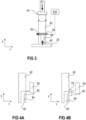
- Figure 3 schematically illustrates an embodiment wherein the channel 44 comprises (exactly) three openings 45.
- the suction device 410 may comprise a vacuum pump, whereas the suction device 410 in the embodiment of Figure 3 may instead comprise a compressed air supply. The different embodiments will be described in more detail further below.
- the first joining tool 40 may be configured to pick up a second joining partner 20 by sucking it towards a second one of the at least two openings 45, to place the second joining partner 20 on a first joining partner 10 arranged on the first support surface 401 of a second joining tool 41, and to perform an ultrasonic joining operation by vibrating/oscillating the sonotrode 42 to connect the second joining partner 20 to the first joining partner 10. That is, the first joining tool 40 combines the functions of a positioning tool and the functions of a joining tool in a single arrangement.
- the second joining partner 20 that is to be connected to the first joining partner 10 is sucked towards the tip of the sonotrode 42, wherein the tip of the sonotrode 42 is an end of the sonotrode 42 that, during a joining operation, faces towards and contacts the stack formed by the second joining partner 20 and the first joining partner 10 (and any additional joining partners included in the stack).
- the second one of the at least two openings 45 may be arranged at the tip of the sonotrode 42, as is schematically illustrated in Figures 2A, 2B and 3 .
- the first one of the at least two openings 45 to which the suction device 410 is connected may be arranged at any suitable position along the sonotrode 42.
- the channel 44 may comprise a first section extending through the sonotrode 42 in a vertical direction y (e.g., along the length of the sonotrode 42 between the tip and a second end of the sonotrode 42 opposite the tip).
- the channel 44 may further comprise a second section extending through the sonotrode 42 in a horizontal direction x.
- the first section and the second section of the channel 44 are arranged perpendicular to each other. This, however, is only an example.
- the second section for example, does not necessarily have to extend along a horizontal plane that is parallel to the support surface 401 of the second joining tool 41 when the sonotrode 42 presses the second joining partner 20 on the first joining partner 10.
- the second section instead may also extend diagonally from the first section towards the outside of the sonotrode 42, for example.
- the channel 44 generally may have any suitable form, length and cross-section.
- the channel 44 only comprises a single section extending vertically through the sonotrode 42 from the tip of the sonotrode 42 along the entire length of the sonotrode 42 to the second end of the sonotrode 42 opposite the tip.
- the vacuum pump may suck air through the channel 44 from the second opening 45 towards the first opening 45. This is schematically illustrated by means of arrows in Figures 2A and 2B .
- a vacuum pump may be coupled to the respective opening 45 of the channel 44 by means of a vacuum connector 50, for example, as is schematically illustrated in Figures 4A, 4B , 4C and 4D .
- a vacuum connector 50 is pressed against and directly adjoins the sonotrode 42.
- the vacuum connector 50 may be pressed against a section of the sonotrode 42 in which the first opening 45 of the channel 44 is formed.
- the vacuum pump (not specifically illustrated in Figure 4A ) is able to suck air through the channel 44 and through the vacuum connector 50 in order to suck the second joining partner 20 towards the sonotrode 42.
- the vacuum connector 50 may have a channel formed therein (not specifically illustrated), which forms a continuous channel together with the channel 44 through the sonotrode 42. As has been described above, the sonotrode 42 vibrates/oscillates while a joining operation is being performed. Further, vacuum connectors 50 are usually comparably stiff elements formed from a comparably hard material. The vacuum connector 50, when being pressed directly against the sonotrode 42 may not be able to deform and/or follow the movements of the sonotrode 42 during the joining operations.
- the vacuum connector 50 may be coupled to the sonotrode 42 by means of a flexible adapter element 52.
- a flexible adapter element 52 is very schematically illustrated in Figure 4B .
- the flexible adapter element 52 may be implemented in any suitable way in order to be able to deform while the sonotrode 42 vibrates during a joining operation.
- the vacuum connector 50 may remain essentially static even when the sonotrode 42 vibrates/oscillates.
- the flexible adapter 52 may be compressed / uncompressed when the sonotrode 42 vibrates/oscillates, thereby essentially preventing the vibrations/oscillations of the sonotrode 42 to be transferred to the vacuum connector 50.
- the flexible adapter element 52 is or comprises a bag bellow 54 (often also referred to as gaiter or boot).
- Bag bellows are elastic, pleated tubes that may be folded/unfolded in an accordion-like way. Bag bellows may be formed of plastic materials, for example. Any other materials, however, are generally also possible.
- the flexible adapter element 52 instead of as a bag bellow 54, may also be implemented in any other suitable way in order to be able to seal a passage between the channel 44 and the vacuum connector 50 while preventing the vibrations of the sonotrode 42 from being fully transmitted to the vacuum connector 50.
- the vacuum connector 50 may not be coupled to the sonotrode 42 at all.
- a connection between the vacuum connector 50 and the sonotrode 42 may be implemented by means of a so-called gap seal, or gap-type seal. This is schematically illustrated in Figure 4D .
- the vacuum connector 50 is arranged at a first distance d1 from the sonotrode 42.
- the first distance d1 may be constant when the sonotrode 42 does not vibrate, and may vary when the sonotrode 42 oscillates.
- the first distance d1 between the vacuum connector 50 and the sonotrode 42 in its resting position (no oscillation performed) may be larger than a maximum deviation of the sonotrode 42 from its resting position when it oscillates.
- the first distance d1 is comparably small such that an amount of air leaking through a gap 56 between the vacuum connector 50 and the sonotrode 42 is negligible.
- the first distance d1 when the sonotrode 42 is in its resting position, may be between 50 ⁇ m and 200 ⁇ m, or between 75 ⁇ m and 125 ⁇ m.
- a maximum ultrasonic amplitude of the sonotrode 42 may be 50 ⁇ m, for example. That is, even when the sonotrode 42 oscillates towards the vacuum connector 50, the first distance d1 is always greater than zero.
- the vacuum connector 50 is arranged in a direction x in which the sonotrode 42 oscillates. This, however, is only an example. It is also possible to arrange the vacuum connector 50 in a direction z perpendicular to the direction x in which the sonotrode 42 oscillates. That is, the sonotrode 42 may not oscillate towards the vacuum connector 50 and the first distance d1 between the vacuum connector 50 and the sonotrode 42 may remain essentially constant even when the sonotrode 42 oscillates. In this case, the constant first distance d1 may be between 10 ⁇ m and 100 ⁇ m, for example. That is, the first distance d1, even when the sonotrode 42 vibrates, is always greater than zero.
- the vacuum pump may be coupled to the respective opening 45 of the channel 44 by means of a flexible tube 60.
- a flexible tube 60 This is schematically illustrated in Figures 5A and 5B .
- the tube 60 may be directly coupled to the channel 44 by inserting one end of the tube 60 into the respective opening 45 of the channel 44.
- a second end of the tube 60 may be coupled to the vacuum pump.
- the tube 60 may unintentionally slip out of the channel 44. Therefore, in order to provide a more stable connection between the tube 60 and the channel 44, the tube 60 may be coupled to the channel 44 by means of an adapter element 62, as is schematically illustrated in Figure 5B .
- the tube 60 may be a silicone tube, for example.
- the adapter element 62 may be or comprise a screw-to-stub adapter, for example.
- a sonotrode 42 with a channel 44 extending from the tip all the way to an opposite end of the sonotrode 42 is schematically illustrated.
- the vacuum pump may be coupled to the channel 44 by means of a tube 60, for example.
- An adapter element 62 as has been described with respect to Figure 5B , is not specifically illustrated in Figure 6 , but, according to embodiments of the disclosure, may be used to form a connection between the tube 60 and the channel 44.
- the vacuum connector as has been described with respect to Figures 4A - 4C may also be used in connection with the arrangement illustrated in Figure 6 .
- the transducer 43 is coupled to a second end of the sonotrode 42 opposite the tip. This, however, is only an example.
- the transducer 43 generally may be coupled to the sonotrode 42 in any other position along the length of the sonotrode 42 between the tip and the second end of the sonotrode 42. This is schematically illustrated in Figure 7 .
- a channel 74 is provided in the transducer 43.
- the transducer 43 may comprise a stack of piezo-discs 70, for example.
- the stack of piezo-discs 70 may be coupled to the sonotrode 42, e.g., by means of a suitable connecting element 72, such that the channel 44 through the sonotrode 42 and the channel 74 through the connecting element 72 and the stack of piezo-discs 70 form a continuous channel.
- a vacuum pump may be coupled to the stack of piezo-discs 70 and may suck air through the continuous channel through the sonotrode 42, the connecting element 72, and the stack of piezo-discs 70.
- the connecting element 72 may be a passive element and may comprise or consist of steel, aluminum, tungsten carbide (WC), or any other suitable material.
- the channel 44 may comprise a second section, extending essentially vertically through part of the sonotrode 42, and a first section extending essentially horizontally through the sonotrode 42.
- the first section may extend from the first opening 45 to a third opening
- the second section may extend from the second opening 45 to the first section, thereby forming a T junction with the first section.
- the suction device 410 may comprise a compressed air supply configured to shoot compressed air through the first section of the channel 44 from the first opening 45 to the third opening, thereby sucking air into the second section of the channel 44 extending from the second opening 45 towards the first section (Venturi effect).
- the compressed air supply may be coupled to the channel 44 by means of a tube 60 and, optionally, an adapter element 62.
- a compressed air supply can also be coupled to the first opening 45 of the channel 44 in any other suitable way.
- a filter 90 may be arranged between the channel 44 and the suction device 410. This is schematically illustrated in Figure 9 . That is, a filter 90 may be arranged anywhere along, e.g., a tube 60 or a vacuum connector 50. In this way, air that is sucked through the tube 60 or vacuum connector 50 passes the filter 90 and particles or contaminations are filtered out of the air flow before the air flow reaches the suction device 410.
- the first joining tool 40 may be moved to the next second joining partner 20 that is to be connected to the first joining partner 10.
- the sonotrode 42 may be moved to pick up the next second joining partner 20, and may then move to the respective position on the first joining partner 10 in which the respective second joining partner 20 is to be mounted on the first joining partner 10. It, is, however, also possible that the first joining tool 40 remains static and instead the second joining tool 41, with the first joining partner 10 arranged thereon is repositioned after each joining operation.
- the sonotrode 42 may only be moved in a vertical direction y towards the first joining partner 10 in order to place the second joining partner 20 on and connect the second joining partner 20 to the first joining partner 10, and may be moved away from the first joining partner 10 in the vertical direction y after a joining operation has been completed.
- the first joining tool 40 and/or the second joining tool 41 may be movable vertically and/or horizontally. During the intermediate time intervals between two successive joining operations no pressing force is applied by the first joining tool 40.
- the first joining tool 40 may or may not vibrate/oscillate during the intermediate time intervals.
- the first joining tool 40 may not oscillate at least when picking up a second joining partner 20 and when positioning the second joining partner 20 on the first joining partner 10.
- the first joining tool 40 may be practically inactive (may not oscillate or vibrate) at least partly during the intermediate time intervals.
- "Practically inactive" in this context means that no joining operation is performed.
- the first joining tool 40 may still oscillate during sub-intervals of the intermediate time intervals, e.g., the first joining tool 40 may oscillate when moving away from the first joining partner 10 in order to clean the first joining tool 40. Due to the oscillations, any contaminants may be cast off from the first joining tool 40.
- the first opening 45 and the optional third opening 45 may generally be arranged at any position along the length of the sonotrode 42.
- the influence of the channel 44 on the mechanical properties of the sonotrode 42 may generally be neglected, especially if the channel 44 is arranged centrally in a vertical direction y of the sonotrode 42.
- the first opening 45 and the optional third opening 45 may reduce the mechanical stability of the sonotrode 42 to a certain degree.
- the openings 45 therefore, may constitute weak spots along the length of the sonotrode 42. There may be an increased risk of fractions forming in the sonotrode 42 in the areas around the openings 45.
- the openings 45 may be arranged in defined positions along the length of the sonotrode 42.
- a mode of vibration is schematically illustrated in dashed lines.
- the sonotrode 42 is generally vibrated/oscillated at a defined frequency. That is, the frequency is approximately the same for each of the different joining operations. This results in a constant mode of vibration.
- the frequency and, therefore, the positions of the vibration nodes K1, K2, K3, K4 are known for a specific sonotrode 42.
- the first opening 45, and the optional third opening 45 may be arranged along the length of the sonotrode 42 at a position of one of the plurality of vibration nodes K1, K2, K3, K4. In this way, the openings are arranged at positions of zero or almost zero deflection, and of zero or almost zero mechanical bending stress (no or only minimal bending of sonotrode 42 in areas of vibration nodes K1, K2, K3, K4). This may significantly reduce the risk of fractions forming in the sonotrode 42.
- a sonotrode 42 is only very schematically illustrated.
- the sonotrode 42 generally may have any suitable form, length and cross-section.
- the sonotrode 42 may be implemented as a simple pin or may have any other suitable more complex form or shape.
- the sonotrode 42 may comprise or consist of any suitable material, e.g., any suitable metallic, ceramic or partly ceramic material.
- a method for joining at least two joining partners 10, 20 by means of an ultrasonic joining arrangement comprises picking up a second joining partner 20 by sucking it towards the second one of the at least two openings 45, placing the second joining partner 20 on a first joining partner 10 arranged on a support surface 401 of a second joining tool 41, and performing an ultrasonic joining operation by vibrating the sonotrode 42 to connect the second joining partner 20 to the first joining partner 10.
Landscapes
- Engineering & Computer Science (AREA)
- Mechanical Engineering (AREA)
- Pressure Welding/Diffusion-Bonding (AREA)
Priority Applications (1)
| Application Number | Priority Date | Filing Date | Title |
|---|---|---|---|
| EP23192164.4A EP4509256A1 (fr) | 2023-08-18 | 2023-08-18 | Agencement et procédé d'assemblage par ultrasons |
Applications Claiming Priority (1)
| Application Number | Priority Date | Filing Date | Title |
|---|---|---|---|
| EP23192164.4A EP4509256A1 (fr) | 2023-08-18 | 2023-08-18 | Agencement et procédé d'assemblage par ultrasons |
Publications (1)
| Publication Number | Publication Date |
|---|---|
| EP4509256A1 true EP4509256A1 (fr) | 2025-02-19 |
Family
ID=87760406
Family Applications (1)
| Application Number | Title | Priority Date | Filing Date |
|---|---|---|---|
| EP23192164.4A Pending EP4509256A1 (fr) | 2023-08-18 | 2023-08-18 | Agencement et procédé d'assemblage par ultrasons |
Country Status (1)
| Country | Link |
|---|---|
| EP (1) | EP4509256A1 (fr) |
Citations (4)
| Publication number | Priority date | Publication date | Assignee | Title |
|---|---|---|---|---|
| US3464102A (en) * | 1967-03-10 | 1969-09-02 | Branson Instr | Solid acoustic horn with suction means |
| US5884831A (en) * | 1996-07-05 | 1999-03-23 | Ultex Corporation | Ultrasonic vibration bonding chip mounter |
| US6599381B2 (en) * | 2001-09-28 | 2003-07-29 | Hewlett-Packard Development Company, L.P. | Combination ultrasonic weld horn/vacuum |
| CN104136198A (zh) * | 2012-03-15 | 2014-11-05 | 耐克创新有限合伙公司 | 空心尖头焊接工具 |
-
2023
- 2023-08-18 EP EP23192164.4A patent/EP4509256A1/fr active Pending
Patent Citations (4)
| Publication number | Priority date | Publication date | Assignee | Title |
|---|---|---|---|---|
| US3464102A (en) * | 1967-03-10 | 1969-09-02 | Branson Instr | Solid acoustic horn with suction means |
| US5884831A (en) * | 1996-07-05 | 1999-03-23 | Ultex Corporation | Ultrasonic vibration bonding chip mounter |
| US6599381B2 (en) * | 2001-09-28 | 2003-07-29 | Hewlett-Packard Development Company, L.P. | Combination ultrasonic weld horn/vacuum |
| CN104136198A (zh) * | 2012-03-15 | 2014-11-05 | 耐克创新有限合伙公司 | 空心尖头焊接工具 |
Similar Documents
| Publication | Publication Date | Title |
|---|---|---|
| KR100324652B1 (ko) | 초음파 진동 접합 방법 | |
| US6811630B2 (en) | Ultrasonic vibration method and ultrasonic vibration apparatus | |
| CN101652845B (zh) | 电子元器件安装装置及电子元器件安装方法 | |
| TWI278052B (en) | Method of ultrasonic mounting and ultrasonic mounting apparatus using the same | |
| TW201831252A (zh) | 包括調諧型諧振器的超音波換能器系統、包括該系統的設備及提供該系統的方法 | |
| KR20200001999A (ko) | 초음파 접합 헤드, 초음파 접합 장치 및 초음파 접합 방법 | |
| EP4509256A1 (fr) | Agencement et procédé d'assemblage par ultrasons | |
| US7772025B2 (en) | Electronic device and method of manufacturing the same | |
| JP3767812B2 (ja) | 電子部品製造装置および電子部品製造方法 | |
| JP5281498B2 (ja) | 加圧式超音波振動接合方法および加圧式超音波振動接合装置 | |
| JP5663764B2 (ja) | 接合装置 | |
| WO2005006548A1 (fr) | Dispositif piezo-electrique et procede de production de ce dernier | |
| CN112581863A (zh) | 超声结合装置 | |
| JP3487162B2 (ja) | ボンディングツールおよびボンディング装置 | |
| EP1512485A1 (fr) | Procédé et dispositif de montage de composant électronique par application de vibrations ultranorores dans plusieurs directions, et circuit électronique | |
| KR101308410B1 (ko) | 교체형 가압부재가 구비된 초음파접합장치 | |
| JP2003059972A (ja) | ボンディングヘッド及びこれを備えたボンディング装置 | |
| JP4305270B2 (ja) | 部品接合装置および部品接合ツールならびに部品接合方法 | |
| JP2002334907A (ja) | 超音波ボンディング方法およびそれの実施に用いる超音波ボンディング装置 | |
| JPH04263436A (ja) | ダイボンディング装置 | |
| JP2007201108A (ja) | 電子部品接合装置および電子部品接合方法 | |
| JP2003209142A (ja) | ボンディングヘッドおよび実装装置 | |
| KR101361059B1 (ko) | 가압면 정렬을 위한 탄성부재가 구비된 초음파 접합장치 | |
| JPH1074767A (ja) | 微細ボールバンプ形成方法及び装置 | |
| JP2006332080A (ja) | 超音波フリップチップ実装装置 |
Legal Events
| Date | Code | Title | Description |
|---|---|---|---|
| PUAI | Public reference made under article 153(3) epc to a published international application that has entered the european phase |
Free format text: ORIGINAL CODE: 0009012 |
|
| STAA | Information on the status of an ep patent application or granted ep patent |
Free format text: STATUS: REQUEST FOR EXAMINATION WAS MADE |
|
| 17P | Request for examination filed |
Effective date: 20240918 |
|
| AK | Designated contracting states |
Kind code of ref document: A1 Designated state(s): AL AT BE BG CH CY CZ DE DK EE ES FI FR GB GR HR HU IE IS IT LI LT LU LV MC ME MK MT NL NO PL PT RO RS SE SI SK SM TR |
|
| STAA | Information on the status of an ep patent application or granted ep patent |
Free format text: STATUS: EXAMINATION IS IN PROGRESS |
|
| 17Q | First examination report despatched |
Effective date: 20251203 |