EP4509264A1 - Plaque de support pour un outil électrique de polissage ou de ponçage à main, outil électrique de polissage ou de ponçage à main doté d'une telle plaque de support, et programme informatique correspondant - Google Patents
Plaque de support pour un outil électrique de polissage ou de ponçage à main, outil électrique de polissage ou de ponçage à main doté d'une telle plaque de support, et programme informatique correspondant Download PDFInfo
- Publication number
- EP4509264A1 EP4509264A1 EP23191771.7A EP23191771A EP4509264A1 EP 4509264 A1 EP4509264 A1 EP 4509264A1 EP 23191771 A EP23191771 A EP 23191771A EP 4509264 A1 EP4509264 A1 EP 4509264A1
- Authority
- EP
- European Patent Office
- Prior art keywords
- backing plate
- polishing
- power tool
- sanding
- sensor element
- Prior art date
- Legal status (The legal status is an assumption and is not a legal conclusion. Google has not performed a legal analysis and makes no representation as to the accuracy of the status listed.)
- Withdrawn
Links
Images


Classifications
-
- B—PERFORMING OPERATIONS; TRANSPORTING
- B24—GRINDING; POLISHING
- B24D—TOOLS FOR GRINDING, BUFFING OR SHARPENING
- B24D9/00—Wheels or drums supporting in exchangeable arrangement a layer of flexible abrasive material, e.g. sandpaper
- B24D9/08—Circular back-plates for carrying flexible material
-
- B—PERFORMING OPERATIONS; TRANSPORTING
- B24—GRINDING; POLISHING
- B24B—MACHINES, DEVICES, OR PROCESSES FOR GRINDING OR POLISHING; DRESSING OR CONDITIONING OF ABRADING SURFACES; FEEDING OF GRINDING, POLISHING, OR LAPPING AGENTS
- B24B49/00—Measuring or gauging equipment for controlling the feed movement of the grinding tool or work; Arrangements of indicating or measuring equipment, e.g. for indicating the start of the grinding operation
-
- B—PERFORMING OPERATIONS; TRANSPORTING
- B24—GRINDING; POLISHING
- B24B—MACHINES, DEVICES, OR PROCESSES FOR GRINDING OR POLISHING; DRESSING OR CONDITIONING OF ABRADING SURFACES; FEEDING OF GRINDING, POLISHING, OR LAPPING AGENTS
- B24B23/00—Portable grinding machines, e.g. hand-guided; Accessories therefor
- B24B23/02—Portable grinding machines, e.g. hand-guided; Accessories therefor with rotating grinding tools; Accessories therefor
-
- B—PERFORMING OPERATIONS; TRANSPORTING
- B24—GRINDING; POLISHING
- B24B—MACHINES, DEVICES, OR PROCESSES FOR GRINDING OR POLISHING; DRESSING OR CONDITIONING OF ABRADING SURFACES; FEEDING OF GRINDING, POLISHING, OR LAPPING AGENTS
- B24B23/00—Portable grinding machines, e.g. hand-guided; Accessories therefor
- B24B23/04—Portable grinding machines, e.g. hand-guided; Accessories therefor with oscillating grinding tools; Accessories therefor
Definitions
- the present invention refers to a backing plate configured for releasable attachment to and use with a hand-held polishing or sanding power tool.
- the backing plate has an essentially plate-shaped form and comprises a top surface having an attachment member adapted for releasable attachment to a driving shaft or to part of an eccentric element of the polishing or sanding power tool and a bottom surface adapted for releasable attachment of a polishing or sanding member thereto.
- the backing plate is at least partially made of a polyamide synthetic material.
- the invention refers to a hand-held polishing or sanding power tool comprising a tool housing, an electric or pneumatic motor located therein and a driving shaft driven by the electric or pneumatic motor and protruding from the tool housing.
- the power tool further comprises a backing plate having a bottom surface adapted for releasable attachment of a polishing or sanding member thereto.
- the backing plate is releasably attached to the driving shaft or to part of an eccentric element fixedly attached to the driving shaft.
- the invention refers to a computer program product configured to be executed on a processor of an electronic device, e.g., a mobile smartphone, a tablet computer, a laptop computer, a polishing or sanding power tool or the like, and further configured to make the electronic device perform specific steps when executed on the processor.
- a processor of an electronic device e.g., a mobile smartphone, a tablet computer, a laptop computer, a polishing or sanding power tool or the like
- Backing plates of the above-mentioned kind as well as hand-held polishing or sanding power tools with such backing plates attached thereto are well-known in the prior art.
- Various types of backing plates are manufactured and sold by RUPES S.p.A. from Vermezzo (MI), Italy (see: https://www.rupes.com/category-product/consumables/consumables-backing-pads/).
- backing plates are known to have a supporting structure made of a rigid material such as metal and/or a rigid plastic material and a damping layer made of a resilient synthetic material, e.g., urethan, in particular polyurethan, arranged between the supporting structure and the bottom surface of the backing plate adapted for releasable attachment of a polishing or sanding member thereto.
- the supporting structure commonly comprises an attachment member for releasable attachment of the backing plate to the distal end of a driving shaft or to part of an eccentric element of the polishing or sanding power tool, fixedly attached to the driving shaft.
- polishing and sanding power tools as well as polishing and sanding members (e.g., polishing pads, sanding paper or fabric) and polishing and sanding compounds (e.g., liquids or pastes), and to adapt them as well as possible to the surfaces of the workpiece to be worked on, in particular in terms of surface material as well as surface extension and dimensions.
- polishing and sanding members e.g., polishing pads, sanding paper or fabric
- polishing and sanding compounds e.g., liquids or pastes
- the backing plate comprises at least one sensor element adapted for measuring one or more quantities comprising ambient parameters of an environment surrounding the backing plate and/or operational parameters of the backing plate during intended use of the backing plate, and further adapted for outputting at least one sensor signal indicative of the one or more measured quantities.
- the invention suggests an intelligent backing plate with one or more integrated sensor elements.
- These integrated sensor elements have the advantage that during intended use of the backing plate they are positioned much closer to the region where some of the quantities to be measured occur.
- the sensor elements are located much closer to the actual working surface than external sensor devices commonly used in the past.
- the measured quantities can be measured much more accurately than with the external sensor devices in the prior art.
- the rotational speed of the backing plate about the rotational axis or an operational temperature of the backing plate during its intended use can be measured much more accurately with one or more internal sensor elements.
- the measured operational temperature of the backing plate may be indicative of and allow determination or estimation of a working temperature of the bottom polishing or sanding surface of a polishing or sanding member attached to the bottom surface of the backing plate.
- the working temperature of the working surface during intended use of the polishing or sanding power tool has a large impact on the outcome and quality of the sanding or polishing process.
- integrated sensor elements have the advantage that they can measure, process, record/store and output quantities which up to now could not be measured by the external sensor devices or only at a considerable cost and effort. For instance, a deformation of the backing plate or internal forces acting within the backing plate during its intended use can be measured much more easily with one or more internal sensor elements.
- sensor elements are usually manufactured in semiconductor technology and, therefore, are very small and light weight. This allows integration of one or more sensor elements into the backing plate without any recognisable negative impact on the usability of the backing plate and its characteristics during its intended use.
- the backing plate may have many different forms.
- the backing plate in a view from above onto the surface extension of the backing plate, the backing plate has a rectangular, square, triangular or delta-shaped form.
- the backing plate may have an axis extending essentially perpendicular in respect to the surface extension of the backing plate.
- the axis may extend through a geometric centre, a centre of mass or a centre of gravity of the backing plate.
- the backing plate has an essentially disc-shaped form with a circular circumference and a rotational axis extending through a centre of gravity of the backing plate.
- the at least one sensor element is adapted for measuring at least one of the following quantities:
- the ambient temperature is the temperature in an environment area surrounding the surface to be worked, the polishing or sanding power tool and the user operating the power tool.
- the sensor element could be embodied as a temperature sensor (e.g., a NTC or PTC thermistor).
- the respective sensor element is preferably located near a top or a lateral surface of the backing plate.
- the ambient humidity is the humidity or moisture in an environment area surrounding the surface to be worked, the polishing or sanding power tool and the user operating the power tool.
- the sensor element could be embodied as a humidity sensor (e.g., a hygrometer or capacitive humidity sensor).
- the respective sensor element is preferably located near a top or a lateral surface of the backing plate.
- the ambient air pressure is the air pressure in an environment area surrounding the surface to be worked, the polishing or sanding power tool and the user operating the power tool.
- the sensor element could be embodied as a pressure sensor (e.g., a barometric pressure sensor based on a piezoresistive or a capacitive or a piezoelectric effect).
- the respective sensor element is preferably located near a top or a lateral surface of the backing plate.
- An operational temperature of the backing plate during its intended use can be measured best if the respective sensor element is located near a bottom surface of the backing plate which is in contact with a polishing member attached thereto.
- the operating temperature on the working surface is important in order to avoid its overheating due to friction and possibly even a damage of the working surface during sanding and polishing operations.
- Sanding members commonly used for sanding operations such as a sanding paper or a sanding fabric are usually rather thin, so that the operational temperature of the working surface is present almost identically in the sanding paper or fabric and at or near the bottom surface of the backing plate, where it can be measured by the internal sensor element.
- the sensor element could be embodied as a temperature sensor (e.g., a NTC or PTC thermistor).
- a temperature of a bottom surface of a polishing member which is in contact with the working surface during intended use of the power tool, can be measured by the sensor element of the backing plate.
- An overheating of the bottom surface of a polishing member should be avoided, in particular in polishing members comprising an open cell foam structure. Otherwise, overheating of the bottom surface of the polishing member may lead to cells melting, closing and/or collapsing and to a damage of the polishing pad, in particular of its bottom surface, and to scratches on the working surface.
- the temperature of a bottom surface of a polishing member in particular of a polishing member having an open cell foam structure, and or the temperature of the working surface, could be measured by one or more infrared thermometers located in the backing plate and emitting IR-rays towards the working surface.
- the rotational speed of the backing plate could be reduced, an alarm (acoustic or visual) could be emitted to the user and/or the user could press the power tool onto the working surface in an axial direction extending parallel to the rotational axis of the backing plate with less pressure.
- An operational rotational speed of the backing plate during its intended use can be measured best if the respective sensor element is located eccentrically, i.e., in a distance to the rotational axis of the backing plate.
- the sensor element could be embodied as an acceleration sensor or as a speed sensor, e.g., a hall sensor or a photoelectric sensor, the latter two requiring a respective element located in a corresponding position in the tool housing and emitting a signal (e.g., a light or a magnetic field) which is then detected by the sensor element, i.e., each time the sensor element passes over the respective element.
- a signal e.g., a light or a magnetic field
- An operational time during which the backing plate is in its intended use can be measured best by means of a timer which is started once the start of an intended use of the backing plate has been detected, possibly by another sensor element, and stopped when an end of the intended use of the backing plate has been detected, again possibly by another sensor element.
- the other sensor element could be, for instance, an acceleration sensor or a speed sensor.
- the measured operational times of the backing plate may refer to each operation cycle (from start to subsequent stop of the backing plate) or they may be accumulated over time in order to obtain the overall operational time of the backing plate. If the overall operational time of a backing plate exceeds a given threshold value, the backing plate could be replaced as a precautionary measure, before it is actually damaged.
- a deformation of the backing plate during its intended use may comprise an increase of its diameter due to centrifugal force acting on the backing plate, a reduction of its height due to the centrifugal force, a distortion or a wave formation (so-called warping effect), especially at the outer edge of the backing plate, due to high rotational speeds of the backing plate, just to name a few.
- a deformation of the backing plate can be measured best with sensor elements in the form of a strain gauge or a Wheatstone bridge.
- one or more of these sensor elements are placed in the backing plate where the deformations typically occur.
- One or more respective sensor elements could also be used to measure one or more internal forces acting within the backing plate during its intended use.
- a pressure with which the user presses the backing plate with the sanding or polishing member attached thereto onto the working surface can be measured best with a pressure sensor. If the backing plate with a polishing member comprising an open cell foam structure attached thereto is pressed with too much pressure onto the working surface, this may result in the polishing pad being used similar to a damper, where the bottom surface is practically stuck to the working surface and only the top surface of the polishing pad follows the working movement performed by the backing plate. This may lead to an inefficient polishing work and to the polishing pad being vigorously worked through, which may lead to a premature material damage.
- the rotational speed of the backing plate could be reduced, an alarm (acoustic or visual) could be emitted to the user and/or the user could reduce the pressure with which he presses the power tool onto the working surface in an axial direction extending parallel to the rotational axis of the backing plate.
- Vibrations of the backing plate can be measured best by means of an acceleration sensor.
- the acceleration sensor may measure accelerations in one direction, in two directions perpendicular to each other or in three directions perpendicular to each other.
- the vibrations of the backing plate may be indicative of vibrations of the entire power tool and/or of the tool housing held by a user of the power tool.
- the rotational speed of the backing plate could be reduced or shifted to a speed which has less vibrations, an alarm (acoustic or visual) could be emitted to the user and/or the user could change the pressure with which he presses the power tool onto the working surface in an axial direction extending parallel to the rotational axis of the backing plate.
- the backing plate comprises an electric energy storage device adapted for storing electric energy and/or an electric energy generation device adapted for generating electric energy during intended use of the backing plate, and wherein the energy storage device or the energy generation device is connected to the at least one sensor element and possibly other electric or electronic components of the backing plate in order to provide them with electric energy for their operation.
- the electric energy storage device may comprise one or more batteries, capacitors or the like.
- the energy storage device comprises one or more so-called button cells or coin batteries.
- the electric energy storage device could be designed such that it stores enough electric energy necessary for operating the electric and electronic components contained in the backing plate during the expected lifetime.
- the energy storage device could also be realized rechargeable or exchangeable. Charging of the energy storage device may be effected inductively, conductively or by means of a charging cable connected to a respective charging port which may be located on an external surface of the backing plate. For exchanging the energy storage device and replacing it by a new or full one, the energy storage device could be located in a compartment accessible from outside the backing plate.
- the electric energy generation device could be configured to generate the electric energy inductively (through (electro-) magnetic induction, similar to a dynamo) or through a piezoelectric effect.
- Inductive generation of electric energy within the backing plate could be realized as follows:
- the backing plate comprises a coil of conductive wire.
- One or more permanent magnets are located in the tool housing near and facing the backing plate attached to the driving shaft or to part of an eccentric element. The permanent magnets create at least one magnetic field. During operation of the polishing or sanding power tool the backing plate rotates in respect to the tool housing.
- the wire coil rotates in the at least one magnetic field, thereby generating an electric current in the wire coil, which can be harvested, i.e., used by the electric or electronic components of the backing plate and/or stored in an electric energy storage device.
- the energy generation device may be connected to the at least one sensor element either directly or indirectly through one or more other electric or electronic components, such as through the energy storage device.
- a piezoelectric element is located inside the backing plate. The piezoelectric element transforms its mechanical deformation due to a centrifugal force during rotation of the backing plate into electric energy which can be harvested.
- the backing plate comprises a processing module adapted for processing the one or more sensor signals.
- the processing module preferably comprises a microprocessor or a microcontroller adapted for executing a computer program configured to realize the processing module's function when executed on the microprocessor or the microcontroller.
- the processing module or the computer program executed thereon, respectively, is configured to receive the one or more sensor signals form the at least one sensor element and to process the received sensor signals.
- Processing of the sensor signals may comprise extracting the information contained in the sensor signals, i.e., the one or more quantities measured by the at least one sensor element.
- Processing may further comprise the generation of one or more respective electric signals depending on the information contained in the sensor signals.
- Such components may comprise a storage device for storing the one or more quantities measured by the at least one sensor element, a visual output device, a wireless communication device, or the like, which are described in further detail hereinafter.
- the processing module could comprise a logic for combining and/or linking two or more of the measured quantities, in particular different types of measured quantities. This could be useful in order to gain information about the backing plate and/or other parts of the power tool beyond the information content of the individual measured quantities.
- vibrations (cinematic energy) are caused by a rotating unbalance or an uneven distribution of mass around an axis of rotation.
- the magnitude of vibrations is directly proportional to the unbalanced mass
- the frequency of vibrations is directly proportional to the speed of rotation around the axis of rotation.
- the logic may be adapted to calculate an optimal working point of the power tool in terms of rotational speed of the backing plate, pressure with which the backing plate or the polishing or sanding member is pressed onto the working surface, equilibration of the backing plate with the polishing or sanding member attached thereto, temperature of the working surface and/or of the bottom surface of the sanding or polishing member during intended use, vibrations, etc. For instance, a smaller orbit of the backing plate may favour a higher rotational speed of the backing plate, whereas a larger orbit may favour a lower rotational speed.
- the idea is to find an optimal working point and to operate the power tool in that working point in order to work with an optimal efficiency and/or with reduced temperatures and vibrations.
- the backing plate comprises a visual output device for outputting visual information indicative of the one or more quantities measured by the at least one sensor element.
- the visual output device is at least partially located in an external surface of the backing plate, in particular in the top surface of the backing plate, in order to allow a user during intended use of the power tool and the backing plate to visually capture the visual information outputted by the visual output device.
- the visual output device is preferably located inside the backing plate in such a manner that the visual information indicative of the one or more quantities measured by the at least one sensor element can be output to the environment surrounding the backing plate and can be visually perceived by the user from outside the backing plate.
- a printed circuit board for instance a processor, a co-processor, electric wires, a light generation or backing lighting unit of the visual output device or the like, may be located inside the backing plate.
- the visual output device may comprise at least one light spot, in particular one or more LEDs, a light guide, an electroluminescent (EL) wire or a display device, in particular a screen.
- the light spots may be configured to emit light of different colours.
- the light spots may output different information content, i.e., different values for the one or more quantities measured by the at least one sensor element, by emitting light of a certain colour and/or by emitting light continuously or intermittently.
- a light guide may be arranged extending along a top surface or a lateral surface of the backing plate. Light of one or more given colours is coupled into an end of the light guide and coupled out of the light guide along its extension by means of de-coupling elements.
- the light guide may output different information content, i.e., different values for the one or more quantities measured by the at least one sensor element, by emitting light of a certain colour and/or by emitting light continuously or intermittently.
- An EL wire may be arranged extending along a top surface or a lateral surface of the backing plate. When applying electric current to the EL wire it will emit light of a given colour and intensity.
- the EL wire may output different information content, i.e., different values for the one or more quantities measured by the at least one sensor element, by emitting light at a given intensity and/or by emitting light continuously or intermittently.
- LCD screens work by utilizing liquid crystals that manipulate light to produce images.
- LCD screens can be further categorized based on their backlighting technology, such as LED (Light Emitting Diode) LCD or OLED (Organic Light Emitting Diode) LCD.
- Organic Light Emitting Diode (OLED) screens are known for their vibrant colours and high contrast levels. Each pixel in an OLED screen emits light independently, allowing for true black levels and improved energy efficiency.
- E-paper also known as electronic paper or electronic ink, is a type of display technology that mimics the appearance of ink on paper. They offer high readability even in direct sunlight and consume very little power.
- AMOLED screens are a variation of OLED technology. They use a thin-film transistor (TFT) array to control the flow of current to individual pixels. AMOLED screens are known for their deep blacks, high contrast, and fast response times.
- TFT thin-film transistor
- the visual output device could be configured to output the visual information in the form of a holographic projection creating virtual moving objects, letters or numbers in an area fully visible by the user during intended use of the backing plate.
- the backing plate comprises a wireless communication device for wirelessly transmitting electromagnetic signals containing information indicative of the one or more quantities measured by the at least one sensor element.
- the wirelessly transmitted electromagnetic signals may be received by a respective wireless communication device of an electronic device, i.e., a mobile smartphone, a tablet computer, a laptop computer, the polishing or sanding power tool to which the backing plate is attached, or the like.
- the electromagnetic signals received by the electronic device i.e., the mobile smartphone, tablet computer, laptop computer, the power tool or the like, may be processed by a processor of the electronic device.
- the processing of the electromagnetic signals comprises extracting the information contained therein, i.e., the one or more quantities measured by the at least one sensor element.
- numbers or graphics indicative of the information contained in the received electromagnetic signals may be outputted on a high-resolution screen of the electronic device.
- This embodiment allows a convenient outputting of the current values of the one or more quantities measured by the at least one sensor element to a user during operation of the polishing or sanding power tool and intended use of the backing plate.
- the user may constantly monitor the current values of the one or more quantities measured by the at least one sensor element of the backing plate during operation of the power tool.
- the wirelessly transmitted electromagnetic signals may be received by the polishing or sanding power tool to which the backing plate is attached.
- the power tool comprises a respective wireless communication device adapted for receiving the wirelessly transmitted electromagnetic signals containing information indicative of the one or more quantities measured by at least one sensor element of the backing plate and for generating electric signals corresponding to the received electromagnetic signals.
- the polishing or sanding power tool comprises an ECU adapted for controlling operation of the electric or pneumatic motor, wherein the ECU is configured to receive the electric signals generated by the wireless communication device and to generate and output respective control signals for controlling operation of the electric or pneumatic motor, depending on the one or more quantities measured by at least one sensor element of the backing plate.
- This embodiment allows a control of the power tool operation depending on the current operational status of the backing plate, measured by the at least one sensor element of the backing plate. This has the advantage that the polishing or sanding operation can be optimized in-situ and online, i.e., during operation of the power tool and intended use of the backing plate.
- the wirelessly electromagnetic signals transmitted by the wireless communication device of the backing plate could also contain information relating to a unique identifier of the backing plate.
- the identifier could be unique for each and every backing plate or only for certain types of backing plates, i.e., having certain diameters, made of certain materials, adapted for use in certain working movements (e.g., rotary, random-orbital, eccentric, gear-driven). In the latter case, all backing plates of the same type could have the same identifier.
- the unique identifier could be received by a respective wireless communication device making part of the power tool, to which the backing plate is attached. Operation of the power tool could be interrupted or prevented if the unique identifier does not correspond to a given identifier. By doing so, user safety can be increased because operation of the power tool with a wrong type of backing plate is avoided. Furthermore, it would be possible to make sure that the power tool is used only together with backing plates of a given quality and/or made by a certain manufacturer.
- the at least one internal sensor element and possibly other electric or electronic components integrated in the backing plate are preferably arranged on a printed circuit board (PCB) and electrically contacted through conductive paths and pads provided on the PCB.
- the PCB may be a rigid or a flexible board.
- Flexible PCBs also known as flex circuits or flex boards, are made of a combination of different materials that provide flexibility and electrical conductivity.
- the primary materials used in the construction of flexible PCBs include:
- a substrate which is the base material of the flexible PCB and provides mechanical support and flexibility.
- Common substrate materials used in flexible PCBs include polyimide (PI) and polyester (PET).
- Polyimide is the most widely used material due to its excellent thermal stability, flexibility, and high-temperature resistance.
- a copper foil which is typically very thin, usually in the range of 9 to 70 micrometers, to maintain flexibility. Copper is the primary conductive material used in flexible PCBs. It is laminated onto the substrate and acts as the conductive traces, pads, and other conductive elements. Adhesive layers are used to bond the copper foil to the substrate and provide mechanical stability to the flexible PCB. They also act as insulating layers between the conductive traces and the substrate.
- Coverlay also known as cover film or cover coat, is a protective layer applied on top of the flexible PCB. It provides insulation, protection against environmental factors such as moisture and dust, and enhances the mechanical strength of the circuit.
- a solder mask which is a layer of polymer resin applied over the copper traces to protect them from oxidation, solder bridging during assembly, and other potential issues. These materials are combined and laminated together using heat, pressure, and adhesive processes to create the flexible PCB.
- the PCB may be arranged inside the backing plate during manufacturing of the backing plate and may extend over the entire circumferential extension of the backing plate or over only part thereof.
- Other electric or electronic components integrated in the backing plate, which are not arranged on a PCB are possibly connected to the PCB by electric wires, in particular by bonding wires.
- the PCB allows easy and fast arrangement and electric contacting of the at least one sensor element and possibly other electric or electronic components within the backing plate.
- the entire electronic circuit comprising the PCB and the at least one sensor element and possibly other electric or electronic components to be arranged inside the backing plate during or after manufacturing of the backing plate can be inserted therein as a single unit in a single mounting process.
- the PCB can be manufactured, fitted and contacted with the electric or electronic components, remote from the place of manufacture of the backing plate.
- the PCB is manufactured and assembled in a cleanroom, particularly preferably in an ultra-clean environment. Mounting of the entire assembled PCB-unit, i.e., its insertion into the backing plate, can be performed in a regular manufacturing environment for backing plates. No cleanroom or even an ultra-clean environment is necessary.
- the PCB may be inserted into the backing plate concentrically in respect to the rotational axis of the backing plate.
- the electric or electronic components are mounted on the PCB such that their individual weights are evenly distributed in the circumferential direction, a well-balanced intelligent backing plate can be easily created. It is advisable to accurately balance the at least one sensor element and possibly other electric or electronic components integrated into the backing plate in respect to the rotational axis of the backing plate in order to avoid an imbalance and resulting vibrations during the rotation of the backing plate about its rotational axis.
- the backing plate is at least partially made of a rigid plastic material, for instance a polyamide synthetic material.
- the characteristics of the rigid plastic material may be optimized by selectively adding carbon or glass fibres, but also mineral or PTFE filled additives to the plastic material.
- the backing plate according to the invention preferably does not have a damping layer made of a resilient synthetic material, such as urethane, in particular polyurethan.
- the at least one sensor element and possibly other electric or electronic components are preferably arranged in the rigid plastic material which the backing plate is made of.
- the backing plate may have an insert, preferably made of a rigid plastic material and/or a metal.
- the insert may comprise the attachment member for releasable attachment of the backing plate to a distal end of the driving shaft or to part of an eccentric element of the polishing or sanding power tool.
- the insert may be formed by the rigid plastic material or fixedly attached thereto, e.g., by gluing, welding or co-moulding.
- the backing plate may be made entirely of the rigid plastic material, for instance a polyamide synthetic material, into which the attachment member on the top surface and possibly also an insert may be co-moulded.
- the layer of hook or loops may be attached to the bottom surface of the rigid plastic material by gluing, welding or also co-moulding.
- a damping layer made of a resilient material e.g., of an urethane material, in particular a polyurethane material, is provide between the rigid plastic material and the bottom layer of hooks or loops.
- the layer of hooks or loops would be attached to a bottom surface of the resilient material.
- at least some of the electric or electronic components could also be provided in the resilient material of the damping layer.
- the backing plate may be provided with channels, holes and/or recesses in order to enable an air flow from the working surface through the backing plate and further into a dust extraction system.
- the air flow may be used to remove dust and small particles from the working surface, especially during a sanding operation, and/or for cooling components of the power tool.
- the air flow through the channels, holes and/or recesses provided in the backing plate may also be used to cool the electric or electronic components integrated into the backing plate.
- a temperature sensor element is preferably located in a distance to the channels, holes and/or recesses.
- a layer of hooks or loops of a hook and loop fastener system may be attached to a bottom surface of the backing plate.
- the layer of hooks or loops is attached directly to the rigid plastic material.
- the layer of hooks or loops is adapted to interact with a corresponding layer of loops or hooks provided on a top surface of a polishing or sanding member, thereby allowing releasable attachment of the polishing or sanding member to the bottom surface backing plate.
- the layer of hooks or loops comprises a carrier material web to which the hooks or loops are fixedly attached.
- the bottom surface of the backing plate has a recessed region which is limited in a radial direction by an outer circumferentially extending rim section.
- the recessed region is preferably made in the bottom surface of the rigid plastic material.
- the carrier material web of the layer of hooks or loops is preferably attached to the bottom surface of the backing plate in the recessed region so that only the hooks or loops extend beyond the circumferential rim section.
- the layer of hooks or loops is preferably fixedly attached to the bottom surface of the backing plate, for instance by gluing, welding or (co-) moulding.
- a flat disc- or ring-shaped plate may be attached to the top surface of the backing plate, thereby possibly covering channels, holes and/or recesses opening into or running along the top surface of the backing plate.
- the flat plate preferably has a ring shape with a central hole for receiving the attachment member.
- the flat plate is preferably attached to the top surface of the backing plate by means of gluing, welding or through a mechanical snap-in connection.
- the entire backing plate may be manufactured in a co-moulding process, where a support structure of metal or the attachment member, the disc shaped plate and/or the layer of hooks and loops are positioned in a mould into which the heated rigid plastic material, in particular the polyamide synthetic material, is then inserted.
- a support structure of metal or the attachment member, the disc shaped plate and/or the layer of hooks and loops are positioned in a mould into which the heated rigid plastic material, in particular the polyamide synthetic material, is then inserted.
- One or more of the support structure made of metal, the attachment member, the disc shaped plate and the layer of hooks and loops may be positioned in the mould after the insertion of the heated rigid plastic material. Thereafter, the mould is preferably closed by means of a lid and the rigid plastic material is cured, possibly under a pressure higher than the ambient pressure and/or a temperature higher than the ambient temperature.
- the at least one sensor element and possibly other electric or electronic components are preferably located inside the backing plate not visible from outside the backing plate.
- the sensor element and possibly other electric or electronic components are located inside the rigid plastic material, e.g., the polyamide material, of the backing plate.
- the rigid plastic material e.g., the polyamide material
- hollow cavities or recesses are defined in the backing plate during its manufacturing, into which the at least one sensor element and possibly other electric or electronic components can then be inserted.
- the sensor element and possibly other electric or electronic components can withstand respective temperatures and/or the rigid plastic material is not heated to too high a temperature during a moulding process, to introduce the at least one sensor element and possibly other electric or electronic components into the rigid plastic material during a co-moulding process.
- At least part of the one or more receiving cavities are filled with an insulating material.
- the insulating material may be an epoxy or silicone resin, polyurethane, so-called glob top materials or the like.
- the attachment member may comprise a central recess member having a circumferential form which is not rotationally symmetric in respect to the rotational axis of the backing plate.
- the recess member is adapted to receive a corresponding protrusion member attached to or forming a distal end of the driving shaft of the power tool or attached to part of an eccentric element.
- the driving shaft may be driven by an electric or pneumatic motor of the power tool and preferably protrudes from a tool housing. After attachment of the backing plate to the driving shaft, a rotational axis of the driving shaft and the rotational axis of the backing plate are congruent.
- the eccentric element is attached with a first side, e.g., the top side, to a distal end of the driving shaft in a torque proof manner, in order to transmit torque from the driving shaft to the eccentric element.
- a mallet pin is held in the rest of the eccentric element in a manner freely rotatable about the mallet pin's longitudinal axis.
- the mallet pin's longitudinal axis extends in a distance and parallel to the rotational axis of the driving shaft.
- the backing plate is attached to the distal end of the mallet pin, the mallet pin's longitudinal axis and the rotational axis of the backing plate are congruent.
- a protrusion member is attached to a distal end of the mallet pin facing away from the rest of the eccentric element. The protrusion member is received by the corresponding recess of the attachment member of the backing plate.
- the attachment member may comprise a central pin, in particular a threaded pin, adapted to be receive in a hole, in particular a threaded bore, provided in a distal end of the driving shaft of the power tool or in part of an eccentric element, in particular in a distal end of a mallet pin of the eccentric element.
- Direct attachment of the backing plate to the driving shaft will result in a rotational working movement of the backing plate during operation of the power tool and intended use of the backing plate.
- Indirect attachment of the backing plate to the driving shaft by means of an eccentric element will result in a random-orbital working movement of the backing plate. In the latter case, if free rotation of the backing plate in respect to the tool housing is prevented or limited, the backing plate will perform an eccentric movement.
- the backing plate is indirectly attached to the driving shaft by means of a gear arrangement, in particular a planetary gear arrangement, making part of the power tool, the backing plate will perform a gear-driven working movement.
- the gear arrangement defines an exact number of rotations of the backing plate about its rotational axis depending on the number of rotations of the driving shaft about its respective rotational axis. With other words, the gear arrangement defines a given ratio between the rotation speeds of the driving shaft about its rotational axis and the backing plate about its rotational axis.
- the present invention suggests an intelligent backing plate for use with polishing or sanding power tools, which allows a further optimization of the polishing or sanding process, leading to higher quality results of the polishing or sanding process.
- the object of the present invention is also solved by a polishing or sanding power tool comprising the features and characteristics of claim 14.
- the polishing or sanding power tool comprises an intelligent backing plate of the type described above.
- the object of the present invention is also solved by a computer program product comprising the features and characteristics of claim 17.
- the computer program product is configured to be executed on a processor of an electronic device, e.g., a mobile smartphone, a tablet computer, a laptop computer, a polishing or sanding power tool or the like, the computer program product further configured to realize the following steps when executed on the processor:
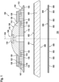
- Fig. 1 shows schematically an example of a backing plate 100 known from the prior art in a cross-sectional view.
- the backing plates 10 according to the present invention may have at least some and possibly all of the features and characteristics of the known backing plate 100 described hereinafter.
- the backing plate 100 is configured for use with a hand-held polishing or sanding power tool 200 (see Fig. 10 ).
- the backing plate 100 shown in these examples has an essentially disc-shaped form with a circular circumference 102 and a rotational axis 104 extending through a centre of the backing plate 100.
- the backing plate 100 further comprises a top surface 106 having an attachment member 108 adapted for releasable attachment to a driving shaft 202 or to a part 204 of an eccentric element 206 of the polishing or sanding power tool 200 (see Fig. 10 ) and a bottom surface 110 adapted for releasable attachment of a polishing member 400 or a sanding member 500 thereto.
- the backing plate 100 may have a supporting structure 114 made of a rigid plastic material such as polyamide, for flexural rigidity of the backing plate 100.
- a damping layer 112 made of a resilient material such as urethan, in particular polyurethan, may be located between the supporting structure 114 and the bottom surface 110 of the backing plate 100.
- the backing plate 100 may have an insert 116, preferably made of a rigid plastic material or a metal.
- the insert 116 may comprise the attachment member 108 for releasable attachment of the backing plate 100 to the driving shaft 202 or to the part 204 of the eccentric element 206 of the polishing or sanding power tool 200.
- the backing plate 100 in particular the damping layer 112, may be provided with channels 118, holes 120 and/or recesses 122 in order to enable an air flow from a working surface 124 through respective openings or holes 502 provided in a sanding member 500 attachable to the bottom surface 110 of the backing plate 100.
- the openings 502 of the sanding member 500 are aligned with the holes 120 and/or recesses 122 of the backing plate 100.
- the air flow further flows through the channels 118, holes 120 and/or recesses 122 of the backing plate 100 and finally into a dust extraction system (not shown).
- the air flow may be used to remove dust and small particles from the working surface 124, especially during a sanding operation, and/or for cooling components, especially electric or electronic components, of the power tool 200.
- a layer 126 of hooks or loops of a hook and loop fastener system may be attached to a bottom side of the damping layer 112, forming the bottom surface 110 of the backing plate 100.
- the layer 126 of hooks or loops is adapted to interact with a corresponding layer 402; 504 of loops or hooks provided on a top surface 404; 506 of the polishing member 400 or the sanding member 500, thereby allowing releasable attachment of the polishing or sanding member 400; 500 to the backing plate 100.
- a flat disc shaped plate 128 may be attached to a top side of the supporting structure 114 and/or the damping layer 112, forming or making part of the top surface 106 of the backing plate 100, possibly covering channels 118, holes 120 and/or recesses 122 opening into or running along the top side of the supporting structure 114 and/or the damping layer 112.
- the disc shaped plate 128 preferably has a ring shape with a central hole 130 for the attachment member 108 (or the driving shaft 202 or the attachment part 204 of the eccentric element 206 of the power tool 200) to pass through.
- the disc shaped plate 128 may be made of a rigid plastic material.
- the disc shaped plate 128 and/or the layer 126 of hooks or loops may be attached to the supporting structure 114 and/or the damping layer 112 by gluing, welding or during a co-moulding process.
- the entire known backing plate 100 may be manufactured in a co-moulding process, where the support structure 114, the metal insert 116 or the attachment member 108, the disc shaped plate 128 and/or the layer 126 of hooks and loops are positioned in a mould into which the heated urethan material is introduced.
- One or more of the support structure 114, the metal insert 116, the attachment member 108, the disc shaped plate 128 and the layer 126 of hooks and loops may be positioned in the mould after the insertion of the heated urethan material. Thereafter, the mould is preferably closed by means of a lid and the urethan material is cured, possibly under a pressure higher than the ambient pressure and/or a temperature higher than the ambient temperature.
- the above-described features and characteristics of the known backing plate 100 shown in Fig. 1 may also each be present in a backing plate 600 according to the present invention, each feature and characteristic either alone or in any combination with other features and characteristics mentioned above or hereinafter.
- Features and characteristics also present in the backing plate 600 according to the invention have been assigned the same reference signs as in the known backing plate 100.
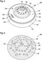
- the backing plate 600 may have many different forms. For instance, in a view from above onto a surface extension of the backing plate 600, the backing plate 600 may have a rectangular, square, triangular or delta-shaped form.
- the backing plate 600 may have an axis extending essentially perpendicular in respect to its surface extension. The axis may extend through a geometric centre, a centre of mass or a centre of gravity of the backing plate 600. According to a preferred embodiment of the invention, shown in the accompanying drawings, it is suggested that the backing plate 600 has an essentially disc-shaped form with a circular circumference 102 and a rotational axis 104 extending through a centre of gravity of the backing plate 600.
- the backing plate 600 has a disc-shaped circular form with a diameter in the range of approximately 8 cm to 20 cm, preferably around 15 cm.
- the backing plate 600 has an attachment member 108 on its top surface 106 and a layer 126 of hooks or loops on its bottom surface 110.
- the backing plate 600 may have almost any external design deemed suitable for the intended use of the backing plate 600.
- the backing plate 600 may be made at least partially of a rigid plastic material, in particular a polyamide synthetic material, also known as Nylon.
- the supporting structure 114 is made of the rigid plastic material. There is no damping layer 112 provided in the backing plate 600 of Fig. 12 .
- the bottom surface 110 of the backing plate 600 has a recessed region 602 which is limited in a radial direction by an outer circumferentially extending rim section 604.
- the recessed region 602 is made in the rigid plastic material forming the supporting structure 114.
- a carrier material web of the layer 126 of hooks or loops is preferably attached to the bottom surface 110 of the backing plate 600 in the recessed region 602 so that only the hooks or loops attached to the carrier material web extend beyond the circumferential rim section 604.
- the layer 126 of hooks or loops is preferably fixedly attached to the bottom surface 110 of the backing plate 600, for instance by gluing, welding or (co-)moulding.
- the backing plate 600 comprises at least one sensor element 606 adapted for measuring one or more quantities comprising ambient parameters of an environment surrounding the backing plate 600 and/or operational parameters of the backing plate 600 during intended use of the backing plate 600, and further adapted for outputting at least one sensor signal indicative of the one or more measured quantities.
- the one or more sensor elements 606 may be located in any possible location, preferably inside the backing plate 600 or its supporting structure 114, respectively.
- One or more receiving cavities or receptacles 608 for receiving one or more sensor elements 606 may be provided in the backing plate 600 or its supporting structure 114, respectively.
- a plurality of receiving cavities or receptacles 608a are provided in the top surface 106 of the backing plate 600.
- the receptacles 608a are located along an outer edge of the backing plate 600 spaced apart from each other in the circumferential direction.
- four receptacles 608a (only three are visible in the cross-sectional view of Fig. 12 ) are provided in the backing plate 600 spaced apart from each other by 90°.
- the receptacles 608a are configured to receive first sensor elements 606a (only two are visible in Fig. 12 ).
- the backing plate 600 may comprise a central receiving cavity or receptacle 608b extending symmetrically about the rotational axis 104.
- the receptacle 608b is configured to receive one or more sensor elements 606b.
- At least part of the receptacles 608 can be filled with an insulating material.
- These materials are often referred to as “encapsulants” or “underfills” and are used to protect the sensor elements 606 and possibly other electric or electronic components located inside the receptacles 608, compensate for mechanical stresses and improve the reliability of a semiconductor circuit.
- the insulating material may be an epoxy or silicone resin, polyurethane, so-called glob top materials or the like.
- one or more sensor elements 606 in one or more receptacles 608, it would also be possible to insert one or more sensor elements 606 in the material, in particular in the rigid plastic material of the supporting structure 114, preferably in the polyamide synthetic material, of the backing plate 600 during a co-moulding process, i.e., during manufacturing of the backing plate 600 by means of a co-moulding process (see Fig. 2 ).
- the invention suggests an intelligent backing plate 600 with one or more integrated sensor elements 606.
- These sensor elements 606 integrated in the backing plate 600 have the advantage that during intended use of the backing plate 600 they are positioned much closer to the region where some or all of the quantities to be measured occur.
- the sensor elements 606 are located much closer to the polishing member 400 or sanding member 500 attached to the backing plate 600 or to the working surface 124 than external sensor devices commonly used in the past.
- the measured quantities can be measured in-situ and much more accurately than with the external sensor devices in the prior art.
- the rotational speed of the backing plate 600 about the rotational axis 104 or an operational temperature of the backing plate 600 during its intended use can be measured much more accurately with one or more internal sensor elements 606.
- the measured operational temperature of the backing plate 600 may be indicative of and allow determination or estimation of a working temperature of a polishing or sanding surface 406; 508 of a polishing or sanding member 400; 500 attached to the bottom surface 110 of the backing plate 600.
- the working temperature of the working surface 124 during intended use of the polishing or sanding power tool 200 has a large impact on the outcome and quality of the sanding or polishing process.
- sensor elements 606 integrated into the backing plate 600 have the advantage that they can measure, process, record/store and output quantities which up to now could not be measured by the external sensor devices or only at a considerable cost and effort. For instance, a deformation of the backing plate 600 or internal forces acting within the backing plate 600 during its intended use can be measured much more easily with one or more respective internal sensor elements 606.
- the sensor elements 606 are manufactured in semiconductor technology and, therefore, are very small in size and light in weight. This allows integration of one or more sensor elements 606 into the backing plate 600 without any recognisable negative impact on the usability of the backing plate 600 and its characteristics during its intended use.
- the sensor elements 606 are configured to measure at least one of the following quantities:
- the sensor element 606 for measuring the ambient temperature could be embodied as a temperature sensor (e.g., a NTC or PTC thermistor).
- the respective sensor element 606 is preferably located near a top surface 106 or a lateral surface 107 of the backing plate 600.
- the sensor element 606 for measuring the ambient humidity or moisture could be embodied as a humidity sensor (e.g., a hygrometer or capacitive humidity sensor).
- the respective sensor element 606 is preferably located near the top surface 106 or the lateral surface 107 of the backing plate 600.
- the sensor element 606 for measuring the ambient air pressure could be embodied as a pressure sensor (e.g., a barometric pressure sensor based on a piezoresistive, a capacitive or a piezoelectric effect).
- the respective sensor element 606 is preferably located near the top surface 106 or the lateral surface 107 of the backing plate 600.
- An operational temperature of the backing plate 600 during its intended use can be measured best if the respective sensor element 606 is located near a bottom surface 110 of the backing plate 600 which is in contact with the polishing or sanding member 400; 500 attached thereto.
- the operating temperature on the working surface 124 is important in order to avoid overheating of the working surface 124 due to friction, and possibly even a damage of the working surface 124.
- Sanding members 500 commonly used for sanding operations such as a sanding paper or a sanding fabric are usually rather thin, so that the working temperature of the working surface 124 is present almost identically at or near the bottom surface 110 of the backing plate 600, where it can be measured by the internal sensor element 606.
- the sensor element 606 could be embodied as a temperature sensor (e.g., a NTC or PTC thermistor).
- a temperature of a bottom surface 406 of a polishing member 400 which is in contact with the working surface 124 during intended use of the power tool 200, can be measured by a temperature sensor element of the backing plate 600, e.g., an infrared thermometer located in the backing plate 600 and emitting IR-rays towards the working surface 124.
- a temperature sensor element of the backing plate 600 e.g., an infrared thermometer located in the backing plate 600 and emitting IR-rays towards the working surface 124.
- An overheating of the bottom surface 406 of a polishing member 400 should be avoided, in particular in polishing members 400 comprising an open cell foam structure. Otherwise, the cells of the polishing member 400 may melt together, close and/or collapse and the polishing pad 400 may be damaged, in particular on its bottom surface 406. Scratches on the working surface 124 may be the result.
- the temperature could also be measured by a temperature sensor element at a central metal screw (not shown) holding the backing plate 600 in respect to the tool shaft 202 of the power tool 200 or in respect to the mallet pin 204 of an eccentric element 206 in an axial direction.
- Mechanical friction inside the eccentric element 206 or its bearings 222, respectively, may lead to elevated temperatures which are transmitted to the central screw and which may be sensed by a temperature sensor element of the backing plate 600.
- the central screw extends through a central hole provided in the backing plate 600, similar to the central hole provided in the backing plate 100 of the prior art shown in Fig. 1 , extending along the rotational axis 104.
- the central screw is accessible by the temperature sensor element, to measure the temperature of the central screw, through the central hole.
- the temperature sensor element may even measure the temperature of a polishing pad 400 or a sanding pad 500 attached to the bottom surface 110 of the backing plate 600 through the central hole.
- An operational rotational speed of the backing plate 600 during its intended use can be measured best if the respective sensor element 606 is located eccentrically, i.e., in a distance to the rotational axis 104 of the backing plate 600.
- the sensor element 606 could be embodied as an acceleration sensor or as a speed sensor, e.g., a hall sensor or a photoelectric sensor, the latter two requiring a respective (transducer) element located in a corresponding position in a tool housing 208 and emitting a signal or creating a field (e.g., emitting light or creating a magnetic field) which is then detected by the sensor element 606, i.e., each time the sensor element 606 passes over the respective (transducer) element during rotation of the backing plate 600.
- Control of the operational speed of the backing plate 600 can be achieved by controlling the speed of a motor 210 of the power tool 200. This will be described in further detail below.
- An operational time during which the backing plate 600 is in its intended use can be measured best by means of a timer which is started once the start of an intended use of the backing plate 600 has been detected, possibly by another sensor element, and stopped when an end of the intended use of the backing plate 600 has been detected, again possibly by another sensor element.
- the other sensor element could be, for instance, an acceleration sensor or a speed sensor.
- the measured operational times of the backing plate 600 may refer to each operation cycle (from start to subsequent stop of the backing plate 600) or they may be accumulated over time in order to obtain the overall operational time the backing plate 600 has been working in its intended use. If the overall operational time of the backing plate 600 exceeds a given threshold value, the backing plate 600 could be replaced as a precautionary measure, before it is actually damaged.
- a deformation of the backing plate 600 during its intended use may comprise an increase of its diameter due to centrifugal force acting on the backing plate 600, a reduction of its height due to the centrifugal force, a distortion or a wave formation (so-called warping effect), especially at the outer edge of the backing plate 600, due to high rotational speeds of the backing plate 600, just to name a few.
- a deformation of the backing plate 600 can be measured best with sensor elements 606 comprising a strain gauge or a Wheatstone bridge.
- sensor elements 606 comprising a strain gauge or a Wheatstone bridge.
- one or more of these sensor elements 606 are placed in that part of the backing plate 600 where the deformations typically occur.
- One or more respective sensor elements 606 could also be used to measure one or more internal forces acting within the backing plate 600 during its intended use.
- the backing plate 600 may comprise one or more other electric or electronic components attached to or located inside the backing plate 600.
- an electric energy storage device 610 adapted for storing electric energy and/or an electric energy generation device 612 adapted for generating electric energy during intended use of the backing plate 600 could be located inside the backing plate 600.
- the energy storage device 610 or the energy generation device 612 may be connected to the at least one sensor element 606 and possibly other electric or electronic components of the backing plate 600 in order to provide them with electric energy for their operation.
- the electric energy storage device 610 may comprise one or more batteries, capacitors or the like.
- the energy storage device 610 comprises one or more so-called button cells or coin batteries 614.
- two receiving cavities or receptacles 608c are provided in the backing plate 600 on opposing sides in respect to the rotational axis 104.
- Three coin batteries 614 are arranged in each of the receptacles 608c.
- the energy storage device 610 could also be realized rechargeable or exchangeable.
- Charging of the energy storage device 610 may be effected inductively, conductively or by means of a charging cable (not shown) connected to a respective charging port 616 which may be located on an external surface, e.g., in Fig. 12 on the top surface 106, of the backing plate 600.
- a charging cable (not shown) connected to a respective charging port 616 which may be located on an external surface, e.g., in Fig. 12 on the top surface 106, of the backing plate 600.
- the energy storage device 610 could be located in a compartment or receptacle 608c accessible from outside the backing plate 600, possibly closed by a removable cover.
- the electric energy generation device 612 could be configured to generate the electric energy inductively (through (electro-) magnetic induction, similar to a dynamo) or through a piezoelectric effect.
- the energy generation device 612 may be connected to the at least one sensor element 606 either directly or indirectly through one or more other electric or electronic components, such as through the energy storage device 610.
- the backing plate 600 may also comprise a processing module 618 adapted for receiving and processing the one or more sensor signals.
- the processing module 618 preferably comprises a microprocessor or a microcontroller adapted for executing a computer program configured to realize the processing module's function when executed on the microprocessor or the microcontroller.
- the processing module 618 or the computer program executed thereon, respectively, is configured to receive the one or more sensor signals form the at least one sensor element 606 and to process the received sensor signals.
- Processing of the sensor signals may comprise extracting the information contained in the sensor signals, i.e., the one or more quantities measured by the at least one sensor element 606. Processing may further comprise the generation of one or more respective electric signals depending on the information contained in the sensor signals.
- Such components may comprise a storage device for storing the one or more quantities measured by the at least one sensor element, a visual output device, a wireless communication device, or the like, which are described in further detail hereinafter.
- the processing module 618 could comprise a logic for combining and/or linking two or more of the measured quantities, in particular different types of measured quantities. This could be useful in order to gain information about the backing plate 600 and/or other parts of the power tool 200 (e.g., the polishing member 400 or the sanding member 500 attached to the backing plate 600, the motor 210, a gear mechanism connecting a motor shaft with the driving shaft 202, or the like) beyond the information content of the individual measured quantities.
- the power tool 200 e.g., the polishing member 400 or the sanding member 500 attached to the backing plate 600, the motor 210, a gear mechanism connecting a motor shaft with the driving shaft 202, or the like
- the logic may be adapted to calculate an optimal working point of the power tool 200 in terms of rotational speed of the backing plate 600, pressure with which the backing plate 600 or the polishing or sanding member 400, 500 is pressed onto the working surface 124, equilibration of the backing plate 600 with the polishing or sanding member 400, 500 attached thereto, temperature of the working surface 124 and/or of the bottom surface 406, 508 of the polishing or sanding member 400, 500 during intended use, vibrations, etc.
- the backing plate 600 may also comprise data storage means, e.g., ROM- or RAM-memory, for storing one or more values of the quantities measured by the at least one sensor element 606.
- data storage means e.g., ROM- or RAM-memory
- the backing plate 600 may further comprise one or more acoustic and/or visual alarm elements, which are adapted to emit an alarm signal to the user of the power tool 200 when one or more of the measured quantities (e.g., vibrations (magnitude and/or frequency), possibly integrated over time; pressure; temperature, etc.) leaves a value range and/or exceeds a threshold value.
- the measured quantities e.g., vibrations (magnitude and/or frequency), possibly integrated over time; pressure; temperature, etc.
- the backing plate 600 may also be provided with one or more buttons or keys (not shown) for initiating certain tasks in the backing plate.
- the button or keys may be physical, mechanically operated or they may be virtual, displayed on a touch screen making part of the backing plate 600, similar to screen 624 shown in Fig. 3 .
- the buttons or keys are provided on the top surface 106 of the backing plate 600.
- the buttons or keys may be adapted to start an internal timer of the backing plate 600 or a countdown upon pressing by the user.
- the timer or countdown may represent an optimal remaining time for performing a polishing or sanding operation of the working surface 124 depending on the pressure, with which the backing plate 600 and the polishing or sanding member 400, 500 is pressed onto the working surface 124, on the rotational speed of the backing plate 600, on the type of polishing or sanding material used, on the type of polishing paste or liquid used, on the type of material of the working surface 124 and/or possibly other working parameters.
- the buttons or keys may also be actuated in order to provide for a pairing of a wireless communication device 626 of the backing plate 600 (see Fig. 3 ) with a respective wireless communication device 702; 212 of an external electronic device (see Fig. 10 ).
- the backing plate 600 may also comprise a visual output device 620 for outputting visual information indicative of the one or more quantities measured by the at least one sensor element 606. It is suggested that the visual output device 600 is at least partially located in an external surface of the backing plate 600, in particular in the top surface 106 of the backing plate 600, in order to allow a user during intended use of the power tool 200 and of the backing plate 600 to visually capture the visual information outputted by the visual output device 620. Other parts of the visual output device 620 which are not used for directly outputting visual information, for instance a printed circuit board, a processor, a co-processor, electric wires, a light generation or backing lighting unit or the like, may be located inside the backing plate 600.
- the visual output device 620 may comprise at least one light spot 622 (see Fig. 12 ), in particular one or more LEDs, a light guide, an electroluminescent (EL) wire or a display device, in particular a screen 624 (see Fig. 3 ), in particular a high-resolution display.
- the light spots 622 may be configured to emit light of different colours.
- the light spots 622 may output different information content, i.e., different values for the one or more quantities measured by the at least one sensor element 606, by emitting light of a certain colour and/or by emitting light continuously or intermittently.
- a light guide may be arranged extending along the top surface 106 or the lateral surface 107 of the backing plate 600.
- Light of one or more given colours is coupled into an end of the light guide and coupled out of the light guide radially along its longitudinal extension by means of de-coupling elements.
- the light guide may output different information content, i.e., different values for the one or more quantities measured by the at least one sensor element 606, by emitting light of a certain colour and/or by emitting light continuously or intermittently.
- An EL wire may be arranged extending along the top surface 106 or the lateral surface 107 of the backing plate 600. When applying electric current to the EL wire it will emit light radially along its longitudinal extension, the light being of a given colour and intensity.
- the EL wire may output different information content, i.e., different values for the one or more quantities measured by the at least one sensor element 606, by emitting light at a given intensity and/or by emitting light continuously or intermittently.
- LCD screens work by utilizing liquid crystals that manipulate light to produce images.
- LCD screens can be further categorized based on their backlighting technology, such as LED (Light Emitting Diode) LCD or OLED (Organic Light Emitting Diode) LCD.
- Organic Light Emitting Diode (OLED) screens are known for their vibrant colours and high contrast levels. Each pixel in an OLED screen emits light independently, allowing for true black levels and improved energy efficiency.
- E-paper also known as electronic paper or electronic ink, is a type of display technology that mimics the appearance of ink on paper.
- AMOLED screens are a variation of OLED technology. They use a thin-film transistor (TFT) array to control the flow of current to individual pixels. AMOLED screens are known for their deep blacks, high contrast, and fast response times.
- the visual output device 620 could be configured to output the visual information in the form of a holographic projection creating virtual moving objects, letters or numbers in an area fully visible by the user during intended use of the backing plate 600.
- the backing plate 600 may also comprise a wireless communication device 626 for wirelessly transmitting electromagnetic signals 628 containing information indicative of the one or more quantities measured by the at least one sensor element 606.
- the wirelessly transmitted electromagnetic signals 628 may be received by a respective wireless communication device 702; 212 of an external electronic device (see Fig. 10 ), i.e., a mobile smartphone 700, a tablet computer, a laptop computer, the polishing or sanding power tool 200 to which the backing plate 600 is attached, or the like.
- the electromagnetic signals 628 received by the electronic device 700; 200 may be processed by a processor 704; 214 of the electronic device 700; 200.
- the processing of the electromagnetic signals 628 may comprise extracting the information contained therein, i.e., the one or more quantities measured by the at least one sensor element 606. Then, numbers or graphics 706 indicative of the information contained in the received electromagnetic signals 628 may be outputted on a high-resolution screen 708; 216 of the electronic device 700; 200.
- This embodiment allows a convenient outputting of the current values of the one or more quantities measured by the at least one sensor element 606 to a user during operation of the polishing or sanding power tool 200 and intended use of the backing plate 600.
- the user may constantly monitor the current values of the one or more quantities measured by the at least one sensor element 606 of the backing plate 600 during operation of the power tool 200.
- the wirelessly transmitted electromagnetic signals 628 containing information indicative of the one or more quantities measured by at least one sensor element 606 of the backing plate 600 may be received by the respective wireless communication device 212 of the polishing or sanding power tool 200 to which the backing plate 600 is attached.
- the respective wireless communication device 212 may be adapted to receive the wirelessly transmitted electromagnetic signals 628 and to generate electric signals corresponding to the received electromagnetic signals.
- the polishing or sanding power tool 200 comprises an ECU 214 adapted for controlling operation of the electric or pneumatic motor 210.
- the ECU 214 is configured to receive the electric signals generated by the wireless communication device 212 and to generate and output respective control signals for controlling operation of the electric or pneumatic motor 210, depending on the one or more quantities measured by at least one sensor element 606 of the backing plate 600.
- This embodiment allows a control of the power tool operation depending on the current operational status of the backing plate 600, measured by the at least one internal sensor element 606 of the backing plate 600. This has the advantage that the polishing or sanding operation can be optimized in-situ and online, i.e., during operation of the power tool 200 and intended use of the backing plate 600.
- the wirelessly electromagnetic signals 628 transmitted by the wireless communication device 626 of the backing plate 600 could also contain information relating to a unique identifier of the backing plate 600.
- the identifier could be unique for each and every backing plate 600 or only for certain types of backing plates 600, i.e., having certain diameters, made of certain materials, adapted for use in certain working movements (e.g., rotary, random-orbital, eccentric, gear-driven) or the like types. In the latter case, all backing plates 600 of the same type could have the same identifier.
- the unique identifier could be received by the respective wireless communication device 212 making part of the power tool 200, to which the backing plate 600 is attached.
- Operation of the power tool 200 could be interrupted or prevented or otherwise altered if the received unique identifier does not correspond to one or more predefined identifiers. By doing so, user safety can be increased because operation of the power tool 200 with a wrong type of backing plate 600 is prevented. Furthermore, it would be possible to make sure that the power tool 200 is used only together with backing plates 600 of a given high quality and/or made by a certain manufacturer.
- the electromagnetic signal 628 may be any given radio signal in any given frequency range.
- the information contained in the electromagnetic signal 628 can be transmitted according to any transmission protocol known to the skilled person or yet to be developed, e.g., a WiFi-protocol, a 3G-, 4G- or 5G mobile cellular phone protocol, a Bluetooth-protocol, a ZigBee-protocol, an RFID-protocol, an NFC-protocol or the like.
- the at least one internal sensor element 606 and possibly other electric or electronic components 610, 612, 618, 620, 626 integrated in the backing plate 600 are preferably arranged on a printed circuit board (PCB) 630 (see Fig. 3 ) and electrically contacted through conductive paths 632 and pads provided on the PCB 630.
- the PCB 630 may be a rigid or a flexible board.
- the conductive paths 632 shown in the example of Fig. 3 are drawn only schematically and may comprise the following: conductive paths 632a which interconnect the electric energy storage device 610 with the sensor elements 606b; a conductive path 632b which interconnects the electric energy storage device 610 with the processing module 618; a conductive path 632c which interconnects the electric energy storage device 610 with the visual output device 620; a conductive path 632d which extends the conductive path 632c thereby interconnecting the electric energy storage device 610 with the wireless communication device 626.
- the conductive paths 632a to 632d provide electric energy to the respective electric or electronic components 606b, 610, 618, 620, 626.
- conductive paths 632e which interconnect the sensor elements 606b with the processing module 618; a conductive path 632f which interconnects the processing module 618 with the visual output device 620; and a conductive path 632g which interconnects the processing module 618 with the wireless communication device 626.
- the PCB 630 may be arranged inside the backing plate 600 during manufacturing of the backing plate 600 and may extend over the entire circumferential extension of the backing plate 600 or over only part thereof. Other electric or electronic components integrated in the backing plate, which are not arranged on a PCB are possibly connected to the PCB 630 by electric wires, in particular by bonding wires.
- the PCB 630 allows easy and fast arrangement and electric contacting of the at least one sensor element 606 and other electric or electronic components 610, 612, 618, 620, 626 within the backing plate 600.
- the PCB 630 is located inside a central receptacle 608b.
- the PCB 630 has a ring-shape with a central hole 130 for the attachment member 108 of the backing plate 600.
- the PCB is inserted into the backing plate 600 concentrically in respect to the rotational axis 104 of the backing plate 600. It is suggested that the electric or electronic components 606, 610, 612, 618, 620, 626 are mounted on the PCB 630 such that their individual weights are evenly distributed in the circumferential direction and a well-balanced intelligent backing plate 600 can be obtained.
- the backing plate is at least partially made of a rigid plastic material, for instance a polyamide synthetic material.
- the backing plate 600 preferably does not comprise a damping layer 112, but only the supporting structure 114 made of the rigid plastic material (see Figs. 2 , 3 , 6, 7 , 10 , 12 ).
- the at least one sensor element 606 and possibly the other electric or electronic components 610, 612, 618, 620, 626 are preferably arranged in the rigid plastic material of the supporting structure 114.
- the backing plate 600 may indeed have a damping layer 112 provided between a bottom side of the supporting structure 114 and the layer 126 of hooks or loops constituting the bottom surface 110 of the backing plate 100 (see Figs. 4, 5 , 8, 9 ).
- the damping layer 112 is preferably made of a resilient synthetic material, such as urethane, in particular polyurethan.
- the attachment member 108 may comprise a central recess member 132 having a circumferential form which is not rotationally symmetric in respect to the rotational axis 104 of the backing plate 600 (see Fig. 4 ).
- the recess member 132 is adapted to receive a protrusion member attached to or forming a distal end of the driving shaft 202 of the power tool 200 or to part 204 of an eccentric element 206.
- the driving shaft 202 may be driven by the electric or pneumatic motor 210 of the power tool 200 and preferably protrudes from the tool housing 208. After direct attachment of the backing plate 600 to the driving shaft 202, a rotational axis 218 of the driving shaft 202 and the rotational axis 104 of the backing plate 600 are congruent.
- the eccentric element 206 is attached to the distal end of the driving shaft 202 in a torque proof manner, in order to transmit torque from the driving shaft 202 to the eccentric element 206.
- a mallet pin 204 is held in the rest of the eccentric element 206 in a manner freely rotatable about the mallet pin's longitudinal axis 220.
- the free rotation of the mallet pin 204 in respect to the rest of the eccentric element 206 may be achieved by bearings 222 or the like.
- the mallet pin's longitudinal axis 220 extends in a distance and parallel to the rotational axis 218 of the driving shaft 202.
- the protrusion member, which is received by the recess member 132 may be attached to or formed by a distal end of the mallet pin 204 facing away from the rest of the eccentric element 206.
- Direct attachment of the backing plate 600 to the driving shaft 202 will result in a rotational working movement of the backing plate 600 during operation of the power tool 200 and intended use of the backing plate 600.
- Indirect attachment of the backing plate 600 to the driving shaft 202 by means of an eccentric element 206 will result in a random-orbital working movement of the backing plate 600.
- the backing plate 600 will perform an eccentric movement.
- the backing plate is indirectly attached to the driving shaft 202 by means of a gear arrangement (not shown), in particular a planetary gear arrangement, making part of the power tool 200, the backing plate 600 will perform a gear-driven working movement.
- the gear arrangement defines an exact number of rotations of the backing plate 600 about its rotational axis 104 depending on the number of rotations of the driving shaft 202 about its respective rotational axis 218.
- the gear arrangement defines a given ratio between the rotation speeds of the driving shaft 202 and the backing plate 600.
- the attachment member 108 may comprise a central pin 134 (see Figs. 2 , 6 , 8 , 12 ), in particular a threaded pin, adapted to be received in a hole, in particular a threaded bore, provided in a distal end of the driving shaft 202 of the power tool 200 or in part 204 of an eccentric element 206, in particular in a distal end of a mallet pin 204 of the eccentric element 206.
- a central pin 134 see Figs. 2 , 6 , 8 , 12
- a threaded pin adapted to be received in a hole, in particular a threaded bore, provided in a distal end of the driving shaft 202 of the power tool 200 or in part 204 of an eccentric element 206, in particular in a distal end of a mallet pin 204 of the eccentric element 206.
- the electric or electronic components 606, 610, 612, 618, 620, 626 may be arranged in the damping layer 112 and/or the supporting structure 114. It can be clearly seen that the electric or electronic components 606, 610, 612, 618, 620, 626 are located inside the backing plate 600. Except for the charging port 616 and the visual output device 620, they are not visible from the outside.
- Figs. 6 and 7 show a simpler embodiment of the invention where the backing plate 600 has a smaller diameter than the previously discussed backing plates (e.g., a diameter of approximately 4 cm to 8 cm, in particular around 5 cm). Furthermore, this backing plate 600 has a smaller number of electric or electronic components than the previously discussed backing plates. In particular, the backing plate 600 has only one or more sensor elements 606, an electric energy storage device 610, a processing module 618 and a wireless communication device 626. There is no damping layer 112 so all electric or electronic components 606, 610, 618, 626 are located in the supporting structure 114.
- Figs. 6 and 7 show an embodiment where the backing plate 600 has an even smaller diameter than the backing plate of Figs. 6 and 7 (e.g., a diameter of approximately 2 cm to 5 cm, in particular around 3 cm).
- This backing plate 600 has a damping layer 112.
- the electric or electronic components 606, 610, 612, 618, 620, 626 may be located in the damping layer 112 and/or in the supporting structure 114.
- the backing plate 600 has no layer 126 of hooks or loops on its bottom surface 110. Rather, the bottom surface 110 is adapted to hold correspondingly designed polishing or sanding members 400; 500 by means of gluing or adhesion.
- the present invention refers to a computer program product configured to be executed on a processor 214; 704 of an electronic device, e.g., a mobile smartphone 700, a tablet computer, a laptop computer, the polishing or sanding power tool 200 to which the backing plate 600 is attached to, or the like.
- Execution of the computer program product on the processor 214; 704 will start the procedure in step 800 (see Fig. 11 ).
- the computer program product is configured to realize the following steps when executed on the processor 214; 704:
- step 810 it may be verified whether the process has come to an end. This may be the case if, for instance, the backing plate 600 is no longer rotating or the at least one sensor element 606 no longer measures any quantities. If not, the computer program product will return processing steps 804 to 808, which are repeated until the process has come to an end. If the process has come to an end, execution of the computer program product is terminated (step 812).
Landscapes
- Engineering & Computer Science (AREA)
- Mechanical Engineering (AREA)
- Finish Polishing, Edge Sharpening, And Grinding By Specific Grinding Devices (AREA)
Priority Applications (1)
| Application Number | Priority Date | Filing Date | Title |
|---|---|---|---|
| EP23191771.7A EP4509264A1 (fr) | 2023-08-16 | 2023-08-16 | Plaque de support pour un outil électrique de polissage ou de ponçage à main, outil électrique de polissage ou de ponçage à main doté d'une telle plaque de support, et programme informatique correspondant |
Applications Claiming Priority (1)
| Application Number | Priority Date | Filing Date | Title |
|---|---|---|---|
| EP23191771.7A EP4509264A1 (fr) | 2023-08-16 | 2023-08-16 | Plaque de support pour un outil électrique de polissage ou de ponçage à main, outil électrique de polissage ou de ponçage à main doté d'une telle plaque de support, et programme informatique correspondant |
Publications (1)
| Publication Number | Publication Date |
|---|---|
| EP4509264A1 true EP4509264A1 (fr) | 2025-02-19 |
Family
ID=87580249
Family Applications (1)
| Application Number | Title | Priority Date | Filing Date |
|---|---|---|---|
| EP23191771.7A Withdrawn EP4509264A1 (fr) | 2023-08-16 | 2023-08-16 | Plaque de support pour un outil électrique de polissage ou de ponçage à main, outil électrique de polissage ou de ponçage à main doté d'une telle plaque de support, et programme informatique correspondant |
Country Status (1)
| Country | Link |
|---|---|
| EP (1) | EP4509264A1 (fr) |
Citations (5)
| Publication number | Priority date | Publication date | Assignee | Title |
|---|---|---|---|---|
| US20080004743A1 (en) * | 2006-06-28 | 2008-01-03 | 3M Innovative Properties Company | Abrasive Articles, CMP Monitoring System and Method |
| US20130052917A1 (en) * | 2010-03-19 | 2013-02-28 | Jaehong Park | Polishing apparatus, polishing pad, and polishing information management system |
| US20160158920A1 (en) * | 2014-12-05 | 2016-06-09 | Guido Valentini | Backing pad for a hand guided polishing or sanding tool and hand guided polishing or sanding tool with such a backing pad |
| US20210394336A1 (en) * | 2018-10-25 | 2021-12-23 | 3M Innovative Properties Company | Robotic paint repair systems and methods |
| US20220111490A1 (en) * | 2018-08-27 | 2022-04-14 | 3M Innovative Properties Company | Embedded electronic circuit in grinding wheels and methods of embedding |
-
2023
- 2023-08-16 EP EP23191771.7A patent/EP4509264A1/fr not_active Withdrawn
Patent Citations (5)
| Publication number | Priority date | Publication date | Assignee | Title |
|---|---|---|---|---|
| US20080004743A1 (en) * | 2006-06-28 | 2008-01-03 | 3M Innovative Properties Company | Abrasive Articles, CMP Monitoring System and Method |
| US20130052917A1 (en) * | 2010-03-19 | 2013-02-28 | Jaehong Park | Polishing apparatus, polishing pad, and polishing information management system |
| US20160158920A1 (en) * | 2014-12-05 | 2016-06-09 | Guido Valentini | Backing pad for a hand guided polishing or sanding tool and hand guided polishing or sanding tool with such a backing pad |
| US20220111490A1 (en) * | 2018-08-27 | 2022-04-14 | 3M Innovative Properties Company | Embedded electronic circuit in grinding wheels and methods of embedding |
| US20210394336A1 (en) * | 2018-10-25 | 2021-12-23 | 3M Innovative Properties Company | Robotic paint repair systems and methods |
Similar Documents
| Publication | Publication Date | Title |
|---|---|---|
| JP4809330B2 (ja) | 集積化されたプロセス条件検出ウエハおよびデータ解析システム | |
| US10691096B2 (en) | System having at least one HMI module | |
| JP4331500B2 (ja) | 測定装置 | |
| CN105308423B (zh) | 振动检测器 | |
| US10166643B2 (en) | Method for making safe the use of at least one hand-held power tool | |
| EP2797037B1 (fr) | Dispositif compteur de moule électronique | |
| EP4509264A1 (fr) | Plaque de support pour un outil électrique de polissage ou de ponçage à main, outil électrique de polissage ou de ponçage à main doté d'une telle plaque de support, et programme informatique correspondant | |
| CN1602456A (zh) | 具有辅助输入的设备控制系统 | |
| JP7605276B2 (ja) | 慣性計測装置及び表示方法 | |
| CN102255441A (zh) | 换向器电动机中温度传感器的安装结构以及包括该安装结构的电动工具 | |
| JP6368170B2 (ja) | 潤滑油供給ユニットおよび軸受装置 | |
| US11769913B2 (en) | Storage battery device for a battery pack of a handheld power tool | |
| US20190084144A1 (en) | Control assembly for an electric device | |
| US20230294263A1 (en) | Method for Determining a Remaining Service Life of a Hand-Held Power Tool as well as Hand-Held Power Tool | |
| CN106716437B (zh) | 带有rfid标签的磁体安装垫 | |
| TW202434011A (zh) | 介面總成及用於製造介面總成之方法 | |
| JP2005310106A (ja) | 内蔵型キーパッド・アセンブリ | |
| CN101002653A (zh) | 可显示温度的非保温及非电热用家用容器 | |
| WO2016070019A2 (fr) | Indicateur d'état de machine compatible rfid, et système associé permettant de surveiller l'état d'un roulement | |
| JP2016080498A (ja) | 機械部品の状態測定装置 | |
| US20220379430A1 (en) | Apparatus comprising an abrading head | |
| EP2773491B1 (fr) | Outil électrique | |
| CN215768907U (zh) | 转子马达校准工装 | |
| JP2017049155A (ja) | 機械部品の状態自動判定システム | |
| CN207321139U (zh) | 一种超声电机 |
Legal Events
| Date | Code | Title | Description |
|---|---|---|---|
| PUAI | Public reference made under article 153(3) epc to a published international application that has entered the european phase |
Free format text: ORIGINAL CODE: 0009012 |
|
| STAA | Information on the status of an ep patent application or granted ep patent |
Free format text: STATUS: THE APPLICATION HAS BEEN PUBLISHED |
|
| AK | Designated contracting states |
Kind code of ref document: A1 Designated state(s): AL AT BE BG CH CY CZ DE DK EE ES FI FR GB GR HR HU IE IS IT LI LT LU LV MC ME MK MT NL NO PL PT RO RS SE SI SK SM TR |
|
| STAA | Information on the status of an ep patent application or granted ep patent |
Free format text: STATUS: THE APPLICATION IS DEEMED TO BE WITHDRAWN |
|
| 18D | Application deemed to be withdrawn |
Effective date: 20250820 |