EP4509268A2 - Werkzeugteile mit schwimmenden magnethülsen - Google Patents
Werkzeugteile mit schwimmenden magnethülsen Download PDFInfo
- Publication number
- EP4509268A2 EP4509268A2 EP25150119.3A EP25150119A EP4509268A2 EP 4509268 A2 EP4509268 A2 EP 4509268A2 EP 25150119 A EP25150119 A EP 25150119A EP 4509268 A2 EP4509268 A2 EP 4509268A2
- Authority
- EP
- European Patent Office
- Prior art keywords
- shoulder
- tool
- sleeve
- angle
- disposed
- Prior art date
- Legal status (The legal status is an assumption and is not a legal conclusion. Google has not performed a legal analysis and makes no representation as to the accuracy of the status listed.)
- Pending
Links
Images


Classifications
-
- B—PERFORMING OPERATIONS; TRANSPORTING
- B25—HAND TOOLS; PORTABLE POWER-DRIVEN TOOLS; MANIPULATORS
- B25B—TOOLS OR BENCH DEVICES NOT OTHERWISE PROVIDED FOR, FOR FASTENING, CONNECTING, DISENGAGING, OR HOLDING
- B25B23/00—Details of, or accessories for, spanners, wrenches, screwdrivers
- B25B23/0007—Connections or joints between tool parts
- B25B23/0035—Connection means between socket or screwdriver bit and tool
-
- B—PERFORMING OPERATIONS; TRANSPORTING
- B23—MACHINE TOOLS; METAL-WORKING NOT OTHERWISE PROVIDED FOR
- B23B—TURNING; BORING
- B23B31/00—Chucks; Expansion mandrels; Adaptations thereof for remote control
- B23B31/02—Chucks
- B23B31/10—Chucks characterised by the retaining or gripping devices or their immediate operating means
- B23B31/107—Retention by laterally-acting detents, e.g. pins, screws, wedges; Retention by loose elements, e.g. balls
- B23B31/1071—Retention by balls
-
- B—PERFORMING OPERATIONS; TRANSPORTING
- B25—HAND TOOLS; PORTABLE POWER-DRIVEN TOOLS; MANIPULATORS
- B25B—TOOLS OR BENCH DEVICES NOT OTHERWISE PROVIDED FOR, FOR FASTENING, CONNECTING, DISENGAGING, OR HOLDING
- B25B23/00—Details of, or accessories for, spanners, wrenches, screwdrivers
- B25B23/02—Arrangements for handling screws or nuts
- B25B23/08—Arrangements for handling screws or nuts for holding or positioning screw or nut prior to or during its rotation
- B25B23/12—Arrangements for handling screws or nuts for holding or positioning screw or nut prior to or during its rotation using magnetic means
-
- B—PERFORMING OPERATIONS; TRANSPORTING
- B25—HAND TOOLS; PORTABLE POWER-DRIVEN TOOLS; MANIPULATORS
- B25B—TOOLS OR BENCH DEVICES NOT OTHERWISE PROVIDED FOR, FOR FASTENING, CONNECTING, DISENGAGING, OR HOLDING
- B25B21/00—Portable power-driven screw or nut setting or loosening tools; Attachments for drilling apparatus serving the same purpose
Definitions
- This application relates to tool bits for driving threaded fasteners, alone and together with floating magnet sleeves.
- Tool bits for driving threaded fasteners are commonly used with power tools. It may be desirable to use a magnet to help retain a fastener to be driven by the tool bit.
- the aforementioned related applications disclose several embodiments of floating magnet sleeves received over fastening bits to help retain the fastener heads on the tool bits.
- floating magnet sleeves do not always work as intended, and can be difficult to install and remove from the tool bits.
- the present application relates to fastening tools, such as tool bits for driving threaded fasteners, and floating magnet sleeves, the designs of which have been refined and optimized to more reliably engage a threaded fastener being driven by the tool bit, and to facilitate more reliable and easier installation and removal of the floating magnet sleeve from the tool bit.
- a tool for driving threaded fasteners includes a tool bit and a floating magnet sleeve.
- the tool bit extends along a longitudinal axis.
- a rear shank of polygonal cross section is configured to be coupled to a tool bit holder of a power tool.
- a front working end is configured to engage a head of a threaded fastener.
- An intermediate portion between the rear shank portion and the front working end includes a front shoulder proximate the working end, a rear shoulder proximate the shank, and a reduced diameter annular groove disposed between the front shoulder and the rear shoulder.
- the floating magnet sleeve is receivable over the tool bit and includes a tubular body, a retention member projecting radially inward from a rear end of the body, and a magnet disposed at a front end of the body.
- the sleeve is removably receivable over the tool bit with the retention member disposed in the annular groove between the front shoulder and the rear shoulder such that the sleeve is axially moveable by a float distance between a rearward position where the retention member abuts the rear shoulder and a forward position where the retention member abuts the front shoulder, such that the magnet can engage a fastener head coupled to the working end as the sleeve approaches the forward position.
- the float distance is less than a tip distance between a front end of the magnet and a front tip of the working end when the sleeve is in the rearward position.
- the tip distance may be greater than or equal to a maximum depth to which the working end penetrates a head of a threaded fastener.
- the tip distance minus the float distance may be less than or equal to a minimum depth to which the working end penetrates a head of a threaded fastener.
- the working end may be a PH2 head, the tip distance is between approximately 2.50 mm and approximately 3.77 mm, and the float distance may be approximately 2.02 mm.
- the working end may be a SQ2 head, the tip distance may be between approximately 2.48 mm and 3.00 mm, and float distance may be approximately 1.35 mm.
- the working end may be a T20 head, the tip distance may be between approximately 2.17 mm and 2.57 mm, and the float distance may be approximately 1.17 mm.
- the working end may be a T25 head, the tip distance may be between approximately 2.49 mm and 3.33 mm, and the float distance may be approximately 1.55 mm.
- the ratio between the float distance and the tip distance may be approximately 40% to 75%, e.g., approximately 45% to 67%.
- the tip distance and the float distance may be configured so that the floating magnet sleeve will float to engage the heads of at least 80% of the fasteners of a type engageable by the working end.
- the retention member may comprise at least one of an O-ring, a C-clip, and a ball.
- the magnet may comprise a ring shaped magnet disposed in a front end of the sleeve.
- the shank may have a hex shank with a ball groove.
- the working end may include one of a flat head, a Phillips head, a square drive head, a hex head, a star shaped head, and a Torx head.
- a reduced diameter torsion zone may be disposed between the shank and the rear shoulder.
- a reduced diameter groove for receiving a product label ring may be disposed between the shank and the rear shoulder.
- a tool for driving threaded fasteners includes a tool bit and a floating magnet sleeve.
- the tool bit extends along a longitudinal axis.
- a rear shank of polygonal cross section is configured to be coupled to a tool bit holder of a power tool.
- a front working end is configured to engage a head of a threaded fastener.
- An intermediate portion between the rear shank portion and the front working end includes a front shoulder proximate the working end, a rear shoulder proximate the shank, and a reduced diameter annular groove disposed between the front shoulder and the rear shoulder.
- the floating magnet sleeve is receivable over the tool bit and includes a tubular body, a retention member projecting radially inward from a rear end of the body, and a magnet disposed at a front end of the body.
- the sleeve is removably receivable over the tool bit with the retention member disposed in the annular groove between the front shoulder and the rear shoulder such that the sleeve is axially moveable by a float distance between a rearward position where the retention member abuts the rear shoulder and a forward position where the retention member abuts the front shoulder, such that the magnet can engage a fastener head coupled to the working end as the sleeve approaches the forward position.
- the annular groove has a first diameter
- the front shoulder has a second diameter that is greater than the first diameter
- the rear shoulder has a third diameter that is greater than the second diameter.
- the first diameter may be approximately 5.0 mm to approximately 5.9 mm
- the second diameter may be approximately 6.0 mm to approximately 6.9 mm
- the third diameter may be approximately 7.0 mm to approximately 8.0 mm.
- the first diameter may be approximately 5.45 mm
- the second diameter may be approximately 6.4 mm
- the third diameter may be approximately 7.18 mm.
- the annular groove may have a circular cross-section with the first diameter measured across the circular cross-section
- the front shoulder may have a partially circular and partially polygonal cross-section with the second diameter being measured at a maximum distance across the partially circular and partially polygonal cross-section
- the rear shoulder may have a polygonal cross-section with the third diameter being measured at a maximum distance across the polygonal cross section.
- the polygonal cross-section of the rear shoulder may be a hexagonal cross-section and the third diameter may be measured from one vertex to an opposite vertex on the hexagonal cross-section.
- the retention member may comprise at least one of an O-ring, a C-clip, and a ball.
- the magnet may comprise a ring shaped magnet disposed in a front end of the sleeve.
- the shank may have a hex shank with a ball groove.
- the working end may include one of a flat head, a Phillips head, a square drive head, a hex head, a star shaped head, and a Torx head.
- a reduced diameter torsion zone may be disposed between the shank and the rear shoulder.
- a reduced diameter groove for receiving a product label ring may be disposed between the shank and the rear shoulder.
- a tool for driving threaded fasteners includes a tool bit and a floating magnet sleeve.
- the tool bit extends along a longitudinal axis.
- a rear shank of polygonal cross section is configured to be coupled to a tool bit holder of a power tool.
- a front working end is configured to engage a head of a threaded fastener.
- An intermediate portion between the rear shank portion and the front working end includes a front shoulder proximate the working end, a rear shoulder proximate the shank, and a reduced diameter annular groove disposed between the front shoulder and the rear shoulder.
- the floating magnet sleeve is receivable over the tool bit and includes a tubular body, a retention member projecting radially inward from a rear end of the body, and a magnet disposed at a front end of the body.
- the sleeve is removably receivable over the tool bit with the retention member disposed in the annular groove between the front shoulder and the rear shoulder such that the sleeve is axially moveable by a float distance between a rearward position where the retention member abuts the rear shoulder and a forward position where the retention member abuts the front shoulder, such that the magnet can engage a fastener head coupled to the working end as the sleeve approaches the forward position.
- the front shoulder has a first ramped portion at a front end of the front shoulder adjacent the working end and a second ramped portion at a rear end of the front shoulder adjacent the annular groove.
- the first ramped portion is disposed at a first angle to the longitudinal axis.
- the second ramped portion is disposed at a second angle to the longitudinal axis. The first angle is less than the second angle so that installation of the sleeve over the front shoulder requires less axial force than removal of sleeve over the front shoulder.
- the first angle may be approximately 40-50 degrees, e.g., approximately 45 degrees, and the second angle may be approximately 60-70 degrees, e.g., approximately 65 degrees.
- a front end of the rear shoulder may be disposed at a third angle to the longitudinal axis that is greater than both the first angle and the second angle.
- the front end of the rear shoulder may be approximately perpendicular to the longitudinal axis.
- the annular groove may have a first diameter
- the front shoulder may have a second diameter that is greater than the first diameter
- the rear shoulder may have a third diameter that is greater than the second diameter.
- the retention member may comprise at least one of an O-ring, a C-clip, and a ball.
- the magnet may comprise a ring shaped magnet disposed in a front end of the sleeve.
- the shank may have a hex shank with a ball groove.
- the working end may include one of a flat head, a Phillips head, a square drive head, a hex head, a star shaped head, and a Torx head.
- a reduced diameter torsion zone may be disposed between the shank and the rear shoulder.
- a reduced diameter groove for receiving a product label ring may be disposed between the shank and the rear shoulder.
- the front shoulder of the tool bits allows the floating magnet sleeve to be installed onto the tool bit easily, and retained during use.
- the dimensions and configuration of the annular groove allows floating magnet sleeve to jump forward to virtually all fasteners for greater retention and single handed use.
- the tool bit with the floating magnet sleeve have a narrow width to easily see work and provide access to cramped spaces.
- the tool bit may have an overall length of 41mm or 1.61", which will outperform a standard 1" tool bits in torsion.
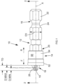
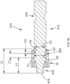
- a tool 10 for driving threaded fasteners includes a tool bit 12 and a floating magnet sleeve 14 removably received over the tool bit 12.
- the tool bit 12 includes extends along a longitudinal axis X and includes a rear shank portion 16, a front working end 18, and an intermediate portion 20 between the rear shank portion 16 and the front working end 18.
- the rear shank portion 16 has a polygonal (e.g., hexagonal) cross section 22 and an annular ball groove 24 so that the rear shank portion 16 is configured to be coupled to a tool bit holder or chuck of a power tool (e.g., a drill, impact driver, or screwdriver).
- a power tool e.g., a drill, impact driver, or screwdriver
- the front working end 18 is configured to engage a head of a threaded fastener.
- the front working end 18 has a Phillips #2 (PH2) geometry 26 for engaging a Phillips #2 head threaded fastener.
- PH2 Phillips #2
- the front working end 18 may have other configurations for engaging other types of threaded fastener heads, such as Phillips #1, Phillips #3, flat head, square, hex, star, and Torx (e.g., T20, T25, etc.).
- the intermediate portion 20 includes a front shoulder 28 proximate the working end 18, a rear shoulder 30 proximate the shank 16, and a reduced diameter annular groove 32 disposed between the front shoulder 28 and the rear shoulder 30.
- the intermediate potion 20 optionally may further include a second reduced diameter portion 33 between the rear shoulder 30 and the shank 16.
- the second reduced diameter 33 may comprise a torsion zone that twists and takes up stresses in response to excessive torque loads on the tool bit 12.
- the second reduced diameter portion 33 may comprise a groove for receiving a product label ring 31 disposed between the shank 16 and the rear shoulder 30.
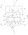
- the annular groove 32 has a circular cross section 35 with a first diameter D1.
- the front shoulder 28 has a nearly circular and partially polygonal cross-section with six arc-shaped portions 34 interposed with six short flat portions 36.
- the front shoulder 28 has a second diameter D2 (measured across the arc shaped portions 34), which is greater than the first diameter.
- the rear shoulder 30 has a polygonal (e.g., hex shaped) cross section defined by flat walls 38 connected by vertices 40.
- the rear shoulder 30 has a third diameter D3 (i.e., the maximum distance across the polygonal cross-section), which is greater than the second diameter D2, measured across a circle 42 defined by the vertices 40.
- the first diameter is approximately 5.0 mm to approximately 5.9 mm (e.g., approximately 5.45 mm)
- the second diameter is approximately 6.0 mm to approximately 6.9 mm (e.g., approximately 6.4 mm)
- the third diameter is approximately 7.0 mm to approximately 8.0 mm (e.g., approximately 7.18 mm).
- the rear shoulder 30 has the same cross-sectional shape and size as the polygonal portion 22 of the shank 16, although it should be understood that the cross-sectional shape and/or size of the rear shoulder 30 may be different than the polygonal portion 22 of the shank 16.
- the front shoulder 28 has a first ramped portion 44 at a front end 46 of the front shoulder 28 adjacent the working end 18 and a second ramped portion 46 at a rear end 48 of the front shoulder 28 adjacent the annular groove 32.
- the first ramped portion 44 is disposed at a first angle A1 relative to the longitudinal axis X, while the second ramped portion 46 being disposed at a second angle A2 to the longitudinal axis X.
- the rear shoulder 30 has a front wall 52 disposed at a third angle A3 to the longitudinal axis.
- the first angle A1 is less than the second angle A2 so that installation of the sleeve 14 over the front shoulder 28 in a rearward direction R requires less axial force than removal of sleeve 14 over the front shoulder in a forward direction F.
- the third angle A3 is greater than both the first angle A1 and the second angle A2 in order to inhibit the sleeve 14 from moving in the rearward direction R beyond the rear shoulder 30.
- the first angle is approximately 40° to approximately 50° (e.g., approximately 45°)
- the second angle is approximately 60° to approximately 70° (e.g., approximately 65°)
- the third angle is approximately 80° to approximately 100° (e.g., approximately perpendicular to the axis X).
- the front end 46 of the front shoulder 28 is disposed an axial length L3 from a tip 19 of the working end 18, such as approximately 7 mm to approximately 9 mm (e.g., approximately 8.57 mm).
- the front shoulder 28 has an axial length L1 between its front end 46 and the rear end 48, such as approximately such as approximately 1.4 mm to approximately 1.7 mm (e.g., approximately 1.55 mm).
- the front end of the rear shoulder 20 is disposed an axial length L2 from the tip 19 of the working end 18, such as approximately 12 mm to approximately 14 mm (e.g., approximately 13 mm).
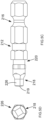
- the floating magnet sleeve 14 includes a generally tubular body 50 having a front end 52 and a rear end 54. Disposed in an annular groove 56 inside the rear end 54 of the body 50 is a retention member 58 that projects radially inward from a rear end 54 of the body 50 toward an interior of the tubular body 50.
- the retention member 58 comprises an O-ring or an elastic C-clip.
- Other embodiments of retention members 58, such as a ball, a spring band, etc., can be found in the aforementioned related patent applications listed in the first paragraph of this application.
- a magnet 60 e.g., a ring shaped magnet, is disposed in an internal groove 60 in the front end 52 of the body 50.
- the sleeve 14 is removably receivable over the working end 18 and the intermediate portion 20 of the tool bit 12 with the retention member 58 disposed in the annular groove 32 between the front shoulder 36 and the rear shoulder 30.
- the sleeve 14 is configured to float axially by a float distance FD between a rearward position where the retention member 58 abuts the rear shoulder 20 and a forward position where the retention member 58 abuts the front shoulder 36, such that the magnet 60 can engage a head of a fastener coupled to and being driven by the working end 18, as the sleeve approaches its forward position.
- the dimensions of the tool bit 12 have been optimized to enable the magnet sleeve 14 to be able to jump from the rearward position in the forward direction F to engage at least 80% of fasteners of the type driven by the working end 18.
- the heads of the working end 18 can be inserted a different depth into the heads of various fasteners. It can be determined that the working end 18 will be inserted into the heads of existing fasteners by a depth that is between a minimum depth and maximum depth.
- the tip distance TD is greater or equal to approximately 2.5 mm (e.g., between approximately 2.5 mm and 4.0 mm).
- the float distance FD i.e., the amount of distance that the sleeve 14 floats between the rear position and the forward position - must be sufficiently small so that the magnet will be able to "jump" forward to engage a fastener head, while being sufficiently large to enable the wide range of fasteners to engage the working end 18.
- the float distance FD should be less than the tip distance TD.
- the float distance is approximately 1.8 mm to approximately 2.1 mm (e.g., approximately 2.02 mm).
- the ratio between the float distance FD and the tip distance TD should be between 40% and 75% (e.g., between 45% and 65%). These dimensions optimize operation of the tool bit 12 and the sleeve 14 to enable at least 80% of PH2 fasteners to be automatically engaged by the magnet 60 when they are being driven by the PH2 working end 18.
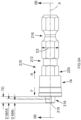
- a tool 210 for driving threaded fasteners includes a tool bit 212, similar to tool bit 12, and the same floating magnet sleeve 14, which can also be removably received over the tool bit 212.
- the tool bit 212 extends along a longitudinal axis X and includes a rear shank portion 216, a front working end 218, and an intermediate portion 220 between the rear shank portion 216 and the front working end 218.
- the rear shank portion 216 is identical to the rear shank portion 16 in the tool bit 12.
- the front working end 218 differs from the working end 16 of the tool bit 12 insofar as it has a Square Drive #2 (SQ2) geometry 226 for engaging a SQ2 head of a threaded fastener.
- the intermediate portion 220 has the same configuration as the intermediate portion 20, except that the dimensions and angles have been modified so that the bit has been optimized so that the floating magnet sleeve 14 will engage and work with at least 80% of fasteners with SQ2 heads.
- the optimized dimensions for the SQ2 embodiment of the tool bit 212 are set forth in Table 1 below.
- a tool 310 for driving threaded fasteners includes a tool bit 312, similar to tool bit 12, and the same floating magnet sleeve 14, which can also be removably received over the tool bit 312.
- the tool bit 312 extends along a longitudinal axis X and includes a rear shank portion 316, a front working end 318, and an intermediate portion 320 between the rear shank portion 316 and the front working end 318.
- the rear shank portion 316 is identical to the rear shank portion 16 in the tool bit 12.
- the front working end 318 differs from the working end 16 of the tool bit 12 insofar as it has a Torx ® T20 geometry 326 for engaging a Torx ® T20 head of a threaded fastener.
- the intermediate portion 320 has the same configuration as the intermediate portion 20, except that the dimensions and angles have been modified so that the bit has been optimized so that the floating magnet sleeve 14 will engage and work with at least 80% of fasteners with Torx ® T20 heads.
- the optimized dimensions for the Torx ® T20 embodiment of the tool bit 312 are set forth in Table 1 below.
- a tool 410 for driving threaded fasteners includes a tool bit 412, similar to tool bit 12, and the same floating magnet sleeve 14, which can also be removably received over the tool bit 412.
- the tool bit 412 extends along a longitudinal axis X and includes a rear shank portion 416, a front working end 418, and an intermediate portion 420 between the rear shank portion 416 and the front working end 418.
- the rear shank portion 416 is identical to the rear shank portion 16 in the tool bit 12.
- the front working end 418 differs from the working end 16 of the tool bit 12 insofar as it has a Torx ® T25 geometry 326 for engaging a Torx ® T25 head of a threaded fastener.
- the intermediate portion 420 has the same configuration as the intermediate portion 20, except that the dimensions and angles have been modified so that the bit has been optimized so that the floating magnet sleeve 14 will engage and work with at least 80% of fasteners with Torx ® T25 heads.
- the optimized dimensions for the Torx ® T25 embodiment of the tool bit 412 are set forth in Table 1 below.
- the front shoulder of the tool bits allows the floating magnet sleeve to be installed onto the tool bit easily, and retained during use.
- the dimensions and configuration of the annular groove allows floating magnet sleeve to jump forward to virtually all fasteners for greater retention and single handed use.
- the tool bit with the floating magnet sleeve have a narrow width to easily see work and provide access to cramped spaces.
- the tool bit has an overall length of 41mm or 1.61", which will outperform a standard 1" tool bits in torsion.
- Example embodiments have been provided so that this disclosure will be thorough, and to fully convey the scope to those who are skilled in the art. Numerous specific details are set forth such as examples of specific components, devices, and methods, to provide a thorough understanding of embodiments of the present disclosure. It will be apparent to those skilled in the art that specific details need not be employed, that example embodiments may be embodied in many different forms and that neither should be construed to limit the scope of the disclosure. In some example embodiments, well-known processes, well-known device structures, and well-known technologies are not described in detail.
- first, second, third, etc. may be used herein to describe various elements, components, regions, layers and/or sections, these elements, components, regions, layers and/or sections should not be limited by these terms. These terms may be only used to distinguish one element, component, region, layer or section from another region, layer or section. Terms such as “first,” “second,” and other numerical terms when used herein do not imply a sequence or order unless clearly indicated by the context. Thus, a first element, component, region, layer or section discussed below could be termed a second element, component, region, layer or section without departing from the teachings of the example embodiments.
- the invention may provide a tool in accordance with any one of the following numbered clauses, which, for the avoidance of doubt, not constitute part of the claims of this application.
Landscapes
- Engineering & Computer Science (AREA)
- Mechanical Engineering (AREA)
- Details Of Spanners, Wrenches, And Screw Drivers And Accessories (AREA)
Applications Claiming Priority (2)
| Application Number | Priority Date | Filing Date | Title |
|---|---|---|---|
| US201762527375P | 2017-06-30 | 2017-06-30 | |
| EP18180898.1A EP3470176A1 (de) | 2017-06-30 | 2018-06-29 | Werkzeugteile mit beweglichen magnethülsen |
Related Parent Applications (1)
| Application Number | Title | Priority Date | Filing Date |
|---|---|---|---|
| EP18180898.1A Division EP3470176A1 (de) | 2017-06-30 | 2018-06-29 | Werkzeugteile mit beweglichen magnethülsen |
Publications (2)
| Publication Number | Publication Date |
|---|---|
| EP4509268A2 true EP4509268A2 (de) | 2025-02-19 |
| EP4509268A3 EP4509268A3 (de) | 2025-04-30 |
Family
ID=62837784
Family Applications (2)
| Application Number | Title | Priority Date | Filing Date |
|---|---|---|---|
| EP18180898.1A Ceased EP3470176A1 (de) | 2017-06-30 | 2018-06-29 | Werkzeugteile mit beweglichen magnethülsen |
| EP25150119.3A Pending EP4509268A3 (de) | 2017-06-30 | 2018-06-29 | Werkzeugteile mit schwimmenden magnethülsen |
Family Applications Before (1)
| Application Number | Title | Priority Date | Filing Date |
|---|---|---|---|
| EP18180898.1A Ceased EP3470176A1 (de) | 2017-06-30 | 2018-06-29 | Werkzeugteile mit beweglichen magnethülsen |
Country Status (2)
| Country | Link |
|---|---|
| US (1) | US10792793B2 (de) |
| EP (2) | EP3470176A1 (de) |
Families Citing this family (3)
| Publication number | Priority date | Publication date | Assignee | Title |
|---|---|---|---|---|
| US11541518B2 (en) * | 2017-07-21 | 2023-01-03 | Snap-On Incorporated | Tool head with groove for removal from lug |
| US11794319B2 (en) * | 2021-10-13 | 2023-10-24 | Ming-Chang Chen | Screwdriver |
| USD1095200S1 (en) * | 2024-05-20 | 2025-09-30 | Jefe Hex LLC | Hex shank tap |
Family Cites Families (22)
| Publication number | Priority date | Publication date | Assignee | Title |
|---|---|---|---|---|
| US3253626A (en) | 1964-08-03 | 1966-05-31 | Gardner Denver Co | Magnetic tool |
| US7107882B1 (en) * | 2004-10-01 | 2006-09-19 | Chang Wun-Hai | Slip-resistant magnetic sheath for a screwdriver |
| DE102011000710A1 (de) | 2011-02-14 | 2012-08-16 | Wera-Werk Hermann Werner Gmbh & Co. Kg | Drehmomentübertragungseinrichtung in Form eines Bitfutters |
| US9227309B2 (en) * | 2012-02-15 | 2016-01-05 | Black & Decker Inc. | Quick change bit holder with ring magnet |
| US9505108B2 (en) * | 2012-02-15 | 2016-11-29 | Black & Decker Inc. | Bit holder with floating magnet sleeve |
| US9943946B2 (en) * | 2012-02-15 | 2018-04-17 | Black & Decker Inc. | Tool bits with floating magnet sleeves |
| US9156147B2 (en) * | 2012-02-15 | 2015-10-13 | Black & Decker Inc. | Quick change bit holder with ring magnet |
| US9597783B2 (en) | 2013-07-02 | 2017-03-21 | Chervon (Hk) Limited | Bit assembly |
| TWI556922B (zh) | 2014-01-22 | 2016-11-11 | Good Year Hardware Co Ltd | Tool head structure |
| US10093005B2 (en) | 2014-07-15 | 2018-10-09 | Chervon (Hk) Limited | Bit accessory and bit assembly |
| US20160023333A1 (en) | 2014-07-24 | 2016-01-28 | Jei Mou Industrial Co., Ltd. | Tool Head with a Screw Positioning Sleeve |
| TWI532569B (zh) | 2014-09-26 | 2016-05-11 | guo-han Liu | A screwdriver assembly tool |
| TWM501916U (zh) | 2015-02-25 | 2015-06-01 | Witman Corp | 起子頭之定位結構改良 |
| US20160279769A1 (en) | 2015-03-25 | 2016-09-29 | Yavuz Arslan | Screwdriver Bit Positioning Structure |
| US9718174B2 (en) | 2015-10-28 | 2017-08-01 | Chung-Yu Tsai | Hand tool assembly with magnetic securing device |
| US20170120428A1 (en) * | 2015-11-02 | 2017-05-04 | Compass Corporation | Screwdriver bit device with a magnetic structure |
| US9406423B1 (en) * | 2015-11-18 | 2016-08-02 | Chung-Yu Tsai | Magnetic sleeve assembly |
| US10124473B2 (en) * | 2016-04-15 | 2018-11-13 | Chia-Feng Chang | Screwdriver bit assembly with a magnetic structure |
| US10022847B2 (en) * | 2016-05-10 | 2018-07-17 | Chung-Yu Tsai | Magnetic sleeve for positioning screwdriver bit |
| US9833887B1 (en) * | 2016-09-21 | 2017-12-05 | Tsai-Fa Liu | Replaceable magnetic screw-locking depth positoining head |
| US10150206B2 (en) * | 2016-11-11 | 2018-12-11 | Ming-Hong Ko | Screwdriver tool |
| US20190118357A1 (en) * | 2017-10-25 | 2019-04-25 | Ting Ya Huang | Magnetic attraction structure for screw bit |
-
2018
- 2018-05-23 US US15/986,861 patent/US10792793B2/en active Active
- 2018-06-29 EP EP18180898.1A patent/EP3470176A1/de not_active Ceased
- 2018-06-29 EP EP25150119.3A patent/EP4509268A3/de active Pending
Also Published As
| Publication number | Publication date |
|---|---|
| US20200114498A1 (en) | 2020-04-16 |
| EP3470176A1 (de) | 2019-04-17 |
| EP4509268A3 (de) | 2025-04-30 |
| US10792793B2 (en) | 2020-10-06 |
Similar Documents
| Publication | Publication Date | Title |
|---|---|---|
| AU2019240548B2 (en) | Socket drive improvement | |
| US4218795A (en) | Drill bit with fastener-driving collar assembly | |
| US7121774B2 (en) | Clamping device for hexagon bits | |
| EP3195981B1 (de) | Antriebsführung zur befestigung von bits | |
| CN100389933C (zh) | 螺批头连接杆装置 | |
| CA3081901C (en) | Automatic double-action fastener installation tool | |
| CA1148338A (en) | Hole-drilling and fastener-driving combination tool | |
| US10759027B2 (en) | Socket and bit retention | |
| JP4662611B2 (ja) | 穴あけ及び締結具取付け用工具 | |
| EP4509268A2 (de) | Werkzeugteile mit schwimmenden magnethülsen | |
| US20080219790A1 (en) | Conduit reamer tool element | |
| US10953521B2 (en) | Driver | |
| KR100561176B1 (ko) | 드라이버 비트 및 드라이버 | |
| US9975232B2 (en) | Pin anchor driver | |
| US20230373066A1 (en) | Tool bit | |
| US20240051040A1 (en) | Step drill bit | |
| US8753048B2 (en) | Hole saw | |
| CN114729658A (zh) | 两件式单面紧固件和安装工具 | |
| AU2023203529A1 (en) | Socket drive improvement | |
| CN110682245A (zh) | 套接件 | |
| US20240359301A1 (en) | Driver bit | |
| EP3162506A1 (de) | Befestigungswerkzeuge mit beweglichen magnethülsen | |
| JP5670063B2 (ja) | ナットかしめ工具 | |
| CN115701376A (zh) | 防空程保持套筒 | |
| US20250170635A1 (en) | Knockout Punch Tool with Draw Stud |
Legal Events
| Date | Code | Title | Description |
|---|---|---|---|
| PUAI | Public reference made under article 153(3) epc to a published international application that has entered the european phase |
Free format text: ORIGINAL CODE: 0009012 |
|
| STAA | Information on the status of an ep patent application or granted ep patent |
Free format text: STATUS: THE APPLICATION HAS BEEN PUBLISHED |
|
| AC | Divisional application: reference to earlier application |
Ref document number: 3470176 Country of ref document: EP Kind code of ref document: P |
|
| AK | Designated contracting states |
Kind code of ref document: A2 Designated state(s): AL AT BE BG CH CY CZ DE DK EE ES FI FR GB GR HR HU IE IS IT LI LT LU LV MC MK MT NL NO PL PT RO RS SE SI SK SM TR |
|
| REG | Reference to a national code |
Ref country code: DE Ref legal event code: R079 Free format text: PREVIOUS MAIN CLASS: B25B0023120000 Ipc: B25B0023000000 |
|
| PUAL | Search report despatched |
Free format text: ORIGINAL CODE: 0009013 |
|
| AK | Designated contracting states |
Kind code of ref document: A3 Designated state(s): AL AT BE BG CH CY CZ DE DK EE ES FI FR GB GR HR HU IE IS IT LI LT LU LV MC MK MT NL NO PL PT RO RS SE SI SK SM TR |
|
| RIC1 | Information provided on ipc code assigned before grant |
Ipc: B25B 23/12 20060101ALI20250324BHEP Ipc: B25B 23/00 20060101AFI20250324BHEP |
|
| STAA | Information on the status of an ep patent application or granted ep patent |
Free format text: STATUS: REQUEST FOR EXAMINATION WAS MADE |
|
| 17P | Request for examination filed |
Effective date: 20251024 |
|
| STAA | Information on the status of an ep patent application or granted ep patent |
Free format text: STATUS: EXAMINATION IS IN PROGRESS |
|
| 17Q | First examination report despatched |
Effective date: 20260216 |