EP4509364A1 - Knotenadressenzuweisungsverfahren und -vorrichtung für fahrzeug sowie fahrzeugvorrichtung und speichermedium - Google Patents
Knotenadressenzuweisungsverfahren und -vorrichtung für fahrzeug sowie fahrzeugvorrichtung und speichermedium Download PDFInfo
- Publication number
- EP4509364A1 EP4509364A1 EP22952643.9A EP22952643A EP4509364A1 EP 4509364 A1 EP4509364 A1 EP 4509364A1 EP 22952643 A EP22952643 A EP 22952643A EP 4509364 A1 EP4509364 A1 EP 4509364A1
- Authority
- EP
- European Patent Office
- Prior art keywords
- node
- address
- addressing
- addressing instruction
- vehicle
- Prior art date
- Legal status (The legal status is an assumption and is not a legal conclusion. Google has not performed a legal analysis and makes no representation as to the accuracy of the status listed.)
- Pending
Links
Images


Classifications
-
- H—ELECTRICITY
- H04—ELECTRIC COMMUNICATION TECHNIQUE
- H04L—TRANSMISSION OF DIGITAL INFORMATION, e.g. TELEGRAPHIC COMMUNICATION
- H04L12/00—Data switching networks
- H04L12/28—Data switching networks characterised by path configuration, e.g. LAN [Local Area Networks] or WAN [Wide Area Networks]
- H04L12/40—Bus networks
-
- H—ELECTRICITY
- H04—ELECTRIC COMMUNICATION TECHNIQUE
- H04L—TRANSMISSION OF DIGITAL INFORMATION, e.g. TELEGRAPHIC COMMUNICATION
- H04L61/00—Network arrangements, protocols or services for addressing or naming
- H04L61/50—Address allocation
- H04L61/5038—Address allocation for local use, e.g. in LAN or USB networks, or in a controller area network [CAN]
-
- B—PERFORMING OPERATIONS; TRANSPORTING
- B60—VEHICLES IN GENERAL
- B60Q—ARRANGEMENT OF SIGNALLING OR LIGHTING DEVICES, THE MOUNTING OR SUPPORTING THEREOF OR CIRCUITS THEREFOR, FOR VEHICLES IN GENERAL
- B60Q3/00—Arrangement of lighting devices for vehicle interiors; Lighting devices specially adapted for vehicle interiors
- B60Q3/80—Circuits; Control arrangements
-
- H—ELECTRICITY
- H04—ELECTRIC COMMUNICATION TECHNIQUE
- H04L—TRANSMISSION OF DIGITAL INFORMATION, e.g. TELEGRAPHIC COMMUNICATION
- H04L12/00—Data switching networks
- H04L12/28—Data switching networks characterised by path configuration, e.g. LAN [Local Area Networks] or WAN [Wide Area Networks]
- H04L12/40—Bus networks
- H04L12/40006—Architecture of a communication node
-
- H—ELECTRICITY
- H04—ELECTRIC COMMUNICATION TECHNIQUE
- H04L—TRANSMISSION OF DIGITAL INFORMATION, e.g. TELEGRAPHIC COMMUNICATION
- H04L12/00—Data switching networks
- H04L12/28—Data switching networks characterised by path configuration, e.g. LAN [Local Area Networks] or WAN [Wide Area Networks]
- H04L12/40—Bus networks
- H04L12/40169—Flexible bus arrangements
-
- H—ELECTRICITY
- H04—ELECTRIC COMMUNICATION TECHNIQUE
- H04L—TRANSMISSION OF DIGITAL INFORMATION, e.g. TELEGRAPHIC COMMUNICATION
- H04L67/00—Network arrangements or protocols for supporting network services or applications
- H04L67/01—Protocols
- H04L67/12—Protocols specially adapted for proprietary or special-purpose networking environments, e.g. medical networks, sensor networks, networks in vehicles or remote metering networks
-
- B—PERFORMING OPERATIONS; TRANSPORTING
- B60—VEHICLES IN GENERAL
- B60Q—ARRANGEMENT OF SIGNALLING OR LIGHTING DEVICES, THE MOUNTING OR SUPPORTING THEREOF OR CIRCUITS THEREFOR, FOR VEHICLES IN GENERAL
- B60Q3/00—Arrangement of lighting devices for vehicle interiors; Lighting devices specially adapted for vehicle interiors
- B60Q3/20—Arrangement of lighting devices for vehicle interiors; Lighting devices specially adapted for vehicle interiors for lighting specific fittings of passenger or driving compartments; mounted on specific fittings of passenger or driving compartments
-
- H—ELECTRICITY
- H04—ELECTRIC COMMUNICATION TECHNIQUE
- H04L—TRANSMISSION OF DIGITAL INFORMATION, e.g. TELEGRAPHIC COMMUNICATION
- H04L12/00—Data switching networks
- H04L12/28—Data switching networks characterised by path configuration, e.g. LAN [Local Area Networks] or WAN [Wide Area Networks]
- H04L12/40—Bus networks
- H04L2012/40208—Bus networks characterized by the use of a particular bus standard
- H04L2012/40234—Local Interconnect Network LIN
-
- H—ELECTRICITY
- H04—ELECTRIC COMMUNICATION TECHNIQUE
- H04L—TRANSMISSION OF DIGITAL INFORMATION, e.g. TELEGRAPHIC COMMUNICATION
- H04L12/00—Data switching networks
- H04L12/28—Data switching networks characterised by path configuration, e.g. LAN [Local Area Networks] or WAN [Wide Area Networks]
- H04L12/40—Bus networks
- H04L2012/40267—Bus for use in transportation systems
- H04L2012/40273—Bus for use in transportation systems the transportation system being a vehicle
Definitions
- the present disclosure relates to the vehicle field, and more particularly, to a node address allocation method and apparatus for a vehicle, a vehicle, a device, and a storage medium.
- a configuration rate of vehicle interior ambient lights in family cars is increasing day by day, and use of multi-color RGB ambient lights is becoming more and more common.
- a quantity of ambient lights arranged in the car is also gradually increasing.
- a node address allocation method and apparatus for a vehicle, a vehicle, a device, and a storage medium are expected.
- the present disclosure provides a node address allocation method for a vehicle, including: obtaining, from a node set based on a first addressing mode, a node to which an address is currently to be allocated, the node set including a plurality of nodes connected to a first bus of the vehicle; obtaining an address of the node based on a quantity of addressing instruction frames in an addressing instruction sequence, an address carried by an addressing instruction frame currently issued to the node, and a frame quantity of the addressing instruction frame currently issued to the node; and performing address allocation on the node based on the address of the node.
- the obtaining, from the node set based on the first addressing mode, the node to which the address is currently to be allocated includes: performing a node lookup sequentially from a head node to a tail node in the node set, and in response to finding a first to-be-processed node for which the address allocation has not been performed, determining the to-be-processed node as the node to which the address is currently to be allocated; or, performing the node lookup sequentially from the tail node to the head node in the node set, and in response to finding the first to-be-processed node for which the address allocation has not been performed, determining the to-be-processed node as the node to which the address is currently to be allocated.
- the first addressing mode is one of an LSM addressing mode or a BSM addressing mode.
- the obtaining the address of the node based on the quantity of addressing instruction frames in the addressing instruction sequence, the address carried by the addressing instruction frame currently issued to the node, and the frame quantity of the addressing instruction frame currently issued to the node includes: obtaining a first difference between the quantity of addressing instruction frames in the addressing instruction sequence and the frame quantity of the addressing instruction frame currently issued to the node; obtaining a second difference between the address carried by the addressing instruction frame currently issued to the node and the first difference; and obtaining the address of the node based on the second difference.
- the node address allocation method further includes: obtaining, from the node set based on a second addressing mode, the node to which the address is currently to be allocated; obtaining the address of the node based on the address carried by the addressing instruction frame currently issued to the node in the addressing instruction sequence; and performing the address allocation on the node based on the address of the node.
- the second addressing mode is one of an LSM addressing mode or a BSM addressing mode, and the second addressing mode is different from the first addressing mode.
- the present disclosure provides a node address allocation apparatus for a vehicle.
- the apparatus includes: a node determination module configured to obtain, from a node set based on a first addressing mode, a node to which an address is currently to be allocated, the node set including a plurality of nodes connected to a first bus of the vehicle; an address determination module configured to obtain an address of the node based on a quantity of addressing instruction frames in an addressing instruction sequence, an address carried by an addressing instruction frame currently issued to the node, and a frame quantity of the addressing instruction frame currently issued to the node; and an allocation module configured to perform address allocation on the node based on the address of the node.
- the address determination module is specifically configured to: obtain a first difference between a quantity of addressing instruction frames in the addressing instruction sequence and the frame quantity of the addressing instruction frame currently issued to the node; obtain a second difference between the address carried by the addressing instruction frame currently issued to the node and the first difference; and obtain the address of the node based on the second difference.
- the present disclosure provides a vehicle including the node address allocation apparatus for the vehicle.
- the present disclosure provides an electronic device including a memory; a processor; and a computer program stored on the memory and executable on the processor.
- the processor is configured to, when executing the program, implement the node address allocation method for the vehicle according to any one of embodiments in the present disclosure.
- the present disclosure provides a computer-readable storage medium having a computer program stored thereon.
- the program is configured to, when executed by a processor, implement the node address allocation method for the vehicle according to any one of the embodiments in the present disclosure.
- the address of the node is obtained by obtaining the quantity of addressing instruction frames in an addressing instruction sequence, the address carried by the addressing instruction frame currently issued to the node, and the frame quantity of the addressing instruction frame currently issued to the node.
- This method can realize accurate control on the node address allocation, meeting predetermined requirements.
- the present disclosure generally relates to a vehicle field.
- the following embodiments of the present disclosure exemplarily illustrate a node address allocation method for a vehicle.
- the present disclosure provides a node address allocation method for a vehicle.
- the method includes operations at blocks.
- a node to which an address is currently to be allocated is obtained from a node set based on a first addressing mode.
- the node set includes a plurality of nodes connected to a first bus of the vehicle.
- a to-be-allocated node address is obtained from a set of all nodes based on a selected addressing mode.
- the set of nodes are all nodes connected to a bus of a current vehicle. For example, when the first bus of this vehicle is connected to three nodes, 3 to-be-allocated node address should also be provided.
- the address of the node may be 0x10, 0x0F, or 0x0E.
- a total quantity of nodes may be represented by Max NAD.
- the obtaining the node to which the address is currently to be allocated from the node set based on the first addressing mode includes: performing a node lookup sequentially from a head node to a tail node in the node set, and in response to finding a first to-be-processed node for which the address allocation has not been performed, determining the to-be-processed node as the node to which the address is currently to be allocated; or, performing the node lookup sequentially from the tail node to the head node in the node set, and in response to finding the first to-be-processed node for which the address allocation has not been performed, determining the to-be-processed node as the node to which the address is currently to be allocated.
- a Max NAD is sent to perform allocation with a largest NAD, and the allocation is performed in a descending order. That is, a node lookup is performed from the head node to the tail node in the node set. When the node has not been allocated with an address, the to-be-processed node is determined as the node to which the address needs to be allocated currently. Alternatively, a node lookup is performed from the tail node to the head node in the node set. When the node has not been allocated with an address, the to-be-processed node is determined as the node to which the address needs to be allocated currently.
- a first LIN node at a far end is identified by determining a current difference through a pull up current generator.
- An NAD to-be-allocated instruction is responded from far to near. That is, the node lookup is performed from the tail node to the head node in the node set.
- Indie Realplum chips adopt an LIN Switch Method (LSM) addressing mode. That is, by controlling on and off of the LIN Switch, a quantity of online slave nodes is increased. Starting from a first LIN node at a near end, slave nodes at the rear end are connected one by one from near to far, and the NAD allocation instruction is responded.
- LSM LIN Switch Method
- the first addressing mode is one of an LSM addressing mode or a BSM addressing mode.
- existing automatic addressing is mostly controlled by using Melexis MLX81 series chips or the Indie Realplum chips through LIN communication.
- the MLX81 series chips adopt the BSM addressing mode. That is, the first LIN node at the far end is identified by determining the current difference through the pull up current generator. The NAD allocation instruction is responded from far to near.
- the Indie Realplum chips adopt the LSM addressing mode. That is, by controlling the on and the off of the LIN Switch, the quantity of online slave nodes is increased. Starting from the first LIN node at the near end, the slave nodes at the rear end are connected one by one from near to far, and the NAD allocation instruction is responded.
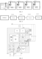
- FIG. 2 An internal structure of the MLX81 series chip is illustrated in FIG. 2 .
- the main steps are as follows:
- all LIN nodes are serially connected through daisy chain, as illustrated in FIG. 3 .
- the pull up current generator is switched on to perform the pre-measurement.
- the node is determined not to be the last node, and thus the pull up current generator needs to be switched off.
- Rslave is switched on to test the current value at this time, and whether the current value is greater than the predetermined current value is determined.
- the node is determined to be the last node, and NAD address allocation is performed.
- the predetermined current value is: 1.2 mA. After addressing in the BSM mode, the node address is illustrated in FIG. 4 .
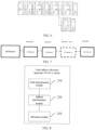
- the Indie Realplum chip adopts the LSM addressing mode.
- An internal structure of the chip for LIN nodes is illustrated in FIG. 5 .
- An LSM addressing node connection diagram of the chip is illustrated in FIG. 6 .
- a next LIN node is connected through an LIN switch inside a node. Then, by determining whether the NAD is an initial value to identify whether the address has been allocated, and a new NAD will cover the old one for a node when identifying the node that has not been allocated with the NAD. In this way, the LIN bus automatic address allocation can be realized.
- the steps are as follows:
- an address of the node is obtained based on a quantity of addressing instruction frames in an addressing instruction sequence, an address carried by an addressing instruction frame currently issued to the node, and a frame quantity of the addressing instruction frame currently issued to the node.
- the address of the node is obtained based on the quantity of addressing instruction frames in a current addressing sequence, the address carried by the addressing instruction, and a frame quantity of the current addressing instruction frame.
- a quantity of addresses can be expressed as the Max NAD.
- a first NAD allocation instruction frame with NAD being 0xX (Max NAD) is received. All nodes store the NAD being 0xX, where X is a quantity of addressing instruction frames in the addressing instruction sequence, and the LIN switch is switched off. All LIN switches are disconnected, and at this time, only the first node at the near end is online.
- a second NAD allocation instruction frame with NAD being 0x0 (X-1) is received. This node stores the NAD with Ox01 ⁇ Max NAD-(X-1) ⁇ , and the LIN switch is switched on and the second node is connected. The LIN switch for the first node is switched on, and at this time, a first node and a second node at the near end are online.
- the first node has NAD being Ox01, and the second node has NAD being 0xX.
- a NAD allocation instruction with NAD being 0x (X-2) is received.
- the node with NAD being 0xX is corrected to have NAD being 0x02 ⁇ Max NAD-(X-2) ⁇ , and the LIN switch for the second node is switched on and the third node is connected.
- the LIN switches for the first node and the second node are switched on, and at this time, three nodes at the near end are online.
- the first node has NAD being Ox01, the second node has NAD being 0x02, and the third node has NAD being 0xX.
- a NAD allocation instruction with NAD being 0x (X-3) is received.
- the node with NAD being 0xX is corrected to have NAD being 0x03 ⁇ Max NAD-(X-3) ⁇ , and the LIN switch for the second node is switched on. Until allocating to the last node, a second node at the far end is connected and online. A NAD allocation instruction with NAD being Ox01 is received. The node with NAD being 0xX is corrected to have NAD being 0x (X-1), and the LIN switch for this node is switched on. A first node at the far end is online, and this node has stored NAD being 0xX.
- the obtaining the address of the node based on the quantity of addressing instruction frames in the addressing instruction sequence, the address carried by the addressing instruction frame currently issued to the node, and the frame quantity of the addressing instruction frame currently issued to the node includes: obtaining a first difference between the quantity of addressing instruction frames in the addressing instruction sequence and the frame quantity of the addressing instruction frame currently issued to the node; obtaining a second difference between the address carried by the addressing instruction frame currently issued to the node and the first difference; and obtaining the address of the node based on the second difference.
- a difference is calculated as 2, and the current difference is the first difference.
- a difference is calculated as 3 based on the address carried by the addressing instruction frame being 5 and the first difference being 2, and the current difference is the second difference. Based on the second difference, the address of the node is obtained as NAD 0x03.
- address allocation is performed on the node based on the address of the node.
- the address allocation is performed on the node based on the address of the node, and the obtained address of each node is as illustrated in FIG. 4 .
- nodes in the LSM addressing mode and the BSM addressing mode are the same, and thus compatibility control is realized.
- the node address allocation method further includes: obtaining, from the node set based on a second addressing mode, the node to which the address is currently to be allocated; obtaining the address of the node based on the address carried by the addressing instruction frame currently issued to the node in the addressing instruction sequence; and performing the address allocation on the node based on the address of the node.
- the node to which the address is currently allocated is obtained from the node set based on a second addressing mode.
- the address carried by the addressing instruction frame currently issued to the node is directly taken as the address of the node. For example, when the node to which the address is currently to be allocated is 3, the obtained address of the node is 0x03.
- the second addressing mode is one of an LSM addressing mode or a BSM addressing mode, and the second addressing mode is different from the first addressing mode.
- the second addressing mode when the first addressing mode is the LSM addressing mode, the second addressing mode is the BSM addressing mode.
- the first addressing mode when the second addressing mode is the BSM addressing mode, the first addressing mode is the LSM addressing mode. Correspondence between the first addressing mode and the second addressing mode is adopted, allowing that NADs obtained though the two addressing modes are consistent, realizing the compatibility control.
- the address of the node is obtained by obtaining the quantity of addressing instruction frames in an addressing instruction sequence, the address carried by the addressing instruction frame currently issued to the node, and the frame quantity of the addressing instruction frame currently issued to the node. This method can realize accurate control on the address allocation on the node, meeting predetermined requirements.
- FIG. 8 illustrates a schematic diagram of a node address allocation apparatus for a vehicle according to an embodiment of the present disclosure.
- a node address allocation apparatus 200 for a vehicle includes a node determination module 210, an address determination module 220, and an allocation module 230.
- the node determination module 210 is configured to obtain, from a node set based on a first addressing mode, a node to which an address is currently to be allocated.
- the node set includes a plurality of nodes connected to a first bus of the vehicle.
- the address determination module 220 is configured to obtain an address of the node based on a quantity of addressing instruction frames in an addressing instruction sequence, an address carried by an addressing instruction frame currently issued to the node, and a frame quantity of the addressing instruction frame currently issued to the node.
- the allocation module 230 is configured to perform address allocation on the node based on the address of the node.
- the address determination module 220 is specifically configured to: obtain a first difference between a quantity of addressing instruction frames in the addressing instruction sequence and the frame quantity of the addressing instruction frame currently issued to the node; obtain a second difference between the address carried by the addressing instruction frame currently issued to the node and the first difference; and obtain the address of the node based on the second difference.
- the address of the node is obtained by obtaining the quantity of addressing instruction frames in the addressing instruction sequence, the address carried by the addressing instruction frame currently issued to the node, and the frame quantity of the addressing instruction frame currently issued to the node. This method can realize accurate control on the address allocation on the node, meeting predetermined requirements.
- each block in the flowchart or the block diagram may represent a module, a program segment, or portion of a code that contains one or more executable instructions for implementing a specified logical function.
- the functions noted in the blocks may also occur in a different order than those noted in the drawings. For example, two connected representations of blocks may actually be executed substantially in parallel. Sometimes, they may be executed in a reverse order, depending on the function involved.
- each block in the block diagrams and/or the flowcharts, and combinations of blocks in the block diagrams and/or the flowcharts may be implemented with a dedicated hardware-based system that performs specified functions or operational instructions, or may be implemented with a combination of dedicated hardware and computer instructions.
- the above description is only an explanation of preferred embodiments of the present disclosure and technical principles employed. It is conceivable for those skilled in the art that a scope of disclosure in the present disclosure is not limited to technical solutions formed by specific combinations of the above-described technical features, and should also cover other technical solutions formed by arbitrary combinations of the above-described technical features or their equivalents without departing from the concept of the above-described disclosure. For example, the above-mentioned features can be interchangeable with technical features disclosed in the present disclosure and having similar functions to form alternative technical solutions.
- the present disclosure provides a vehicle adopting the node address allocation apparatus 200 of the vehicle.
- the node address allocation apparatus 200 of the vehicle includes: the node determination module 210 configured to obtain, from the node set based on the first addressing mode, the node to which the address is currently to be allocated, the node set including the plurality of nodes connected to the first bus of the vehicle; the address determination module 220 configured to obtain the address of the node based on the quantity of addressing instruction frames in an addressing instruction sequence, the address carried by the addressing instruction frame currently issued to the node, and the frame quantity of the addressing instruction frame currently issued to the node; and the allocation module 230 configured to perform the address allocation on the node based on the address of the node.
- the address determination module 220 is specifically configured to: obtain the first difference between the quantity of addressing instruction frames in the addressing instruction sequence and the frame quantity of the addressing instruction frame currently issued to the node; obtain the second difference between the address carried by the addressing instruction frame currently issued to the node and the first difference; and obtain the address of the node based on the second difference.
- the address of the node is obtained by obtaining the quantity of addressing instruction frames in the addressing instruction sequence, the address carried by the addressing instruction frame currently issued to the node, and the frame quantity of the addressing instruction frame currently issued to the node. This method can realize accurate control on the address allocation on the node, meeting predetermined requirements.
- an electronic device includes a memory, a processor, and a computer program stored on the memory and executable on the processor.
- the electronic device is configured to, when executing the computer program, implement: obtaining, from the node set based on the first addressing mode, the node to which the address is currently to be allocated, the node set including the plurality of nodes connected to the first bus of the vehicle; obtaining the address of the node based on the quantity of addressing instruction frames in the addressing instruction sequence, the address carried by the addressing instruction frame currently issued to the node, and the frame quantity of the addressing instruction frame currently issued to the node; and performing the address allocation on the node based on the address of the node.
- the processor is configured to, when executing the computer program, further implement: performing the node lookup sequentially from the head node to the tail node in the node set, and in response to finding the first to-be-processed node for which the address allocation has not been performed, determining the to-be-processed node as the node to which the address is currently to be allocated; or, performing the node lookup sequentially from the tail node to the head node in the node set, and in response to finding the first to-be-processed node for which the address allocation has not been performed, determining the to-be-processed node as the node to which the address is currently to be allocated.
- the processor is configured to, when executing the computer program, further implement: obtaining the first difference between the quantity of addressing instruction frames in the addressing instruction sequence and the frame quantity of the addressing instruction frame currently issued to the node; obtaining the second difference between the address carried by the addressing instruction frame currently issued to the node and the first difference; and obtaining the address of the node based on the second difference.
- the processor is configured to, when executing the computer program, further implement: obtaining, from the node set based on the second addressing mode, the node to which the address is currently to be allocated; obtaining the address of the node based on the address carried by the addressing instruction frame currently issued to the node in the addressing instruction sequence; and performing the address allocation on the node based on the address of the node.
- the electronic device may be a terminal device, and an internal structure diagram thereof may be as illustrated in FIG. 9 .
- the terminal device includes a processor, a memory, a communication interface, a display screen, and an input apparatus connected by a system bus.
- the processor of the terminal device is used to provide computing and control capabilities.
- the memory of the terminal device includes a computer-readable storage medium and an internal memory.
- the computer-readable storage medium stores an operation system and the computer program.
- the internal memory provides an environment for operation of the operation system and the computer program in the computer-readable storage medium.
- the communication interface of the terminal device is used for wired or wireless communication with external terminals. Wireless communication can be realized through WIFI, operator network, near field communication (NFC), or other technologies.
- the computer program is configured to, when executed by the processor, implement an application opening method.
- the display screen of the terminal device may be a liquid crystal display screen or a communication ink display screen.
- the input apparatus of the terminal device may be a touch layer covered at the display screen, and may also be a key, a trackball, or a touch pad arranged at an outer housing of the terminal device, or may further be an external keyboard, a touch pad, or a mouse.
- the address of the node is obtained by obtaining the quantity of addressing instruction frames in the addressing instruction sequence, the address carried by the addressing instruction frame currently issued to the node, and the frame quantity of the addressing instruction frame currently issued to the node. This method can realize accurate control on the address allocation on the node, meeting predetermined requirements.
- a computer-readable storage medium has a computer program stored thereon.
- the computer program is configured to, when executed by a processor, implement: obtaining, from the node set based on the first addressing mode, the node to which the address is currently to be allocated, the node set including the plurality of nodes connected to the first bus of the vehicle; obtaining the address of the node based on the quantity of addressing instruction frames in the addressing instruction sequence, the address carried by the addressing instruction frame currently issued to the node, and the frame quantity of the addressing instruction frame currently issued to the node; and performing the address allocation on the node based on the address of the node.
- the processor is configured to, when executing the computer program, further implement: performing the node lookup sequentially from the head node to the tail node in the node set, and in response to finding the first to-be-processed node for which the address allocation has not been performed, determining the to-be-processed node as the node to which the address is currently to be allocated; or, performing the node lookup sequentially from the tail node to the head node in the node set, and in response to finding the first to-be-processed node for which the address allocation has not been performed, determining the to-be-processed node as the node to which the address is currently to be allocated.
- the processor is configured to, when executing the computer program, further implement: obtaining the first difference between the quantity of addressing instruction frames in the addressing instruction sequence and the frame quantity of the addressing instruction frame currently issued to the node; obtaining the second difference between the address carried by the addressing instruction frame currently issued to the node and the first difference; and obtaining the address of the node based on the second difference.
- the processor is configured to, when executing the computer program, further implement: obtaining, from the node set based on the second addressing mode, the node to which the address is currently to be allocated; obtaining the address of the node based on the address carried by the addressing instruction frame currently issued to the node in the addressing instruction sequence; and performing the address allocation on the node based on the address of the node.
- the address of the node is obtained by obtaining the quantity of addressing instruction frames in the addressing instruction sequence, the address carried by the addressing instruction frame currently issued to the node, and the frame quantity of the addressing instruction frame currently issued to the node. This method can realize accurate control on the address allocation on the node, meeting predetermined requirements.
- the computer program can be stored in the computer-readable storage medium.
- the computer program can include the processes of the embodiments of the methods described above.
- Any reference to the memory, a database, or other medium used in the embodiments provided herein may include at least one of the computer-readable storage medium and a computer-unreadable storage medium.
- a computer-readable memory may include a Read-Only Memory (ROM), a magnetic tape, a floppy disk, a flash memory, an optical memory, or the like.
- a volatile memory may include a Random Access Memory (RAM) or an external cache memory.
- RAM is available in a variety of forms, such as a Static Random Access Memory (SRAM), a Dynamic Random Access Memory (DRAM), or the like.
- orientation or the position indicated by terms such as “length,” “width,” “over,” “below,” “front,” “rear,” “left,” “right,” “vertical,” “horizontal,” “top,” “bottom,” “inner,” and “outer” should be construed to refer to the orientation and the position as shown in the drawings, and is only for the convenience of describing the present disclosure and simplifying the description, rather than indicating or implying that the pointed device or element must have a specific orientation, or be constructed and operated in a specific orientation, and therefore cannot be understood as a limitation of the present disclosure.
Landscapes
- Engineering & Computer Science (AREA)
- Computer Networks & Wireless Communication (AREA)
- Signal Processing (AREA)
- Mechanical Engineering (AREA)
- Health & Medical Sciences (AREA)
- Computing Systems (AREA)
- General Health & Medical Sciences (AREA)
- Medical Informatics (AREA)
- Small-Scale Networks (AREA)
- Arrangements Of Lighting Devices For Vehicle Interiors, Mounting And Supporting Thereof, Circuits Therefore (AREA)
Applications Claiming Priority (2)
| Application Number | Priority Date | Filing Date | Title |
|---|---|---|---|
| CN202210896197.6A CN115230578B (zh) | 2022-07-27 | 车辆的节点地址分配方法、装置、车辆设备及存储介质 | |
| PCT/CN2022/113386 WO2024021201A1 (zh) | 2022-07-27 | 2022-08-18 | 车辆的节点地址分配方法、装置、车辆设备及存储介质 |
Publications (2)
| Publication Number | Publication Date |
|---|---|
| EP4509364A1 true EP4509364A1 (de) | 2025-02-19 |
| EP4509364A4 EP4509364A4 (de) | 2025-07-23 |
Family
ID=83676565
Family Applications (1)
| Application Number | Title | Priority Date | Filing Date |
|---|---|---|---|
| EP22952643.9A Pending EP4509364A4 (de) | 2022-07-27 | 2022-08-18 | Knotenadressenzuweisungsverfahren und -vorrichtung für fahrzeug sowie fahrzeugvorrichtung und speichermedium |
Country Status (5)
| Country | Link |
|---|---|
| US (1) | US20250150431A1 (de) |
| EP (1) | EP4509364A4 (de) |
| JP (1) | JP7789960B2 (de) |
| KR (1) | KR20250012656A (de) |
| WO (1) | WO2024021201A1 (de) |
Family Cites Families (9)
| Publication number | Priority date | Publication date | Assignee | Title |
|---|---|---|---|---|
| US8645580B2 (en) * | 2011-09-06 | 2014-02-04 | Semiconductor Components Industries, Llc | Circuit and electronic module for automatic addressing |
| WO2013145255A1 (ja) | 2012-03-30 | 2013-10-03 | 富士通株式会社 | 電力供給制御装置、中継ノード装置、有線アドホックネットワークシステム、および電力供給制御方法 |
| KR101612834B1 (ko) * | 2014-12-23 | 2016-04-26 | 현대자동차주식회사 | 차량 내 lin 통신에서의 lin id 자동 할당 및 설정 방법 및 그를 위한 장치 |
| DE102017128489B4 (de) * | 2017-09-26 | 2025-08-14 | Elmos Semiconductor Se | Selbsttestfähiges Bussystem und Verwendung dieser Selbsttestfähigkeit zur Vergabe von Busknotenadressen mit einer Erkennung der Vertauschung von Eingängen und Ausgängen |
| EP3478031B1 (de) * | 2017-10-30 | 2020-06-24 | Melexis Technologies NV | Busprotokoll für dynamische beleuchtungsanwendung |
| CN110083628B (zh) * | 2019-05-08 | 2023-04-07 | 深圳市元征科技股份有限公司 | 一种车辆电子控制单元ecu的寻址方法及装置 |
| CN110830349B (zh) * | 2019-11-15 | 2021-05-28 | 宁波兴为汽车电子有限公司 | 一种可通用的车用lin开关从控制模块的地址分配方法 |
| CN111787667A (zh) * | 2020-05-22 | 2020-10-16 | 南京天擎汽车电子有限公司 | 氛围灯编址系统、电子装置及车辆 |
| CN114615777A (zh) * | 2020-12-09 | 2022-06-10 | 浙江宇视科技有限公司 | 灯板地址分配方法、装置、设备和介质 |
-
2022
- 2022-08-18 EP EP22952643.9A patent/EP4509364A4/de active Pending
- 2022-08-18 WO PCT/CN2022/113386 patent/WO2024021201A1/zh not_active Ceased
- 2022-08-18 JP JP2024568636A patent/JP7789960B2/ja active Active
- 2022-08-18 KR KR1020247042903A patent/KR20250012656A/ko active Pending
-
2025
- 2025-01-10 US US19/015,701 patent/US20250150431A1/en active Pending
Also Published As
| Publication number | Publication date |
|---|---|
| US20250150431A1 (en) | 2025-05-08 |
| EP4509364A4 (de) | 2025-07-23 |
| WO2024021201A1 (zh) | 2024-02-01 |
| JP7789960B2 (ja) | 2025-12-22 |
| JP2025519072A (ja) | 2025-06-24 |
| CN115230578A (zh) | 2022-10-25 |
| KR20250012656A (ko) | 2025-01-24 |
Similar Documents
| Publication | Publication Date | Title |
|---|---|---|
| EP2023150B1 (de) | Automatisches Analysegerät und Verfahren zu seiner Verwendung | |
| US6972755B2 (en) | Driver circuit for a display device | |
| ES2974531T3 (es) | Aparato de etiquetado de tubo de ensayo capaz de etiquetado secuencial y medio de grabación que almacena un programa para operar el mismo | |
| EP4425251A1 (de) | Kalibrierungsverfahren und -vorrichtung für elektrochrome vorrichtung und elektrochrome vorrichtung | |
| US20190146039A1 (en) | Method for Determining the Internal Resistance of Battery Cells, Battery Module, and Device | |
| EP4509364A1 (de) | Knotenadressenzuweisungsverfahren und -vorrichtung für fahrzeug sowie fahrzeugvorrichtung und speichermedium | |
| GB2190755A (en) | Battery level indicators | |
| CN109792398A (zh) | 车载通信系统、切换装置及车载通信方法 | |
| CN103983921A (zh) | 电源板检测方法及设备 | |
| CN111983491A (zh) | 一种电池模组的多路电阻测试系统及方法 | |
| US20230252538A1 (en) | Systems and methods for updating electronic labels based on product position | |
| US8762799B2 (en) | Method for checking the functional ability of a memory element | |
| CN115230578B (zh) | 车辆的节点地址分配方法、装置、车辆设备及存储介质 | |
| US20230266398A1 (en) | Method to compensate measurement error in a battery management system | |
| US6351258B1 (en) | Switcher system and I/O switching method | |
| CN118175138A (zh) | 一种电池管理系统从控模块识别地址自动分配电路及方法 | |
| CN118311329A (zh) | 阻抗检测电路、芯片、显示装置和方法 | |
| US20200174614A1 (en) | Touch and display driver, driving method, host and touch display apparatus | |
| CN110333448A (zh) | 电动汽车及动力电池的能量状态soe计算方法、装置 | |
| KR20010003805A (ko) | 다수의 배터리를 사용하는 단말기의 전원 제어 장치 및 방법 | |
| KR20220107462A (ko) | 배터리 불량 진단 장치 및 방법 | |
| US6972571B2 (en) | Load board with embedded relay tracker | |
| JP3567371B2 (ja) | マトリクス検査方法及び装置 | |
| CN116736124A (zh) | 电池放电能力的评估方法、装置、电子设备及存储介质 | |
| CN119623376B (zh) | Damq的信用控制验证组件、系统和方法 |
Legal Events
| Date | Code | Title | Description |
|---|---|---|---|
| STAA | Information on the status of an ep patent application or granted ep patent |
Free format text: STATUS: THE INTERNATIONAL PUBLICATION HAS BEEN MADE |
|
| PUAI | Public reference made under article 153(3) epc to a published international application that has entered the european phase |
Free format text: ORIGINAL CODE: 0009012 |
|
| STAA | Information on the status of an ep patent application or granted ep patent |
Free format text: STATUS: REQUEST FOR EXAMINATION WAS MADE |
|
| 17P | Request for examination filed |
Effective date: 20241112 |
|
| AK | Designated contracting states |
Kind code of ref document: A1 Designated state(s): AL AT BE BG CH CY CZ DE DK EE ES FI FR GB GR HR HU IE IS IT LI LT LU LV MC MK MT NL NO PL PT RO RS SE SI SK SM TR |
|
| REG | Reference to a national code |
Ref country code: DE Ref legal event code: R079 Free format text: PREVIOUS MAIN CLASS: B60Q0003800000 Ipc: H04L0012400000 |
|
| A4 | Supplementary search report drawn up and despatched |
Effective date: 20250623 |
|
| RIC1 | Information provided on ipc code assigned before grant |
Ipc: H04L 12/40 20060101AFI20250616BHEP Ipc: B60Q 3/80 20170101ALI20250616BHEP Ipc: H04L 61/5038 20220101ALI20250616BHEP Ipc: H04L 67/12 20220101ALI20250616BHEP |
|
| DAV | Request for validation of the european patent (deleted) | ||
| DAX | Request for extension of the european patent (deleted) |