EP4509405A1 - System zur kühlung eines flugzeugbordküchenwagens - Google Patents
System zur kühlung eines flugzeugbordküchenwagens Download PDFInfo
- Publication number
- EP4509405A1 EP4509405A1 EP23275121.4A EP23275121A EP4509405A1 EP 4509405 A1 EP4509405 A1 EP 4509405A1 EP 23275121 A EP23275121 A EP 23275121A EP 4509405 A1 EP4509405 A1 EP 4509405A1
- Authority
- EP
- European Patent Office
- Prior art keywords
- trolley
- cooling compartment
- compartment
- cold air
- trolley cooling
- Prior art date
- Legal status (The legal status is an assumption and is not a legal conclusion. Google has not performed a legal analysis and makes no representation as to the accuracy of the status listed.)
- Pending
Links
Images
Classifications
-
- B—PERFORMING OPERATIONS; TRANSPORTING
- B64—AIRCRAFT; AVIATION; COSMONAUTICS
- B64D—EQUIPMENT FOR FITTING IN OR TO AIRCRAFT; FLIGHT SUITS; PARACHUTES; ARRANGEMENT OR MOUNTING OF POWER PLANTS OR PROPULSION TRANSMISSIONS IN AIRCRAFT
- B64D11/00—Passenger or crew accommodation; Flight-deck installations not otherwise provided for
- B64D11/04—Galleys
-
- B—PERFORMING OPERATIONS; TRANSPORTING
- B64—AIRCRAFT; AVIATION; COSMONAUTICS
- B64D—EQUIPMENT FOR FITTING IN OR TO AIRCRAFT; FLIGHT SUITS; PARACHUTES; ARRANGEMENT OR MOUNTING OF POWER PLANTS OR PROPULSION TRANSMISSIONS IN AIRCRAFT
- B64D11/00—Passenger or crew accommodation; Flight-deck installations not otherwise provided for
- B64D11/0007—Devices specially adapted for food or beverage distribution services
-
- A—HUMAN NECESSITIES
- A47—FURNITURE; DOMESTIC ARTICLES OR APPLIANCES; COFFEE MILLS; SPICE MILLS; SUCTION CLEANERS IN GENERAL
- A47B—TABLES; DESKS; OFFICE FURNITURE; CABINETS; DRAWERS; GENERAL DETAILS OF FURNITURE
- A47B31/00—Service or tea tables, trolleys, or wagons
- A47B31/02—Service or tea tables, trolleys, or wagons with heating, cooling or ventilating means
-
- A—HUMAN NECESSITIES
- A47—FURNITURE; DOMESTIC ARTICLES OR APPLIANCES; COFFEE MILLS; SPICE MILLS; SUCTION CLEANERS IN GENERAL
- A47B—TABLES; DESKS; OFFICE FURNITURE; CABINETS; DRAWERS; GENERAL DETAILS OF FURNITURE
- A47B31/00—Service or tea tables, trolleys, or wagons
- A47B31/06—Service or tea tables, trolleys, or wagons adapted to the use in vehicles
-
- A—HUMAN NECESSITIES
- A47—FURNITURE; DOMESTIC ARTICLES OR APPLIANCES; COFFEE MILLS; SPICE MILLS; SUCTION CLEANERS IN GENERAL
- A47B—TABLES; DESKS; OFFICE FURNITURE; CABINETS; DRAWERS; GENERAL DETAILS OF FURNITURE
- A47B31/00—Service or tea tables, trolleys, or wagons
- A47B31/02—Service or tea tables, trolleys, or wagons with heating, cooling or ventilating means
- A47B2031/023—Service or tea tables, trolleys, or wagons with heating, cooling or ventilating means being dockable to a stationary refrigeration and heating unit
-
- B—PERFORMING OPERATIONS; TRANSPORTING
- B64—AIRCRAFT; AVIATION; COSMONAUTICS
- B64D—EQUIPMENT FOR FITTING IN OR TO AIRCRAFT; FLIGHT SUITS; PARACHUTES; ARRANGEMENT OR MOUNTING OF POWER PLANTS OR PROPULSION TRANSMISSIONS IN AIRCRAFT
- B64D13/00—Arrangements or adaptations of air-treatment apparatus for aircraft crew or passengers, or freight space
- B64D13/06—Arrangements or adaptations of air-treatment apparatus for aircraft crew or passengers, or freight space the air being conditioned
- B64D2013/0603—Environmental Control Systems
- B64D2013/0629—Environmental Control Systems with subsystems for cooling food, catering or special loads
Definitions
- This disclosure relates to aircraft galleys, and in particular to a system for cooling aircraft galley trolley compartments.
- the present disclosure provides a system for cooling an aircraft galley trolley, the system comprising: a trolley cooling compartment for stowing an aircraft galley trolley; and a heat exchanger arranged to provide cold air to the trolley cooling compartment; wherein the trolley cooling compartment defines an inlet arranged proximal to the base of the trolley cooling compartment for receiving the cold air; wherein the trolley cooling compartment is arranged to cool the aircraft galley trolley through the transfer of heat to the cold air; and wherein the transfer of heat to the cold air heats the cold air to produce warmer air.
- the cold air may be any suitable and desired temperature for cooling the aircraft galley trolley, e.g. less than 15 °C, e.g. less than 10 °C, e.g. less than 5 °C.
- the warmer air may be cooler than air in the aircraft cabin.
- the warmer air, while warmer than the cold air may be less than 20 °C, e.g. less than 15 °C, e.g. less than 10 °C.
- the heat exchanger is arranged to receive the warmer air; and the heat exchanger is arranged to cool the warmer air to provide the cold air.
- the trolley cooling compartment defines an outlet arranged proximal to a top of the trolley cooling compartment for expelling the warmer air.
- the heat exchanger is adjacent to the trolley cooling compartment.
- the heat exchanger may be positioned within four trolley compartment widths of the trolley cooling compartment, e.g. the heat exchanger may be positioned within 3 m of the trolley cooling compartment, e.g. within 2.5 m, e.g. within 2 m.
- the heat exchanger is to the side of, e.g. directly beside, the trolley cooling compartment.
- the heat exchanger is below, e.g. directly below, the trolley cooling compartment.
- the trolley cooling compartment comprises a first trolley cooling compartment for stowing a first aircraft galley trolley.
- the system further comprises a second trolley cooling compartment for stowing a second aircraft galley trolley; wherein the second trolley cooling compartment is arranged to cool the second aircraft galley trolley through the transfer of heat to the cold air; and wherein the transfer of heat to the cold air heats the cold air to produce warmer air.
- the second trolley cooling compartment is fluidly connected to the first trolley cooling compartment so to provide the cold air to the second trolley cooling compartment.
- Fluidly connected may be defined as in flow communication, i.e. air may flow between fluidly connected objects.
- the second trolley cooling compartment shares an adjoining wall with the first trolley cooling compartment; and the adjoining wall defines an opening arranged proximal to a base of the adjoining wall for providing the cold air from the first trolley cooling compartment to the second trolley cooling compartment.
- system further comprises: a fan arranged to promote transfer of the cold air from the first trolley cooling compartment to the second trolley cooling compartment at the opening defined by the adjoining wall.
- the fan arranged to promote transfer of the cold air from the first trolley cooling compartment to the second trolley cooling compartment at the opening defined by the adjoining wall is located within the opening.
- the opening comprises a first opening.
- the adjoining wall defines a second opening proximal to a top of the adjoining wall for expelling the warmer air from the second trolley cooling compartment to the first trolley cooling compartment.
- the system comprises: a fan arranged to promote transfer of the warmer air from the second trolley cooling compartment to the first trolley cooling compartment at the second opening defined by the adjoining wall.
- the fan arranged to promote transfer of the warmer air from the second trolley cooling compartment to the first trolley cooling compartment at the second opening defined by the adjoining wall is located within the second opening.
- the system further comprises a third trolley cooling compartment for stowing a third aircraft galley trolley; wherein the third trolley cooling compartment is arranged to cool the third aircraft galley trolley through the transfer of heat to the cold air; and wherein the transfer of heat to the cold air heats the cold air to produce warmer air.
- the third trolley cooling compartment is fluidly connected to the second trolley cooling compartment so to provide the cold air to the third trolley cooling compartment.
- the third trolley cooling compartment shares an adjoining wall with the second trolley cooling compartment; wherein the adjoining wall defines an opening arranged proximal to a base of the adjoining wall for providing the cold air from the second trolley cooling compartment to the third trolley cooling compartment.
- the adjoining wall further defines an opening proximal to a top of the adjoining wall for expelling the warmer air from the third trolley cooling compartment to the second trolley cooling compartment.
- the third trolley cooling compartment is fluidly connected to the first trolley cooling compartment so to provide the cold air to the third trolley cooling compartment.
- At least one of the second trolley cooling compartment or the third trolley cooling compartment is not in direct fluid communication with the heat exchanger.
- the second trolley cooling compartment and/or the third trolley cooling compartment may only be in fluid communication with the heat exchanger via the first trolley cooling compartment.
- the second trolley cooling compartment may only be in fluid communication with the heat exchanger via the first trolley cooling compartment; and the third trolley cooling compartment may only be in fluid communication with the heat exchanger via the first trolley cooling compartment and the second cooling compartment in combination.
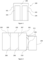
- Figure 1 shows a trolley cooling compartment 100 for cooling one or more aircraft galley trolleys 103, 104.
- the compartment 100 is installed within a galley of an aircraft.
- the compartment comprises a first section 101 and a second section 102.
- a first trolley 103 is positioned within the first section 101 for cooling and a second trolley 104 is positioned within the second compartment 102 for cooling.
- the division 105 between the sections 101, 102 may physically separate the first section 101 from the second section 102, i.e. the division 105 may be a physical divider.
- a physical separation between the first section 101 and the second section 102 may help to stow the trolleys 103, 104 within their respective sections 101, 102.
- the division 105 may denote the hypothetical divide between the first section 101 and the second section 102.
- the first section 101 and the second section 102 are in flow communication, i.e. air can pass freely between the sections 101, 102.
- the trolley cooling compartment 100 is filled with cold air in order to cool the trolleys 103, 104.
- the compartment and/or the trolleys are arranged to allow the cooling air to enter the trolleys 103, 104, to provide both internal and external cooling.
- the compartment and/or the trolleys are arranged to allow the cooling air to provide only external cooling to the trolleys 103, 104.
- the trolleys 103, 104 may require cooling to keep their contents cool, for example in order to keep food and beverage at a cool temperature.
- FIG 2 shows three trolley cooling compartments 201, 202, 203 for cooling trolleys in the galley of an aircraft.
- Each compartment 201, 202, 203 may be a trolley cooling compartment such as the compartment shown in Figure 1 .
- the compartments 201, 202, 203 are arranged to be cooled by a heat exchanger 204, i.e. a chiller.
- the heat exchanger 204 may be, for example, an air conditioning unit.
- the heat exchanger for cooling trolley compartments is commonly positioned in the galley above the level of the trolley compartments. This requires a significant amount of ducting in order to connect a heat exchanger to the trolley cooling compartments.
- the heat exchanger 204 is adjacent the first compartment 201, so only a very small amount of ducting 205 may be needed to connect the heat exchanger 204 to the first compartment 201.
- cold air from the heat exchanger 204 enters the first compartment 201 via an inlet 210 towards (e.g. proximal) the base of the first compartment 201.
- Warmer air (that has been warmed by the heat that it has removed from the trolleys in the trolley compartments) leaves the first compartment 201 via an outlet 211 towards (e.g. proximal) the top of the first compartment 201, for cooling by the heat exchanger 204 and subsequent recirculation. While the warmer air is warmer than the cooling air, it may still be cooler than the air of the aircraft cabin. Therefore, it may be energy efficient to supply the heat exchanger 204 with the warmer air from the outlet 211, e.g. compared with using ambient air.
- first trolley cooling compartment 201 proximal to the heat exchanger 204, is fluidly connected to the second compartment 202 via a first opening 206 and a second opening 207.
- the first opening 206 and the second opening 207 are located in a wall between the first trolley cooling compartment 201 and the second compartment 202.
- the first opening 206 and the second opening 207 may be provided at similar (e.g. the same) heights as the inlet 210 and the outlet 211 respectively.
- cooling air from the heat exchanger 204 may be provided to the second compartment 202 via the first compartment 201. Therefore, no ducting 205 may be needed to fluidly connect the heat exchanger 204 to the second compartment 202.
- the third compartment 203 may be fluidly connected to the second compartment 202 via a third opening 208 and a fourth opening 209.
- the third opening 208 and the fourth opening 209 are located in a wall between the second compartment 202 and the third compartment 203.
- the third opening 208 and the fourth opening 209 may be provided at similar (e.g. the same) heights as the inlet 210 and the outlet 211 respectively and/or at similar (e.g. the same) heights as the first opening 206 and the second opening 207 respectively.
- a first fan is positioned within the first opening 206 to promote air flow from the first compartment 201 to the second compartment 202.
- a second fan may be positioned within the second opening 207 to promote air flow from the second compartment 202 to the first compartment 201.
- the third opening 208 and the fourth opening 209 may also house respective third and fourth fans to promote air flow between the second compartment 202 and the third compartment 203. These fans may be low power fans, as convection of the air through the compartments may also be driven by thermal convection forces.
- cold air enters towards the base of the compartments 201, 202, 203, such that they fill with cold air. Circulation of the air occurs primarily as a result of naturally occurring convection currents, such that a significant amount of energy may be saved. In addition, no costly high power fans or pumps may be required, which saves weight on the aircraft.
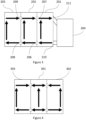
- Figure 3 shows a simplified path of the convection currents through the system of Figure 2 , as cold air is introduced to the system from the heat exchanger 204.
- cold air enters the inlet 210 from the heat exchanger 204.
- the compartment 201 fills with cold air, which cools its contents.
- Relatively warmer air which is heated up as a result of cooling the contents of the first compartment 201, exits the first compartment 201 via the outlet 211.
- a fan may be used as described above.
- the air flow in the second compartment 202 follows a similar path to the air flow in the first compartment 201, as shown. Hence, the warmer air leaves via the second opening 207.
- a fan may be used as described above.
- the various inlets, outlets and openings may be positioned to facilitate this.
- the inlet 210, the first opening 206 and the third opening 208 are positioned towards (e.g. proximal) the base of their respective compartments, as they are for the transfer of cold air through the system.
- the outlet 211, second opening 207 and fourth opening 209 are positioned towards (e.g. proximal) the top of their respective compartments, as they are for the transfer of warmer air through the system.
- heat exchanger may be connected to any of the compartments 201, 202, 203.
- the heat exchanger 204 could instead be adjacent to, and connected to, the second, central, compartment 202 of the three compartments 201, 202, 203 shown.
- FIG. 4 An example of this arrangement is shown in Figure 4 in which a heat exchanger (not shown) is adjacent to the central trolley cooling compartment 301.
- the heat exchanger may be behind the central cooling compartment 301 or immediately below the central trolley cooling compartment 301.
- the central trolley cooling compartment 301 is fluidly connected to each of the side trolley cooling compartments 302, 303. The path of the convection of air through the compartments 301, 302, 303 is also shown.
Landscapes
- Engineering & Computer Science (AREA)
- Aviation & Aerospace Engineering (AREA)
- Physics & Mathematics (AREA)
- Thermal Sciences (AREA)
Priority Applications (2)
| Application Number | Priority Date | Filing Date | Title |
|---|---|---|---|
| EP23275121.4A EP4509405A1 (de) | 2023-08-18 | 2023-08-18 | System zur kühlung eines flugzeugbordküchenwagens |
| US18/676,990 US20250058876A1 (en) | 2023-08-18 | 2024-05-29 | System for cooling an aircraft galley trolley |
Applications Claiming Priority (1)
| Application Number | Priority Date | Filing Date | Title |
|---|---|---|---|
| EP23275121.4A EP4509405A1 (de) | 2023-08-18 | 2023-08-18 | System zur kühlung eines flugzeugbordküchenwagens |
Publications (1)
| Publication Number | Publication Date |
|---|---|
| EP4509405A1 true EP4509405A1 (de) | 2025-02-19 |
Family
ID=87760364
Family Applications (1)
| Application Number | Title | Priority Date | Filing Date |
|---|---|---|---|
| EP23275121.4A Pending EP4509405A1 (de) | 2023-08-18 | 2023-08-18 | System zur kühlung eines flugzeugbordküchenwagens |
Country Status (2)
| Country | Link |
|---|---|
| US (1) | US20250058876A1 (de) |
| EP (1) | EP4509405A1 (de) |
Citations (5)
| Publication number | Priority date | Publication date | Assignee | Title |
|---|---|---|---|---|
| US20150089968A1 (en) * | 2013-10-01 | 2015-04-02 | B/E Aerospace, Inc. | Aircraft air chiller with reduced profile |
| US20170101185A1 (en) * | 2014-04-24 | 2017-04-13 | Airbus Operations Gmbh | Galley cooling system and method of operating a galley cooling system |
| US10450069B2 (en) * | 2014-03-24 | 2019-10-22 | B/E Aerospace, Inc. | Vehicle refrigeration equipment having a liquid heat rejection system |
| US10638834B2 (en) * | 2014-04-14 | 2020-05-05 | Airbus Operations Gmbh | Galley cooling system and method of operating a galley cooling system |
| US11072426B2 (en) * | 2015-11-23 | 2021-07-27 | The Boeing Company | Galley system of an aircraft |
-
2023
- 2023-08-18 EP EP23275121.4A patent/EP4509405A1/de active Pending
-
2024
- 2024-05-29 US US18/676,990 patent/US20250058876A1/en active Pending
Patent Citations (5)
| Publication number | Priority date | Publication date | Assignee | Title |
|---|---|---|---|---|
| US20150089968A1 (en) * | 2013-10-01 | 2015-04-02 | B/E Aerospace, Inc. | Aircraft air chiller with reduced profile |
| US10450069B2 (en) * | 2014-03-24 | 2019-10-22 | B/E Aerospace, Inc. | Vehicle refrigeration equipment having a liquid heat rejection system |
| US10638834B2 (en) * | 2014-04-14 | 2020-05-05 | Airbus Operations Gmbh | Galley cooling system and method of operating a galley cooling system |
| US20170101185A1 (en) * | 2014-04-24 | 2017-04-13 | Airbus Operations Gmbh | Galley cooling system and method of operating a galley cooling system |
| US11072426B2 (en) * | 2015-11-23 | 2021-07-27 | The Boeing Company | Galley system of an aircraft |
Also Published As
| Publication number | Publication date |
|---|---|
| US20250058876A1 (en) | 2025-02-20 |
Similar Documents
| Publication | Publication Date | Title |
|---|---|---|
| EP2830942B1 (de) | Flugzeugküchenkühlsystem | |
| EP3017256B1 (de) | Flugzeugküchenkühlsystem | |
| US5975202A (en) | Mobile trolley for distributing hot and cold meal trays having warming-up and refrigeration capacities | |
| CN105637305B (zh) | 具有减小轮廓的飞行器空气制冷器 | |
| EP2917660B1 (de) | Thermoelektrische kühlvorrichtung mit einem flüssigen wärmetauscher zwischen luftwärmetauscher | |
| CN106660635B (zh) | 紧凑的液体冷却的、通风式厨房冷却器 | |
| US11136125B2 (en) | Liquid chilled galley bar unit | |
| EP3323723B1 (de) | Bordküchenkühlwagen, bordküche und verfahren zur kühlung | |
| US11768036B2 (en) | Heat exchanger and system for cooling a fluid comprising such a heat exchanger | |
| US20230400241A1 (en) | Method for packaging and ducting a micro-chiller-style heat sink into a cart bay or other enclosure for optimal air circulation | |
| EP3878745A1 (de) | Vorrichtung zur umwälzung von kühlflüssigkeit für bordküchenkühlsysteme | |
| EP4509405A1 (de) | System zur kühlung eines flugzeugbordküchenwagens | |
| EP4289737A1 (de) | Hochleistungs-mikro-chiller-einheit | |
| US20230400250A1 (en) | Roll-bond component forming cart bay walls with liquid circulation and a high efficiency micro-chiller heat sink | |
| CN218634592U (zh) | 一种服务器散热柜体 | |
| US20250091719A1 (en) | Galley heat management system | |
| EP4596403A1 (de) | Flugzeugkabinenwagen, flugzeugbordküchenanordnung und flugzeug | |
| HK1095303A (en) | Improved cooling system for a commercial aircraft galley |
Legal Events
| Date | Code | Title | Description |
|---|---|---|---|
| PUAI | Public reference made under article 153(3) epc to a published international application that has entered the european phase |
Free format text: ORIGINAL CODE: 0009012 |
|
| STAA | Information on the status of an ep patent application or granted ep patent |
Free format text: STATUS: THE APPLICATION HAS BEEN PUBLISHED |
|
| AK | Designated contracting states |
Kind code of ref document: A1 Designated state(s): AL AT BE BG CH CY CZ DE DK EE ES FI FR GB GR HR HU IE IS IT LI LT LU LV MC ME MK MT NL NO PL PT RO RS SE SI SK SM TR |
|
| STAA | Information on the status of an ep patent application or granted ep patent |
Free format text: STATUS: REQUEST FOR EXAMINATION WAS MADE |
|
| 17P | Request for examination filed |
Effective date: 20250818 |
|
| GRAP | Despatch of communication of intention to grant a patent |
Free format text: ORIGINAL CODE: EPIDOSNIGR1 |
|
| STAA | Information on the status of an ep patent application or granted ep patent |
Free format text: STATUS: GRANT OF PATENT IS INTENDED |
|
| RIC1 | Information provided on ipc code assigned before grant |
Ipc: B64D 11/00 20060101AFI20260113BHEP Ipc: B64D 11/04 20060101ALI20260113BHEP Ipc: B64D 13/06 20060101ALI20260113BHEP |
|
| INTG | Intention to grant announced |
Effective date: 20260127 |
|
| RIN1 | Information on inventor provided before grant (corrected) |
Inventor name: SALVIN, ASHLEY Inventor name: WALL, DANIEL H. |