EP4509617A1 - Zirkulierendes reduktionssystem, eisenerzreduktionsverfahren und hochofenbetriebsverfahren - Google Patents
Zirkulierendes reduktionssystem, eisenerzreduktionsverfahren und hochofenbetriebsverfahren Download PDFInfo
- Publication number
- EP4509617A1 EP4509617A1 EP23860186.8A EP23860186A EP4509617A1 EP 4509617 A1 EP4509617 A1 EP 4509617A1 EP 23860186 A EP23860186 A EP 23860186A EP 4509617 A1 EP4509617 A1 EP 4509617A1
- Authority
- EP
- European Patent Office
- Prior art keywords
- gas
- piping
- furnace
- reduction
- circulating
- Prior art date
- Legal status (The legal status is an assumption and is not a legal conclusion. Google has not performed a legal analysis and makes no representation as to the accuracy of the status listed.)
- Pending
Links
Images


Classifications
-
- C—CHEMISTRY; METALLURGY
- C21—METALLURGY OF IRON
- C21B—MANUFACTURE OF IRON OR STEEL
- C21B5/00—Making pig-iron in the blast furnace
- C21B5/06—Making pig-iron in the blast furnace using top gas in the blast furnace process
-
- C—CHEMISTRY; METALLURGY
- C21—METALLURGY OF IRON
- C21B—MANUFACTURE OF IRON OR STEEL
- C21B11/00—Making pig-iron other than in blast furnaces
-
- C—CHEMISTRY; METALLURGY
- C21—METALLURGY OF IRON
- C21B—MANUFACTURE OF IRON OR STEEL
- C21B13/00—Making spongy iron or liquid steel, by direct processes
- C21B13/0073—Selection or treatment of the reducing gases
-
- C—CHEMISTRY; METALLURGY
- C21—METALLURGY OF IRON
- C21B—MANUFACTURE OF IRON OR STEEL
- C21B7/00—Blast furnaces
- C21B7/002—Evacuating and treating of exhaust gases
-
- C—CHEMISTRY; METALLURGY
- C21—METALLURGY OF IRON
- C21B—MANUFACTURE OF IRON OR STEEL
- C21B5/00—Making pig-iron in the blast furnace
- C21B5/001—Injecting additional fuel or reducing agents
- C21B2005/005—Selection or treatment of the reducing gases
-
- C—CHEMISTRY; METALLURGY
- C21—METALLURGY OF IRON
- C21B—MANUFACTURE OF IRON OR STEEL
- C21B2100/00—Handling of exhaust gases produced during the manufacture of iron or steel
- C21B2100/20—Increasing the gas reduction potential of recycled exhaust gases
- C21B2100/22—Increasing the gas reduction potential of recycled exhaust gases by reforming
-
- C—CHEMISTRY; METALLURGY
- C21—METALLURGY OF IRON
- C21B—MANUFACTURE OF IRON OR STEEL
- C21B2100/00—Handling of exhaust gases produced during the manufacture of iron or steel
- C21B2100/20—Increasing the gas reduction potential of recycled exhaust gases
- C21B2100/24—Increasing the gas reduction potential of recycled exhaust gases by shift reactions
-
- C—CHEMISTRY; METALLURGY
- C21—METALLURGY OF IRON
- C21B—MANUFACTURE OF IRON OR STEEL
- C21B2100/00—Handling of exhaust gases produced during the manufacture of iron or steel
- C21B2100/20—Increasing the gas reduction potential of recycled exhaust gases
- C21B2100/26—Increasing the gas reduction potential of recycled exhaust gases by adding additional fuel in recirculation pipes
-
- C—CHEMISTRY; METALLURGY
- C21—METALLURGY OF IRON
- C21B—MANUFACTURE OF IRON OR STEEL
- C21B2100/00—Handling of exhaust gases produced during the manufacture of iron or steel
- C21B2100/20—Increasing the gas reduction potential of recycled exhaust gases
- C21B2100/28—Increasing the gas reduction potential of recycled exhaust gases by separation
- C21B2100/282—Increasing the gas reduction potential of recycled exhaust gases by separation of carbon dioxide
-
- C—CHEMISTRY; METALLURGY
- C21—METALLURGY OF IRON
- C21B—MANUFACTURE OF IRON OR STEEL
- C21B2100/00—Handling of exhaust gases produced during the manufacture of iron or steel
- C21B2100/20—Increasing the gas reduction potential of recycled exhaust gases
- C21B2100/28—Increasing the gas reduction potential of recycled exhaust gases by separation
- C21B2100/284—Increasing the gas reduction potential of recycled exhaust gases by separation of nitrogen
-
- C—CHEMISTRY; METALLURGY
- C21—METALLURGY OF IRON
- C21B—MANUFACTURE OF IRON OR STEEL
- C21B2100/00—Handling of exhaust gases produced during the manufacture of iron or steel
- C21B2100/40—Gas purification of exhaust gases to be recirculated or used in other metallurgical processes
- C21B2100/44—Removing particles, e.g. by scrubbing, dedusting
-
- C—CHEMISTRY; METALLURGY
- C21—METALLURGY OF IRON
- C21B—MANUFACTURE OF IRON OR STEEL
- C21B2100/00—Handling of exhaust gases produced during the manufacture of iron or steel
- C21B2100/60—Process control or energy utilisation in the manufacture of iron or steel
- C21B2100/64—Controlling the physical properties of the gas, e.g. pressure or temperature
-
- C—CHEMISTRY; METALLURGY
- C21—METALLURGY OF IRON
- C21B—MANUFACTURE OF IRON OR STEEL
- C21B2100/00—Handling of exhaust gases produced during the manufacture of iron or steel
- C21B2100/60—Process control or energy utilisation in the manufacture of iron or steel
- C21B2100/66—Heat exchange
Definitions
- the present disclosure relates to a circulating reduction system, an iron ore reduction method, and a smelting furnace operation method that can drastically reduce CO 2 emissions, which contribute to global warming.
- the hydrogen reduction process in which hydrogen is used as a reductant for iron ore, has attracted worldwide attention as an ideal crude steel production technology that does not generate CO 2 .
- to maintain domestic production of approximately 75 million tonnes of hot metal per year using this method would require approximately 75 billion Nm 3 of hydrogen.
- a typical green hydrogen production method some estimate that as much as 0.34 trillion kWh of electricity would be required annually, even when all electricity required for hydrogen transportation, liquefaction, storage, and the like is ignored. Even if the issue of high power costs could be overcome, it would be extremely unrealistic to procure this much power for domestic blast furnace manufacturers in Japan, where annual power consumption is on the order of 1 trillion kWh.
- the domestic iron and steel industry emitting around 15 % of the country's CO 2 emissions is because it produces high-grade steel material mainly using the blast furnace-converter steelmaking process, which uses coke to reduce iron ore.
- Crude steel production methods are mainly classified into the blast furnace-converter steelmaking process and the electric furnace steelmaking process, with the blast furnace-converter steelmaking process generating approximately 2 t of CO 2 per 1 t of steel material and the electric furnace steelmaking process generating approximately 0.5 t of CO 2 per 1 t of steel material.
- the electric furnace steelmaking process is superior in terms of suppressing the amount of CO 2 generated.
- Patent Literature (PTL) 1 describes substituting the hot air blown in through the tuyere with a reducing gas such as hydrogen, methane, or the like.
- a reducing gas such as hydrogen, methane, or the like.
- coke has two other roles: as a heating material that heats the furnace interior via reaction with oxygen blown in from the hot air oven, and as a gas permeable material that secures gas permeability in the furnace. Therefore, it is extremely difficult to drastically curb the use of coke until new means (other than coke) are found to maintain furnace temperatures and to secure gas permeability without adversely affecting hot metal quality.
- the direct reduction process which emits less CO 2 than the blast furnace-converter steelmaking process, has the disadvantage of not being able to use low-grade powdered ore or fine ore that are low cost, easy to procure, and can be used in blast furnaces, and the disadvantage that conventional refining facilities for integrated iron and steelmaking processes cannot be used, because crude steel cannot be extracted as hot metal.
- PTL 3 proposes technology to utilize CO 2 contained in the exhaust gas from a blast furnace. That is, a proposal to separate CO 2 from blast furnace exhaust gas, reform the recovered CO 2 into CO, and reuse the CO as a reductant for the blast furnace.
- the inventors conducted extensive research into ways of realizing an efficient reduction process in which exhaust gas from a reduction furnace can be circulated as a starting material of a reductant, and have found that the so-called reverse water-gas shift reaction can be used to efficiently recycle the exhaust gas.
- the exhaust gas generated in the iron ore reduction process typically contains excess reductants such as CO and H 2 in addition to CO 2 and air-derived nitrogen.
- the exhaust gas from a blast furnace contains around 23 vol% of CO 2 , the same percentage of CO, around 4 vol% of H 2 , and around 50 vol% of air-derived nitrogen.
- the inventors added hydrogen to such exhaust gas and brought this gas into contact with a catalyst for the reverse water-gas shift reaction (RWGS: CO 2 + H 2 -> CO + H 2 O) to significantly convert the balance of CO 2 and CO in the exhaust gas to be CO-rich, after which the gas is recycled as a reducing gas together with H 2 and nitrogen originally contained in the exhaust gas.
- RWGS reverse water-gas shift reaction
- CO is recycled as the main reductant because CO is the most efficient reductant that can maintain high temperatures in a reduction furnace, since the reduction of iron ore by CO is an exothermic reaction while the reduction of iron ore by H 2 is an endothermic reaction.
- a solidification point depression of iron due to carbon that occurs when coke is used as a reductant can be used as is. This allows reduced iron, which does not melt until 1500 °C or greater in the case of reduction by H 2 , to melt at around 1200 °C in the case of reduction by CO. This temperature difference of about 300 °C greatly reduces the heat load of the reducing gas heating furnace when the reduced iron is extracted as hot metal.
- CO-rich reducing gas synthesized from CO 2 -rich exhaust gas is mainly fed to the reduction furnace, surplus can be discharged and recovered for various uses.
- CO is the starting material for the Fischer-Tropsch reaction (nCO + (2n + 1)H 2 ⁇ C n H 2n+2 + nHzO), which is important for synthesizing various organic substances. Therefore, CO-rich reducing gas synthesized from CO 2 -rich exhaust gas is not only a reductant, but also a synthesis gas that can be converted into fuel gas and raw material for various organic compounds.
- the organic chemical industry which has been using fossil fuels as raw materials, will have to find new sources of raw materials. These industries becoming recipients of the synthesis gas described above is of great significance.
- coke charged into a typical blast furnace serves as a heating and gas permeable material in addition to the role as a reductant. Therefore, when reduced iron is extracted as hot metal, even when the furnace temperature can be maintained by reduction heat of CO in the reducing gas, when coke input is suppressed to the limit, gas permeability cannot be maintained (that is, a stable reduction environment cannot be maintained).
- the inventors also newly discovered that this problem can be solved by slowly cooling in a mold then crushing some of the molten slag that is generated with the hot metal and discharged from the furnace bottom, mixing the crushed slag with coke as a gas permeable material, and re-charging from the furnace top.
- the melting point of blast-furnace slag is about 1400 °C, and therefore the slag remains solid-state and serves as a gas permeable material even when the iron having a solidification point depression due to carbon begins to melt in the blast furnace.
- the slag is a material originating in the smelting furnace, and therefore recycling does not change the material environment in the smelting furnace.
- the smelting furnace is first started up in "blast furnace mode", in which coke, a reductant and gas permeable material, and a source of iron are alternately layered in the blast furnace, and then hot air heated by a hot air oven is blown in, as in a typical blast furnace. Subsequently, the system is gradually switched to "coke-less mode", in which slag is gradually mixed into the coke and reducing gas is gradually added to the air blown into the smelting furnace.
- coke-less mode in which slag is gradually mixed into the coke and reducing gas is gradually added to the air blown into the smelting furnace.
- CO-rich gas obtained by reforming exhaust gas containing CO 2 generated from a reduction furnace can be efficiently recycled as reducing gas.
- CO-rich gas obtained by reforming exhaust gas containing CO 2 generated from a reduction furnace can be efficiently recycled as reducing gas for the reduction of iron ore.
- the circulating reduction system described above can be used to maintain furnace temperature and secure gas permeability by a means other than coke.
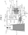
- the circulating reduction system 100 includes a reduction furnace 10, a first dehumidifier 20, a hydrogen gas supply apparatus 30, a catalytic apparatus 40, a second dehumidifier 50, a gas heating apparatus 60, and piping including first piping 81, second piping 82, third piping 83, fourth piping 84, fifth piping 85, sixth piping 86, seventh piping 87, and a switching valve 90.
- the reduction furnace 10 may be a smelting furnace, for example a blast furnace.
- a smelting furnace iron ore and coke are charged into the reduction furnace 10 from a furnace top 12, and high-temperature reducing gas is blown into the reduction furnace 10 from a tuyere 14 disposed at a bottom portion of the reduction furnace 10.
- the first piping 81 is piping that recovers exhaust gas generated in the reduction furnace 10 and containing CO 2 from the reduction furnace 10, and passes the exhaust gas through the piping system.
- the first piping 81 is connected at a start end to the reduction furnace 10 (as an example, to the furnace top 12) and at a terminal end to the catalytic apparatus 40.
- the hydrogen gas supply apparatus 30 is connected to a point along the first piping 81.
- the first dehumidifier 20 is disposed at a point along the first piping 81, upstream from the site where the hydrogen gas supply apparatus 30 is connected.
- the first piping 81 includes piping 81A extending from the reduction furnace 10 and connecting to the first dehumidifier 20, and piping 81B extending from the first dehumidifier 20 and connecting to the catalytic apparatus 40.
- upstream or downstream with respect to piping refers to gas flow direction in the piping.
- Exhaust gas discharged from the furnace top 12 of the reduction furnace 10 is dehumidified by the first dehumidifier 20 in the process of flowing through the first piping 81, and then hydrogen (H 2 ) gas is supplied from the hydrogen gas supply apparatus 30 to become hydrogen-added gas.
- Dehumidification is preferably carried out to suppress the water-gas shift reaction and promote the reverse water-gas shift reaction.
- the composition of the exhaust gas is not particularly limited, but typically has a composition consisting of CO 2 : 13 vol% to 24 vol%, CO: 21 vol% to 31 vol%, and H 2 : 3 vol% to 15 vol%, excluding water vapor, with the balance consisting of air-derived N 2 .
- the composition of the hydrogen-added gas is not particularly limited, but typically has a composition consisting of CO 2 : 13 vol% to 24 vol%, CO: 21 vol% to 31 vol%, and H 2 : 10 vol% to 30 vol%, excluding water vapor, with the balance consisting of air-derived N 2 .
- the hydrogen supplied from the hydrogen gas supply apparatus 30 is preferably green hydrogen obtained by water electrolysis using renewable energy, but until coke usage is decreased to zero by applying the circulating reduction system of the present disclosure to blast furnace operation, hydrogen purified from coke oven gas can be substituted.
- a de-duster (not illustrated) is preferably provided at a point along the first piping 81, upstream of the first dehumidifier 20 or downstream of the first dehumidifier 20 and upstream of the site where the hydrogen gas supply apparatus 30 is connected, to remove dust derived from raw material from the exhaust gas by applying dust removal treatment to the exhaust gas.
- the catalytic apparatus (reverse shift reformer) 40 includes a reaction chamber 42 to which the terminal end of the first piping 81 is connected and which contains catalyst for the reverse water-gas shift reaction, and a heating apparatus 44 that heats the reaction chamber 42.
- hydrogen-added gas introduced into the reaction chamber 42 from the first piping 81 comes into contact with the catalyst, and CO 2 in the hydrogen-added gas is converted to CO in a reverse water-gas shift reaction, resulting in CO-rich gas having increased CO concentration.
- the composition of the CO-rich gas after the reverse water-gas shift reaction is not particularly limited, but typically has a composition consisting of CO 2 : 6 vol% to 20 vol%, CO: 24 vol% to 40 vol%, and H 2 : 5 vol% to 24 vol% , excluding water vapor, with the balance consisting of air-derived N 2 .
- catalysts that can be used for the reverse water-gas shift reaction, including nickel-based and precious metal-based catalysts, any of which may be used according to the present disclosure.
- the temperature of the introduced hydrogen-added gas is preferably as high as possible in a temperature range where the catalyst is not easily degraded.
- the reaction chamber 42 is preferably heated by the heating apparatus 44 so that the temperature of the reaction gas (hydrogen-added gas) around the catalyst is 800 °C or more and 1200 °C or less.
- the second piping 82 is piping that extends from the catalytic apparatus 40 and is connected to the reduction furnace 10 (in one example, to the tuyere 14).
- the CO-rich gas is passed through the second piping and supplied (in one example, via the tuyere 14) to the inside of the reduction furnace 10 as reducing gas.
- the second dehumidifier 50 that removes water vapor from the CO-rich gas and the gas heating apparatus 60 that heats the CO-rich gas are preferably disposed at points along the second piping 82. In this case, the gas heating apparatus 60 is preferably disposed downstream of the second dehumidifier 50.
- the second piping 82 includes piping 82A extending from the catalytic apparatus 40 and connecting to the second dehumidifier 50, piping 82B extending from the second dehumidifier 50 and connecting to the gas heating apparatus 60, and piping 82C extending from the gas heating apparatus 60 and connecting to the reduction furnace 10 (in one example, to the tuyere 14).
- the CO-rich gas that has passed through the catalytic apparatus 40 is, in the process of flowing through the second piping 82, dehumidified by the second dehumidifier 50 then heated by the gas heating apparatus 60, and then blown into the reduction furnace 10 as reducing gas.
- the temperature of the CO-rich gas (reducing gas) blown into the reduction furnace 10 after the reaction with the catalyst is preferably adjusted by the gas heating apparatus 60.
- the temperature of the reducing gas blown into the reduction furnace 10 is preferably 900 °C or more.
- the temperature of the molten source of iron and slag formed in the lower region of the reduction furnace 10 needs to be maintained at 1650 °C or more.
- the reducing gas is preferably heated and blown in such that, when the coke input is up to about 50 % of that of a conventional blast furnace, the temperature of the reducing gas is 1200 °C or more, and when the coke input is less than 20 % than that of a conventional blast furnace, the temperature of the reducing gas is 1500 °C or more.
- the circulating reduction system 100 preferably includes the third piping 83 that branches off from the second piping 82, at a position upstream of the gas heating apparatus 60 and downstream of the second dehumidifier 50, and is connected to the gas heating apparatus 60.
- a portion of the CO-rich gas flowing through the second piping 82 is preferably supplied to the gas heating apparatus 60 as combustion gas via the third piping 83.
- oxygen-containing gas supplied to the gas heating apparatus 60 to burn the combustion gas is preferably oxygen gas (not containing nitrogen that is not consumed).
- the circulating reduction system 100 preferably includes the fourth piping 84 extending from the gas heating apparatus 60 and connected to a point along the first piping 81.
- the combustion exhaust gas generated from the gas heating apparatus 60 is preferably merged with the exhaust gas in the first piping 81 via the fourth piping 84, and reused.
- the fourth piping 84 is preferably connected at a point along the first piping 81, upstream of the first dehumidifier 20.
- the reducing gas and the hydrogen-added gas can also be preheated.
- the gas heating apparatus 60 that is an indirect heating type, as illustrated in FIG. 1 , cannot raise the reducing gas to the desired temperature, some of the CO and H 2 contained in the reducing gas may be burned directly by adding oxygen from near a leading end of the gas heating apparatus 60. Further, when oxygen-enriched air produced by cryogenic separation or the like is used as hot blast blown into the reduction furnace 10 when starting up in the blast furnace mode, the heat load of the gas heating apparatus 60 that is lost to nitrogen heating is decreased, making raising the temperature of the reducing gas easier.
- the circulating reduction system 100 preferably includes the fifth piping 85 branching off from the second piping 82 and connected to the heating apparatus 44 of the catalytic apparatus 40.
- the fifth piping 85 preferably branches off from a point along the second piping 82, at a position upstream from the gas heating apparatus 60 and downstream from the second dehumidifier 50.
- a portion of the CO-rich gas is preferably supplied as combustion gas to the heating apparatus 44 via the fifth piping 85.
- oxygen-containing gas supplied to the heating apparatus 44 to burn the combustion gas is preferably oxygen gas (not containing nitrogen that is not consumed).
- the circulating reduction system 100 preferably includes the sixth piping 86 extending from the heating apparatus 44 and connected to a point along the first piping 81.
- Combustion exhaust gas generated from the heating apparatus 44 is preferably merged with the exhaust gas in the first piping 81 via the sixth piping 86, and reused.
- an upstream portion 86A of the sixth piping 86 is connected to a point along the fourth piping 84, which is a flow path of fuel exhaust gas from the gas heating apparatus 60, and therefore a downstream portion 86B of the sixth piping 86 also serves as a downstream portion 84B of the fourth piping 84.
- the present disclosure is not limited to this example, and the sixth piping 86 may of course be directly connected to the first piping 81 independently of the fourth piping 84.
- the combustion exhaust gas from the heating apparatus 44 can also preheat the hydrogen-added gas when heat exchanged with the hydrogen-added gas piping between the hydrogen gas supply apparatus 30 and the catalytic apparatus 40 and then merge with the exhaust gas in the first piping 81 upstream of the first dehumidifier 20.
- the processes of reducing iron ore by blowing in reducing gas, recovering exhaust gas from the reduction furnace, removing dust and dehumidifying exhaust gas (optional processes), adding hydrogen gas to the exhaust gas, generating CO-rich gas from the hydrogen-added gas by the reverse water-gas shift reaction, dehumidifying the CO-rich gas (optional process), heating the CO-rich gas (optional process), and blowing the CO-rich gas as reducing gas are repeated to realize a circulation process in which exhaust gas from the reduction furnace 10 is reused in a closed circulation system.
- the unconverted CO 2 that remains in the CO-rich gas to be used as the reducing gas will eventually become a CO source during the circulation process, and therefore does not need to be separated from the reducing gas. That is, in the present embodiment, it is important that no separation apparatus is disposed at any point along the first piping 81 nor the second piping 82 to separate and either recover or remove a specific gas component other than water vapor from gas passing through the first piping 81 or gas passing through the second piping 82. According to the present embodiment, no new separation or concentration process is required other than dust removal and dehumidification, to which existing technology can be applied, and therefore reducing gas circulation efficiency is high.
- the reverse water-gas shift reaction is used that converts CO 2 to CO with an equimolar amount of hydrogen, and therefore the amount of hydrogen per CO 2 can be suppressed to about 1/4 of that of the conventional reduction method described above, which uses methane produced by a methanation reaction as the reductant, which requires four times as much hydrogen as CO 2 in moles.
- reducing gas mainly composed of CO converted from exhaust gas can be fed into the reduction furnace 10 at high temperature, and impurities in iron ore can be separated from hot metal as molten slag, and therefore low-grade powdered ore or fine ore, which are cost effective and easily procured, can be used as pellets or sintered ore, as in a typical blast furnace.
- a surplus of CO-rich gas (according to the present embodiment, a remainder of the CO-rich gas used as reducing gas, combustion gas for the gas heating apparatus 60, and combustion gas for the heating apparatus 44) can be recovered. That is, the circulating reduction system 100 includes the switching valve 90 disposed at a point along the second piping 82, and the seventh piping 87 extending from the switching valve 90, through which a portion of the CO-rich gas can be recovered.
- the recovered CO-rich gas may be used as synthesis gas, for example, as a raw material for organic compounds.
- the CO 2 -rich exhaust gas discharged from the reduction furnace 10 is converted to CO-rich reducing gas and recycled, and therefore the surplus of CO-rich gas can be effectively utilized as synthesis gas in the organic chemical industry and the like, thereby reducing CO 2 emissions into air to a zero level.
- the molten slag separated from the hot metal is slowly cooled in a mold to solidified slag, which is then crushed into crushed slag, which can be reused as gas permeable material.
- the pig iron can be returned to the reduction furnace as a source of iron via the gas permeable material.
- the molten slag is automatically discharged onto the surface of the hot metal due to the difference in specific gravity, and therefore recycling has almost no adverse effect on the quality of the hot metal.
- the recycled molten slag has equivalent quality as regular blast-furnace slag, and can be used industrially as a raw material for blast-furnace cement and the like.
- a circulating reduction system 200 according to another embodiment of the present disclosure is described below, with reference to FIG. 2 .
- the circulating reduction system 200 has the same configuration as the circulating reduction system 100, except that the second dehumidifier 50 is not included and instead a third dehumidifier 70 is included, disposed at a point along the seventh piping 87. That is, according to the present disclosure, the second dehumidifier 50 is not an essential component.
- the third dehumidifier 70 is preferably used to remove water vapor from the CO-rich gas passing through the seventh piping 87.
- the reduction furnace 10 is a smelting furnace such as a blast furnace and the material to be reduced is iron ore.
- the reduction furnace 10 may be a solid reduction furnace.
- the material to be reduced is not limited to iron ore as long as it is an oxide.
- the material to be reduced may be manganese ore, the raw material for ferromanganese and silicomanganese.
- the iron ore reduction method uses the circulating reduction system 100, 200 described above to reduce iron ore as an oxide by recycling CO-rich gas obtained by reforming exhaust gas as reducing gas. This allows the CO-rich gas obtained by reforming the exhaust gas containing CO 2 generated from the reduction furnace 10 to be efficiently recycled as reducing gas for the reduction of iron ore.
- the reduction method according to the present embodiment realizes an efficient reduction process in which the exhaust gas from the reduction furnace 10 can be recycled as a starting material for reductant, and therefore can significantly decrease CO 2 generation. Further, the amount of fossil fuel-derived reductant such as coke conventionally used in the iron ore reduction process can be drastically decreased.
- the smelting furnace operation method is carried out using the circulating reduction system 100, 200 described above. It is essential that, from the furnace top of the reduction furnace (smelting furnace) 10, (I) at least one of iron ore selected from sintered ore, lump ore, iron ore pellets, and fine ore (source of iron), and (II) gas permeable material consisting of crushed slag obtained by crushing solidified slag obtained by slow cooling molten slag discharged from the bottom of the smelting furnace, or a mixture of the crushed slag and coke, are alternately charged in layers to secure gas permeability of the reducing gas in the furnace.
- reducing gas and air are supplied to the inside of the smelting furnace as blowing gas from the tuyere 14. At this time, it is preferable to gradually increase a ratio of the crushed slag to the coke in the gas permeable material and a ratio of the reducing gas to the air in the blown gas to gradually decrease the amount of the coke.
- reduced iron in the form of hot metal can be obtained using low-grade powdered ore or fine ore, which are low cost and easy to procure, and therefore a conventional integrated steelmaking process can be used directly for the next process and beyond.
- the degree of gas permeability of the smelting furnace can be adjusted by the particle size of the crushed slag, and gas permeability is even easier to secure when, for example, the slow-cooled slag is cast in a way that adds ventilation holes. There is no particular problem in using typical blast-furnace slag as gas permeable material.
- the amount of molten slag generated in the circulation-type smelting furnace 100, 200 is greater than in a typical blast furnace because slag that is re-charged from the furnace top 12 is re-melted after the cohesive zone. Further, the more slag that is added, the more heat is lost as slag melting heat. Therefore, when starting up operation in the blast furnace mode, the layer thickness ratio of the source of iron layer and the gas permeable layer is preferably adjusted in advance so that the source of iron layer is richer than in a typical blast furnace.
- FIG. 3 An equilibrium calculation model of the circulating reduction system according to Inventive Example 1 is illustrated in FIG. 3 .
- the reduction furnace 10 containing 25 mol of iron oxide (III) (Fe 2 O 3 ) is connected to a reverse shift reformer serving as the catalytic apparatus 40 (hereinafter simply referred to as "reformer 40") containing a mixed gas equivalent to a total of 100 mol of blast furnace exhaust gas, consisting of CO: 22 mol, CO 2 : 22.8 mol, H 2 : 4.2 mol, and N 2 : 51 mol.
- the first dehumidifier 20 is disposed at the inlet of the reformer
- the second dehumidifier 50 is disposed at the outlet of the reformer
- a hydrogen gas supply apparatus 30 is disposed between the first dehumidifier and the reformer to maintain the H 2 mole number in the reformer at 22.8 mol (corresponding to the CO 2 concentration in blast furnace exhaust gas). Assuming that no gases other than H 2 supplied from the hydrogen gas supply apparatus and H 2 O removed by the first dehumidifier and the second dehumidifier enter or leave the reduction furnace and the reformer, all H 2 O is generated from consumed H 2 and therefore the total number of moles of mixed gas circulating through the reformer and the reduction furnace does not change.
- the temperature in the reduction furnace and the reformer are both maintained at 900 °C by externally supplied heat.
- Actual gas circulation between the reduction furnace and the reformer requires a gas transport system, but for the purpose of proof of principle, energy consumed by this is ignored.
- energy consumed to drive the first dehumidifier, the second dehumidifier, and the hydrogen gas supply apparatus is also ignored.
- the reverse water-gas shift reaction in the reformer may not reach equilibrium and therefore may be dependent on the performance of the catalyst used, but is assumed to reach equilibrium.
- a repeated circulation process is considered in which the reducing gas generated when hydrogen-added gas reaches a steady state in the reformer is all sent to the reduction furnace, and the gas in the reduction furnace when the reduction reaction reaches a steady state is extracted as exhaust gas, to which hydrogen is added up to a certain level to produce hydrogen-added gas again, with this cycle being considered as one cycle.
- Equilibrium of gas components and a source of iron in the reformer and in the reduction furnace, which occur at each cycle of feeding the reducing gas from the reformer to the reduction furnace, were calculated using the thermodynamic equilibrium calculation software & thermodynamic database FactSage 8.1 from Research Center of Computational Mechanics, Inc. The results are illustrated in FIG. 4 . Compounds formed in the reformer and the reduction furnace include methane and the like, but trace components of 0.005 mol or less were ignored.
- the reduction of the source of iron proceeds by CO supplied from the reformer and excess H 2 that was not consumed in the reverse water-gas shift reaction.
- the solid-phase Fe 2 O 3 charged as a source of iron is converted into twice the molar amount of FeO (solid phase) in the first cycle, and from the second cycle onwards, the FeO is gradually reduced and converted to ⁇ -Fe (solid phase), with the reduction being completed in the seventh cycle.
- the main reduction reaction being from FeO to ⁇ -Fe is consistent with the findings known from blast furnaces.
- the amount of H 2 consumed in the reduction of this source of iron is 89 mol.
- FIG. 5 An equilibrium calculation model of the circulating reduction system according to Inventive Example 2 is illustrated in FIG. 5 . This is the same as the equilibrium calculation model of the circulating reduction system according to Inventive Example 1 illustrated in FIG. 3 , except that there is no second dehumidifier on the outlet side of the reformer.
- the calculation conditions are the same as in Inventive Example 1, and equilibrium of gas components and source of iron in the reformer and in the reduction furnace were calculated. The results are illustrated in FIG. 6 .
- the solid-phase FeaOs charged as a source of iron is converted into twice the molar amount of FeO (solid phase) in the first cycle, and from the third cycle onwards, the FeO is gradually reduced and converted to ⁇ -Fe (solid phase), with the reduction being completed in the ninth cycle.
- the main reduction reaction being from FeO to ⁇ -Fe is consistent with the findings known from blast furnaces.
- the amount of H 2 consumed in the reduction of this source of iron is 85 mol.
- FIG. 7 An equilibrium calculation model of a circulating reduction system according to a comparative example is illustrated in FIG. 7 . This is the same as the equilibrium calculation model of the circulating reduction system according to Inventive Example 1 illustrated in FIG. 3 , except that there is no reformer or second dehumidifier on the outlet side of the reformer.
- the calculation conditions are the same as in Inventive Example 1, and equilibrium of gas components and source of iron in the reformer and in the reduction furnace were calculated. The results are illustrated in FIG. 8 .
- the reduction of the source of iron proceeds only with H 2 , which is fed directly into the reduction furnace from the hydrogen gas supply apparatus.
- the 25 mol of Fe 2 O 3 (solid phase) charged as the source of iron is converted to 8.2 mol of Fe 3 O 4 (solid phase) and 22.5 mol of FeO (solid phase) in the first cycle, and from the second cycle onwards, the FeO is gradually reduced and converted to ⁇ -Fe (solid phase), with the reduction being completed in the ninth cycle, as in Inventive Example 2.
- the main reduction reaction being from FeO to ⁇ -Fe is the same as in Inventive Examples 1 and 2.
- the amount of H 2 consumed in the reduction of this source of iron is 75 mol, 10 mol less than in Inventive Example 2.
- the major difference between Inventive Examples 1 and 2 and the comparative example is the amount of heat absorbed in the reduction furnace.
- the total reaction heat (heat absorption) in the reduction furnace calculated from the reaction heat for each reaction by FactSage 8.1 is illustrated in FIG. 9 and FIG. 10 .
- the direct reduction of the source of iron by H 2 is an endothermic reaction, except for the reaction from Fe 2 O 3 to Fe 3 O 4 , which is completed early in the process.
- the amount of heat generated from CO reduction compensates for the heat absorption due to H 2 reduction, and therefore the total heat absorption can be greatly decreased (see FIG. 9 ).
- the amount of heat generated by CO reduction exceeds the amount of heat absorbed by H 2 reduction in the FeO reduction range, and therefore the reduction temperature of FeO is spontaneously maintained at a high temperature (see FIG. 9 ).
- the FeO reduction phase becomes even longer as the amount of source of iron input increases.
- the amount of H 2 supplied to the reformer to maximize the amount of heat generated in the reduction range of FeO is expected to be about the same as the molar amount of CO 2 in the exhaust gas.
- the reduction rate is also expected to decrease.
- the amount of H 2 supplied is adjusted based on the balance between the temperature in the reduction furnace and the reduction rate.
- FIG. 11 The configuration of the experimental circulating reduction system according to Inventive Example 3 is illustrated in FIG. 11 .
- 2.2 kg of coke pulverized to approximately 5 mm and 5.0 kg of lump ore pulverized to approximately 3 mm were alternately layered on a tungsten mesh partitioning the furnace bottom of a BF simulator (hereinafter also referred to as "reduction furnace 10"), which was an experimental reducing furnace installed on a weight scale, to form a raw material block A.
- a BF simulator hereinafter also referred to as "reduction furnace 10”
- a raw material block B was formed on top of the raw material block A, by alternately layering a uniform mixture of 1.1 kg of the coke described above and 2.8 kg of slow-cooled blast furnace slag pulverized to approximately 5 mm, and 5.0 kg of lump ore pulverized to approximately 3 mm.
- Exhaust gas discharged from the furnace top after passing through a de-duster, the dehumidifier 20, a first electric tube furnace 40, a dehumidifier, a second electric tube furnace 40, the dehumidifier 50, and a regenerative gas heating furnace 60, was connected via a switching valve 91 to an exhaust gas processor on one side and a nozzle 92 at a bottom portion of the reduction furnace on the other side.
- the two electric tube furnaces 40 were ceramic electric tube furnaces in which a quartz reaction tube holding 51 g of platinum catalyst is set in the center.
- nozzle 96 On the opposite side of the nozzle 92 at the bottom portion of the reduction furnace 10 was a nozzle 96 that fed 2.3% oxygen-enriched air via a regenerative gas heating furnace 95.
- the flow rate of air introduced through the nozzle 96 was controlled by a mass flow controller (MFC) 97.
- MFC mass flow controller
- purge nitrogen gas piping was connected between the dehumidifier 20 and the switching valve 93 via a switching valve 98.
- the exhaust gas was separated from the reduction furnace 10 by setting the switching valve 91 to the exhaust gas processor side. Air heated to 1200 °C by MFC 97 was then introduced into the reduction furnace 10 at a flow rate of 17 L/min from the nozzle 96 of the reduction furnace 10. Both of the two electric tube furnaces 40 were set to reach an internal temperature of 800 °C using thermocouples (TC) located around the catalyst.
- TC thermocouples
- compositions of the exhaust gas produced by the reduction of lump ore in the raw material block A and the mixed gas after passing through the second electric tube furnace 40 are listed in Table 1. It can be seen that, after passing through the second electric tube furnace 40, CO increased by 2.7 % and CO 2 and H 2 decreased by 2.7 % each due to the reverse water-gas shift reaction caused by excess H 2 in the exhaust gas.
- the air flow rate introduced through the nozzle 96 was changed to 8.5 L/min at the MFC 97.
- the switching valve 93 was switched to the hydrogen piping 30 side to introduce hydrogen gas, and the MFC 94 was used to adjust the H 2 concentration in the mixed gas to 22.8 % (the same as the CO 2 concentration in the initial exhaust gas) before entering the first electric tube furnace 40.
- the switching valve 91 was then switched to the reduction furnace 10 side, and reducing gas was introduced through the nozzle 92.
- the total consumption of coke in the raw material block A was determined from the weight change of the reduction furnace 10.
- FIG. 12 The configuration of the experimental circulating reduction system according to Inventive Example 4 is illustrated in FIG. 12 . This is the same as the circulating reduction system of Inventive Example 3 illustrated in FIG. 11 , except that the electric tube furnace 40 was a single unit and a dehumidifier was not disposed downstream of the electric tube furnace 40.
- the electric tube furnace 40 was set to an internal temperature of 900 °C using a thermocouple (TC) around the catalyst. Other conditions were the same as in Inventive Example 3.
- TC thermocouple
- compositions of the exhaust gas produced by the reduction of lump ore in the raw material block A and the mixed gas after passing through the electric tube furnace 40 are listed in Table 1. It can be seen that, after passing through the electric tube furnace 40, CO increased by 1.8 % and CO 2 and H 2 decreased by 1.8 % each due to the reverse water-gas shift reaction caused by excess H 2 in the exhaust gas.
Landscapes
- Engineering & Computer Science (AREA)
- Chemical & Material Sciences (AREA)
- Manufacturing & Machinery (AREA)
- Materials Engineering (AREA)
- Metallurgy (AREA)
- Organic Chemistry (AREA)
- Waste-Gas Treatment And Other Accessory Devices For Furnaces (AREA)
- Manufacture Of Iron (AREA)
Applications Claiming Priority (2)
| Application Number | Priority Date | Filing Date | Title |
|---|---|---|---|
| JP2022137231 | 2022-08-30 | ||
| PCT/JP2023/030590 WO2024048423A1 (ja) | 2022-08-30 | 2023-08-24 | 循環型還元システム、鉄鉱石の還元方法、及び溶鉱炉の操業方法 |
Publications (2)
| Publication Number | Publication Date |
|---|---|
| EP4509617A1 true EP4509617A1 (de) | 2025-02-19 |
| EP4509617A4 EP4509617A4 (de) | 2025-06-11 |
Family
ID=90099760
Family Applications (1)
| Application Number | Title | Priority Date | Filing Date |
|---|---|---|---|
| EP23860186.8A Pending EP4509617A4 (de) | 2022-08-30 | 2023-08-24 | Zirkulierendes reduktionssystem, eisenerzreduktionsverfahren und hochofenbetriebsverfahren |
Country Status (6)
| Country | Link |
|---|---|
| EP (1) | EP4509617A4 (de) |
| JP (1) | JP7669596B2 (de) |
| KR (1) | KR102891619B1 (de) |
| CN (1) | CN119487216A (de) |
| TW (1) | TWI886552B (de) |
| WO (1) | WO2024048423A1 (de) |
Families Citing this family (4)
| Publication number | Priority date | Publication date | Assignee | Title |
|---|---|---|---|---|
| WO2025215401A1 (en) * | 2024-04-11 | 2025-10-16 | Arcelormittal | Ironmaking method and associated plant |
| TWI889598B (zh) * | 2024-11-14 | 2025-07-01 | 中國鋼鐵股份有限公司 | 鼓風嘴結構及使用鼓風嘴結構進行噴吹操作的方法 |
| US12595966B1 (en) | 2025-01-13 | 2026-04-07 | Schlumberger Technology Corporation | Recycling carbon in blast furnace gas emissions |
| CN121538365A (zh) * | 2026-01-20 | 2026-02-17 | 安徽工业大学 | 一种co2介导的间接氢冶金高炉冶炼工艺 |
Family Cites Families (13)
| Publication number | Priority date | Publication date | Assignee | Title |
|---|---|---|---|---|
| US4265868A (en) * | 1978-02-08 | 1981-05-05 | Koppers Company, Inc. | Production of carbon monoxide by the gasification of carbonaceous materials |
| JPH09100108A (ja) * | 1995-10-05 | 1997-04-15 | Cosmo Eng Kk | 一酸化炭素ガスの製造方法 |
| JP5640786B2 (ja) | 2010-03-30 | 2014-12-17 | Jfeスチール株式会社 | 高炉又は製鉄所の操業方法 |
| JP5594025B2 (ja) * | 2010-09-29 | 2014-09-24 | Jfeスチール株式会社 | 高炉用原料及びその製造方法 |
| DE102013009993A1 (de) | 2013-06-14 | 2014-12-18 | CCP Technology GmbH | Hochofen und Verfahren zum Betrieb eines Hochofens |
| JP2017088912A (ja) | 2015-11-04 | 2017-05-25 | 株式会社神戸製鋼所 | 還元鉄の製造方法 |
| RU2726175C1 (ru) * | 2016-09-20 | 2020-07-09 | Мидрэкс Текнолоджиз, Инк. | Способы и системы для повышения содержания углерода в губчатом железе в восстановительной печи |
| CN106399617A (zh) | 2016-12-16 | 2017-02-15 | 江苏省冶金设计院有限公司 | 一种气基竖炉直接还原炼铁的系统及方法 |
| CN111171848B (zh) * | 2020-01-21 | 2021-05-28 | 太原理工大学 | 一种生产高纯钢铁和氢气的系统及方法 |
| WO2021220555A1 (ja) | 2020-04-27 | 2021-11-04 | Jfeスチール株式会社 | 製鉄設備および還元鉄の製造方法 |
| KR20220158079A (ko) * | 2020-05-28 | 2022-11-29 | 닛폰세이테츠 가부시키가이샤 | 환원철의 제조 방법 |
| WO2022029886A1 (ja) * | 2020-08-04 | 2022-02-10 | 積水化学工業株式会社 | ガス製造装置、ガス製造システム、製鉄システム、化学品製造システムおよびガス製造方法 |
| CN114807485A (zh) * | 2022-03-09 | 2022-07-29 | 中冶赛迪工程技术股份有限公司 | 一种生产直接还原铁的煤气处理方法及系统 |
-
2023
- 2023-08-24 CN CN202380053527.8A patent/CN119487216A/zh active Pending
- 2023-08-24 KR KR1020247038919A patent/KR102891619B1/ko active Active
- 2023-08-24 EP EP23860186.8A patent/EP4509617A4/de active Pending
- 2023-08-24 WO PCT/JP2023/030590 patent/WO2024048423A1/ja not_active Ceased
- 2023-08-24 JP JP2024544187A patent/JP7669596B2/ja active Active
- 2023-08-28 TW TW112132363A patent/TWI886552B/zh active
Also Published As
| Publication number | Publication date |
|---|---|
| CN119487216A (zh) | 2025-02-18 |
| JP7669596B2 (ja) | 2025-04-28 |
| TWI886552B (zh) | 2025-06-11 |
| EP4509617A4 (de) | 2025-06-11 |
| KR20250004321A (ko) | 2025-01-07 |
| TW202426662A (zh) | 2024-07-01 |
| WO2024048423A1 (ja) | 2024-03-07 |
| JPWO2024048423A1 (de) | 2024-03-07 |
| KR102891619B1 (ko) | 2025-11-26 |
Similar Documents
| Publication | Publication Date | Title |
|---|---|---|
| JP7669596B2 (ja) | 循環型還元システム、鉄鉱石の還元方法、及び溶鉱炉の操業方法 | |
| JP2025102916A (ja) | 放出を減らした鋼または溶鉄含有材料を生産する方法及びシステム | |
| US20230038218A1 (en) | Facility and method for production of direct reduced iron | |
| EP4402293B1 (de) | Verfahren zur herstellung von direkt reduziertem eisen für eine eisen- und stahlherstellungsanlage | |
| JP7670182B2 (ja) | 還元鉄の製造方法 | |
| EP3868899B1 (de) | Vorrichtung zur herstellung von eisenschmelze vom kohlendioxidemissionsreduktionstyp und verfahren zu ihrer herstellung davon | |
| JP2025510647A (ja) | 還元金属材料を製造するための方法及び構成 | |
| JP7605376B2 (ja) | 還元鉄の製造方法 | |
| JP6137087B2 (ja) | 焼結鉱の製造方法 | |
| JP7736187B2 (ja) | 還元鉄の製造方法 | |
| Cavaliere | Hydrogen Ironmaking | |
| JP7605375B2 (ja) | 還元鉄の製造方法 | |
| JP7740549B2 (ja) | 還元鉄の製造方法 | |
| JP7718901B2 (ja) | 極低炭素フェロマンガンの製造方法及びその製造装置並びにマンガン系合金の製造方法及びその製造装置 | |
| WO2025008143A1 (en) | Method for producing direct reduced iron | |
| KR20240018212A (ko) | 용철 제조 설비 및 용철 제조 방법 | |
| WO2025021365A1 (en) | Method for producing direct reduced iron | |
| WO2024165142A1 (en) | Process of direct reduction of iron ores by means of synthesis gas produced with catalytic partial oxidation | |
| JPH11502571A (ja) | 直接の製鉄および製鋼 | |
| IT202300020244A1 (it) | Processo di riduzione di minerale di ferro alimentato con idrogeno | |
| JPS6220808A (ja) | 2段吹込みによる鉄鉱石の溶融還元製鉄方法 | |
| JPS59173210A (ja) | 粉状原燃料使用シヤフト炉製銑法 | |
| JPS62230925A (ja) | 溶融還元鉄の製造方法 |
Legal Events
| Date | Code | Title | Description |
|---|---|---|---|
| STAA | Information on the status of an ep patent application or granted ep patent |
Free format text: STATUS: THE INTERNATIONAL PUBLICATION HAS BEEN MADE |
|
| PUAI | Public reference made under article 153(3) epc to a published international application that has entered the european phase |
Free format text: ORIGINAL CODE: 0009012 |
|
| STAA | Information on the status of an ep patent application or granted ep patent |
Free format text: STATUS: REQUEST FOR EXAMINATION WAS MADE |
|
| 17P | Request for examination filed |
Effective date: 20241113 |
|
| AK | Designated contracting states |
Kind code of ref document: A1 Designated state(s): AL AT BE BG CH CY CZ DE DK EE ES FI FR GB GR HR HU IE IS IT LI LT LU LV MC ME MK MT NL NO PL PT RO RS SE SI SK SM TR |
|
| A4 | Supplementary search report drawn up and despatched |
Effective date: 20250514 |
|
| RIC1 | Information provided on ipc code assigned before grant |
Ipc: C21B 13/00 20060101ALI20250508BHEP Ipc: C21B 7/00 20060101ALI20250508BHEP Ipc: C21B 11/00 20060101ALI20250508BHEP Ipc: C21B 5/00 20060101ALI20250508BHEP Ipc: C21B 5/06 20060101AFI20250508BHEP |
|
| DAV | Request for validation of the european patent (deleted) | ||
| DAX | Request for extension of the european patent (deleted) | ||
| STAA | Information on the status of an ep patent application or granted ep patent |
Free format text: STATUS: EXAMINATION IS IN PROGRESS |
|
| 17Q | First examination report despatched |
Effective date: 20251218 |