EP4509657A1 - Appareil de fraisage ou de coupe de joints doté d'une traction à embrayage magnétique et son procédé de commande - Google Patents
Appareil de fraisage ou de coupe de joints doté d'une traction à embrayage magnétique et son procédé de commande Download PDFInfo
- Publication number
- EP4509657A1 EP4509657A1 EP24020266.3A EP24020266A EP4509657A1 EP 4509657 A1 EP4509657 A1 EP 4509657A1 EP 24020266 A EP24020266 A EP 24020266A EP 4509657 A1 EP4509657 A1 EP 4509657A1
- Authority
- EP
- European Patent Office
- Prior art keywords
- milling
- joint
- cutting device
- combustion engine
- drive
- Prior art date
- Legal status (The legal status is an assumption and is not a legal conclusion. Google has not performed a legal analysis and makes no representation as to the accuracy of the status listed.)
- Granted
Links
Images







Classifications
-
- B—PERFORMING OPERATIONS; TRANSPORTING
- B28—WORKING CEMENT, CLAY, OR STONE
- B28D—WORKING STONE OR STONE-LIKE MATERIALS
- B28D1/00—Working stone or stone-like materials, e.g. brick, concrete or glass, not provided for elsewhere; Machines, devices, tools therefor
- B28D1/18—Working stone or stone-like materials, e.g. brick, concrete or glass, not provided for elsewhere; Machines, devices, tools therefor by milling, e.g. channelling by means of milling tools
-
- B—PERFORMING OPERATIONS; TRANSPORTING
- B28—WORKING CEMENT, CLAY, OR STONE
- B28D—WORKING STONE OR STONE-LIKE MATERIALS
- B28D1/00—Working stone or stone-like materials, e.g. brick, concrete or glass, not provided for elsewhere; Machines, devices, tools therefor
- B28D1/02—Working stone or stone-like materials, e.g. brick, concrete or glass, not provided for elsewhere; Machines, devices, tools therefor by sawing
- B28D1/04—Working stone or stone-like materials, e.g. brick, concrete or glass, not provided for elsewhere; Machines, devices, tools therefor by sawing with circular or cylindrical saw-blades or saw-discs
- B28D1/045—Sawing grooves in walls; sawing stones from rocks; sawing machines movable on the stones to be cut
-
- E—FIXED CONSTRUCTIONS
- E01—CONSTRUCTION OF ROADS, RAILWAYS, OR BRIDGES
- E01C—CONSTRUCTION OF, OR SURFACES FOR, ROADS, SPORTS GROUNDS, OR THE LIKE; MACHINES OR AUXILIARY TOOLS FOR CONSTRUCTION OR REPAIR
- E01C23/00—Auxiliary devices or arrangements for constructing, repairing, reconditioning, or taking-up road or like surfaces
- E01C23/06—Devices or arrangements for working the finished surface; Devices for repairing or reconditioning the surface of damaged paving; Recycling in place or on the road
- E01C23/09—Devices or arrangements for working the finished surface; Devices for repairing or reconditioning the surface of damaged paving; Recycling in place or on the road for forming cuts, grooves, or recesses, e.g. for making joints or channels for markings, for cutting-out sections to be removed; for cleaning, treating, or filling cuts, grooves, recesses, or fissures; for trimming paving edges
- E01C23/0906—Devices or arrangements for working the finished surface; Devices for repairing or reconditioning the surface of damaged paving; Recycling in place or on the road for forming cuts, grooves, or recesses, e.g. for making joints or channels for markings, for cutting-out sections to be removed; for cleaning, treating, or filling cuts, grooves, recesses, or fissures; for trimming paving edges for forming, opening-out, cleaning, drying or heating cuts, grooves, recesses or, excluding forming, cracks, e.g. cleaning by sand-blasting or air-jet ; for trimming paving edges
- E01C23/0926—Devices or arrangements for working the finished surface; Devices for repairing or reconditioning the surface of damaged paving; Recycling in place or on the road for forming cuts, grooves, or recesses, e.g. for making joints or channels for markings, for cutting-out sections to be removed; for cleaning, treating, or filling cuts, grooves, recesses, or fissures; for trimming paving edges for forming, opening-out, cleaning, drying or heating cuts, grooves, recesses or, excluding forming, cracks, e.g. cleaning by sand-blasting or air-jet ; for trimming paving edges with power-driven tools, e.g. vibrated, percussive cutters
- E01C23/0933—Devices or arrangements for working the finished surface; Devices for repairing or reconditioning the surface of damaged paving; Recycling in place or on the road for forming cuts, grooves, or recesses, e.g. for making joints or channels for markings, for cutting-out sections to be removed; for cleaning, treating, or filling cuts, grooves, recesses, or fissures; for trimming paving edges for forming, opening-out, cleaning, drying or heating cuts, grooves, recesses or, excluding forming, cracks, e.g. cleaning by sand-blasting or air-jet ; for trimming paving edges with power-driven tools, e.g. vibrated, percussive cutters rotary, e.g. circular-saw joint cutters
-
- B—PERFORMING OPERATIONS; TRANSPORTING
- B28—WORKING CEMENT, CLAY, OR STONE
- B28D—WORKING STONE OR STONE-LIKE MATERIALS
- B28D7/00—Accessories specially adapted for use with machines or devices of the preceding groups
- B28D7/02—Accessories specially adapted for use with machines or devices of the preceding groups for removing or laying dust, e.g. by spraying liquids; for cooling work
-
- E—FIXED CONSTRUCTIONS
- E01—CONSTRUCTION OF ROADS, RAILWAYS, OR BRIDGES
- E01C—CONSTRUCTION OF, OR SURFACES FOR, ROADS, SPORTS GROUNDS, OR THE LIKE; MACHINES OR AUXILIARY TOOLS FOR CONSTRUCTION OR REPAIR
- E01C2301/00—Machine characteristics, parts or accessories not otherwise provided for
- E01C2301/50—Methods or devices for preventing dust by spraying or sucking
Definitions
- the invention relates to a joint milling or cutting device with a travel drive with magnetic coupling according to patent claim 1 and according to patent claim 14 to a method for controlling the same.
- Joint cutting machines are generally operated at a higher speed than joint milling machines or have a saw blade with a large diameter; they usually work in a straight line.
- the milling disc enables both wide and narrow millings, which can be straight or curved as desired.
- a joint milling or cutting device with a two-axle carriage on which the necessary equipment, such as an internal combustion engine with a reduction gear to drive the milling disc or saw blade and, if necessary, a cooling water tank and/or vacuum cleaner, is arranged and with a device for adjusting the cutting depth of the milling disc or saw blade.
- An adjusting lever is provided for adjusting the cutting depth, which allows the wheel or both wheels of an axle to pivot relative to the carriage about a transverse axis fixed to the carriage.
- a spring is suspended between the carriage and the adjusting lever and is dimensioned such that it lifts the carriage and thus the milling disc or saw blade upwards out of the joint.
- the DE 295 11 771 U1 A joint milling, joint plow or brushing device with a three-axle carriage is known, which has drive wheels with a drive axle, a running wheel with a rigid axle, a swiveling steering wheel and a tool arranged behind the wheels, for example a milling disk.
- the milling disk can be guided under visual control in the cracks in the road surface and the cutting depth of the tool is set on the device using the guide bars, with fine adjustment being made using the height-adjustable running wheel.
- the drive wheels are arranged in such a way that when the operator lets go of the guide bars, the greater weight of the motor causes the carriage to tip forwards onto the running wheels and the steering wheel. This lifts the drive wheels off the road surface and the device stops and can then be moved back and forth more quickly by hand.
- the DE 299 08 397 U1 a hand-held device for milling pothole edges on asphalt surfaces and for milling off road markings.
- two wheels are pivotally mounted on the chassis of the device.
- the two wheels are attached to a lever, which is mounted on the chassis by a joint and is pulled upwards by two springs that are attached elsewhere on the chassis.
- the guide rod which is movably connected to the chassis, is pressed downwards, the milling drum is pressed into the asphalt.
- the springs immediately lift the milling drum out of the asphalt.
- the guide rod is connected to the lever arms in a joint-like manner with two levers.
- the milling tool, to which a gear is attached, is driven by a chain that is driven by a motor on the device with a reduction gear.
- the DE 44 08 396 A1 a joint milling machine with a rotating and motor-driven milling blade, which is attached to a support frame with a chassis and is height-adjustable, is known.
- a self-propelled drive and a guide head are provided, which is designed to permanently scan a joint to be milled ahead of the milling blade and to guide the joint milling machine along the joint.
- the DE 298 20 188 U1 A movable joint cutter, in particular for making cuts in road surfaces or similar surfaces made of asphalt, concrete or comparable building materials, is known, which has a chassis frame with front and rear wheels, at least one sawing device which has a rotating saw blade which can be lowered into the working position via an adjustment device, wherein the saw blade can be driven by a drive motor.
- the front wheels and the rear wheels are steerable, wherein the steering movement can be transmitted via a steering rod connected to the wheels.
- the DE 203 12 712 U1 A suction device for a crack milling machine is known in which the milling material is sucked out immediately before and after the milling machine using suction funnels and suction hoses, the coarse milling material is separated in a suction container with a cyclone and the remaining fine milling material is separated in a subsequent fine filter system with three flat filters arranged one behind the other and a subsequent settling chamber for dust separation.
- two suction hoses are arranged in front of the milling machine and one suction hose is arranged after the milling machine.
- the overall suction is operated with three suction motors and after the milling work is finished, the collected material is emptied from the suction container via an opening door.
- a long lever arm acts on the joint cutter between the drive axle of the rear axle and the saw blade, which is mounted in front of the chassis and can be rotated and swiveled, so that, as a result of the asymmetrical forces generated, the saw cut runs off to the side.
- the DE 38 15 640 A1 at the floor cutter according to the DE 91 04 602 U1 the saw blade is arranged on the side of the chassis, and at least one front wheel and one rear wheel are driven. This solution allows the saw blade to be brought as close as possible to the driven front drive wheel.
- the fact that at least one of the two rear wheels is also driven at the same time means that even if the driven front wheel loses contact with the ground, the rear wheel continues to provide a functioning drive or feed for the machine.
- the drive could also be achieved via one or both front wheels alone, thereby achieving a significant lever shortening or torque reduction, but due to the forces that occur during sawing work, in particular when the saw blade plunges into the material to be cut and/or when the joint cutter is fed too quickly or when the ground is uneven, the front wheels lift off and lose contact with the ground, making power transmission impossible.
- the lever arm and thus the asymmetrical forces that occur are smaller the closer the saw blade is arranged to the two or between the two drive axles.
- the axis of rotation of the saw blade will therefore be arranged at least approximately in the area of the vertical plane of the front axle.
- the driven front wheel and the driven rear wheel can be located on the side of the chassis on which the saw blade is attached. This shrinks the lever arm considerably and can theoretically be zero if the axis of the saw blade is arranged exactly in the vertical plane of the front axle.
- the saw blade can be pivoted by 180° about a horizontal axis using a pivoting device, with the pivot axis being at least approximately in the middle between the front axle and the rear axle.
- the saw blade With this pivoting device, the saw blade remains on the same side of the chassis, but is pivoted back from its front position to a rear position so that saw cuts can be made on the same travel line both at the rear and at the front edge right to the end without moving or reversing the joint cutter.
- the swivel device has a swivel arm, one end of which is hinged to the swivel axis and the other end of which is the saw blade with its drive elements.
- the axis of the drive motor for the saw blade is coaxial to the swivel axis of the saw blade, whereby the drive connection to the saw blade is via V-belts or toothed belts with corresponding V-belt or toothed belt wheels on the drive axis of the drive motor and the rotation axis of the saw blade.
- the swivel arm is attached to a flange that is placed over the drive shaft of the drive motor for the saw blade.
- From the DE102016001290 A1 is a cost-effective milling machine or joint cutter for seams, connections and edge formation of asphalt traffic areas or notch cuts in concrete pavements, which is easy and at the same time safe to operate and load, which allows easy immersion into the surface even at high tool speeds with a preset positive or negative angle setting and control of the penetration depth while largely avoiding dust formation and easy disposal of the fine dust.
- a complete cover/protective hood for the cutting blades or milling disk and an increase in the negative pressure during extraction are regularly provided.
- the subject of DE102016001290 A1 A two-stage cyclone suction system is provided, which is arranged one above the other to save space.
- the dust buckets namely dust bucket for fine dust and air filter for the finest dust, can be changed quickly and easily using a simple lever mechanism.
- the milling dust that accrues when cutting with diamond blades or hard metal milling discs can be sucked up (protective hood and hoses connected to it) and discharged via the filter system, first through a heavy material separator and then through a paper filter, into a dust bucket/container in the machine.
- a side channel compressor (with blow-out opening) is used instead of a fan as is conventional.
- This increases the negative pressure of conventional systems from 0.15 bar to up to 0.4 bar, which results in a considerably higher suction power in conjunction with a protective hood formed by a swivel plate and cover.
- side channel compressors are considerably quieter than fans.
- the cover is extendable, preferably designed with slats that can be moved one above the other, so that the protective hood reaches close to the surface.
- the DE 44 08 396 a joint milling machine for milling butt joints between two adjacent floor slabs after laying.
- a self-propelled drive is provided, which ensures the required contact pressure and thus the feed. This leads to an ideally even load on the milling blade, whose service life can thus be significantly increased.
- a guide head is also provided, which is guided in the joint ahead of the milling blade, so that the joint milling machine carries out the milling process automatically after it has been placed on the floor. The guide head is also able to automatically pick up the connecting joint in the event of a lateral joint offset or to stop the joint milling machine if such a connecting joint is not found.
- the guide head has a pendulum swivel arm, which has a search wheel at the front end and a guide wheel opposite.
- the pendulum swivel arm is connected to a steering shaft, which is rotated reversibly by a certain angle of rotation. This ensures that when the guide head runs out of the previous Joint at a point with a butt offset, the guide head and thus the joint milling machine as a whole is deflected from its previous direction and usually quickly picks up the connecting joint.
- the search wheel first reaches the connecting joint and engages in it. As a result of the further rotation of the pendulum torsion arm, the trailing guide wheel is then also moved in the direction of the groove until it finally engages there.
- the reversing rotation ensures that the guide head carries out a search movement on both sides of the previous milling direction and finds the connecting joint even if the guide head is initially moved to the side that does not have the connecting joint.
- the search movement must also be reversed in order to prevent the joint milling machine from moving further out of its previous milling direction. In the event of a joint offset, this is compensated for by the spaced arrangement of the guide head and milling blade with a slightly curved arc line to such an extent that it can no longer be recognized as such.
- the joint milling machine has a support frame which accommodates a milling blade, the self-propelled drive and the guide head.
- the support frame When viewed from above, the support frame has a rectangular floor plan with a front cross-beam, two longitudinal cross-beams and a rear cross-beam.
- a motor mount which accommodates a drive motor is attached to the rear cross-beam.
- a carrying handle is attached to the support frame or motor mount, with which the joint milling machine can be lifted. In the front area of the carrying handle, in line with the center of gravity of the joint milling machine, a release button is integrated, which interrupts the power supply if the machine is lifted.
- the drive motor is coupled to a drive shaft via a gear box.
- the drive shaft is mounted laterally in bearing blocks which are attached to the rear area of the longitudinal cross-beams.
- Drive wheels are attached to the drive shaft in the style of twin wheels.
- a support wheel is attached opposite, i.e. on the other side of the drive shaft.
- the support wheel is designed as a rotating support wheel so that the feed is carried out exclusively via the two drive wheels.
- the hubs of the drive wheels are designed as freewheel hubs so that the joint cutter can be moved manually in the milling direction.
- the running surfaces of the wheels are made of rubber with a low shore hardness so that safe traction on the floor plates is guaranteed.
- a shut-off bar can be provided which projects forwards over the joint cutter and is coupled to an off switch in such a way that when an obstacle is encountered, the power supply is switched off and the joint cutter is stopped.
- a weed cutter from the DE900071U1 In an area remote from road construction, namely equipment for weed removal in joints or cracks of paved pavements or connecting joints, a weed cutter from the DE900071U1
- the device known as a weed cutter consists of a guide rod with an internal combustion engine mounted on top.
- the drive shaft of the internal combustion engine drives a wire brush mounted horizontally at the lower end of the guide rod via a toothed belt drive.
- the device is operated with both hands; a handle is attached to the top of the internal combustion engine and another handle positioned transversely is fixed to the guide rod.
- the belt drive is covered by a protective tube that is brought close to the wire brush.
- the device can be driven by compressed air.
- a compressed air motor with a reduction gear is attached to the side of the guide rod and in turn drives the wire brush mounted horizontally at the lower end of the guide rod via a belt drive.
- the compressed air supply is supplied by a construction compressor and can be shut off using a valve.
- an alternative is a commercially available electric drill as the drive unit and is held in a clamping holder on the clamping neck attached to the guide rod.
- a vertical shaft arranged parallel to the guide rod is clamped into the drilling machine's spindle and is mounted at the bottom of the guide rod, which drives the transversely mounted wire brush via a bevel gear stage.
- Two support wheels are arranged on either side of the single axle. The direction of rotation of the wire brush is selected so that the wheels are pressed against the road surface. All devices are inclined at an acute angle to the road surface S; the depth of penetration of the wire brush into the joints is determined by raising or lowering the guide rod.
- a similar weed cutter is available from EP 3 456 197 A1
- a transparent protective cover can be provided for a brush tool, whereby the protective cover has a marking for the position of the brush disk and protects the operator from material splashing out of the joint.
- a motor unit has a housing device in which a drive motor is arranged, the drive motor in particular being an electric motor. This results in a compact structure, whereby the drive motor and in particular also a torque transmission device can be effectively protected. It is advantageous if the torque transmission device comprises at least one of the following: a speed reducer; an angle gear for redirecting the direction of a torque; a torque transmission path for bridging a spatial distance.
- the speed reducer allows simple or inexpensive drive motors to be used.
- the transmission path comprises a belt drive.
- Other types of transmission, such as gear transmissions or the like, are also possible.
- a movable, in particular a pivotable support device can be provided with a pivot axis that is at least approximately parallel to the axis of rotation of the at least one brush disk.
- a spring-loaded support takes place via a pivot bearing.
- the support device comprises a roller that is fixed to the motor unit via a holder.
- roads and paths are made from various materials such as asphalt, concrete, paving, large formats or from unbound material (e.g. gravel) (top layer and base layer).
- unbound material e.g. gravel
- the construction is carried out using a road paver for asphalt roads or a concrete paver or slipform paver for concrete roads. Small construction projects and repairs are often carried out manually.
- the drive systems are usually designed with a metal friction wheel, which is pressed against the rubber drum by the operator. This means that the metal roller on the rubber drum slips in wet conditions and the wear on the drum and the friction wheel is high.
- a slope is difficult to manage; it has to be dry and the operator has to help by pulling. It is not an easy job, and it triples when the road/hill is wet. This is particularly important because the road construction machinery industry is a progressive, development-oriented industry that quickly adopts improvements and simplifications and puts them into practice.
- Magnetic couplings in particular the electromagnetic coupling, the magnetic powder coupling, the magnetorheological fluid coupling and the contactless magnetic coupling have been known for a long time (see, for example, the Wikipedia encyclopedia).
- Permanent magnetic couplings are state of the art today due to their contactless and leak-free torque transmission in pumps and agitators.
- the single-disk dry clutch is mainly installed in motor vehicles to separate and close the power flow between an engine and transmission when starting off or changing gears, as well as to adjust the speed between the engine output and the transmission input.
- the object of the invention is to further develop them in such a way that the user is provided with an easy-to-use device for asphalt and/or joint repair with reliable extraction of dust during dry cutting, which is simple, in particular one-handed operation, and at the same time safe to operate.
- the electric motor is switched off and the magnetic clutch acts as a blocking brake, allowing one-handed operation of the joint milling or cutting device.
- the joint milling or cutting device according to the invention and the method for controlling it have the advantage that the user can operate the device safely with one hand even under difficult ambient conditions and environmental influences.
- the arrangement of only three wheels on the device ensures high maneuverability, so that, for example, cutting or milling all around a ⁇ 800 mm manhole cover is no problem.
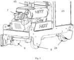
- Fig. 1 to Fig. 15 show an embodiment of a joint milling or cutting device F according to the invention.
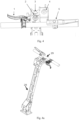
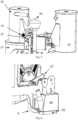
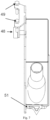
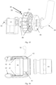
- the partial views according to Fig. 4 to 14 and Fig. 16 and by exploded view according to Fig. 15 the interrelationship of the parts of the device and their position are made clear and the structure of the parts of the device F can also be shown.
- Fig. 1 and Fig. 2 show in perspective view from the right and from the left an embodiment of the joint milling or cutting device F according to the invention.
- the joint milling or cutting device F shown in the drawing has a motor-driven milling disk or cutting blade and a self-propelled drive for dry cutting in surfaces.
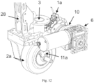
- a two-part, three-track chassis is provided, with the front part having a drive wheel 2a (see Fig. 1 , Fig. 2 , Fig. 3 , Fig. 11 and Fig. 12 ) and the rear part two wheels 8, 9 arranged coaxially at a distance from each other on an axle (see Fig. 1 , Fig. 2 , Fig. 3 , Fig. 6 ).
- a combustion engine 7 is arranged above the axle of the wheels 8, 9 and an electric motor 6 with a gear connected to an accumulator (not shown in the drawing) is also provided.
- a magnetic coupling 10 (see Fig. 12 ).
- a rubber bandage on the drive wheel 2a is characterized by its high load-bearing capacity and durability and enables a high level of grip on the surface.
- the magnetic coupling 10 is a friction clutch, preferably ground in, and then has around 90% of its power. Since the joint milling or cutting device F is operated at a low speed, but the magnetic coupling 10 requires 100% power for the speed for milling/cutting, only a maximum power of 50% is available during operation. This is sufficient, however, since the electric motor 6 with gearbox has an output of 14 Nm and around 22 Nm is available at 50% power of the magnetic coupling. An electric motor 6 with 24 V is preferably provided for the drive. The power is transferred to the wheel shaft via a gear ratio of approx.
- the magnetic clutch 10 preferably a 12V or 24V magnetic clutch 10, is installed according to the invention. With this magnetic clutch 10, the drive can be switched on and off without any problem.
- control electronics connected to the magnetic clutch 10 are provided for slowly starting and braking the drive wheel 2a.
- an approximately vertically extending guide rod 28 is provided, which carries at the free end a horizontally extending handlebar 29 with two handles and an actuating lever 1 for a hydraulic disc brake 1a and a dead man's switch 5 attached to it (see Fig. 4 and Fig. 4a ).
- the front part is connected to the rear part of the chassis via a horizontally pivoting swivel joint 3 (see Fig. 11 and Fig. 12 ).
- the joint milling or cutting device F has a cyclone separation device which comprises a coarse dust vortex cyclone 22 with an associated dust container 21 and a fine dust cyclone 25 with an internal fine filter (see Fig. 2 ).
- a coarse dust pre-filter 26 is arranged in the air intake tract of the combustion engine 7 to its air filter (see Fig. 5 ).
- a level sensor 24 is arranged on the dust container 21 (see Fig. 13 ).
- the joint milling or cutting device F has a battery (not shown in the drawing) and the combustion engine 7 charges it by means of a charging coil (not shown in the drawing).
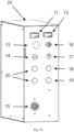
- the handlebar 29 carries an operating device on which a potentiometer 2 is arranged for setting the milling speed (see Fig. 4 ) and furthermore an operating and display device 23 arranged on the rear part of the chassis (see Fig. 10 ) with a display for speed indication.
- the operating and display device 23 has an operating hour counter 12, an EMERGENCY/OFF button 13, a USB charging socket 14, LED flashing lights 15, a charging control light 18, an engine oil control light 19, an on/off switch 17 for the flashing lights 15 and a hand throttle potentiometer 16 for the speed of the combustion engine 7.
- a manually operated depth adjustment 27 for a milling disk, preferably designed as a diamond disk, is arranged on the rear part of the chassis.
- the combustion engine 7 drives a vacuum fan 30 (see Fig. 15 ).
- the vacuum fan 30 has a bearing block 31, a fan shaft 32, a blade fan 33, an intake nozzle 34 (flexible and made of PVC), a cone 35 (made of aluminum) and two spacers 36.
- the cone 35 is positioned at the entrance of the housing in such a way that, in conjunction with the blade fan 33, it creates an effective air vortex and thus increases the air volume or the resulting vacuum.
- the two spacers 36 clamp the blade fan 33 and thus set it in rotational motion via the fan shaft 32.
- Fig. 6 to 9 show a design for a protective hood 46 in detail.
- the protective hood 46 has a polyurethane roller 48, screws 49 (preferably M8 screws) for the depth limitation, a horsehair brush 50 and a visor 51 for optical alignment on the joint.
- Fig. 16 shows a top view of a design for a hose connection as a locking system in the cyclone separator according to Fig. 5
- This hose connection preferably made of aluminum, is a maintenance-free solution and is easy to open and close again.
- the hose connection has a coupling (female) 40, a plug 44 (male), a lever 41 and a holder 42 for an operating aid 43, whereby the operating aid 43 is secured in the holder 42 (hole) by means of a lever lock 52 (spring pin).
- the joint milling or cutting device F according to the invention is described in more detail below.
- the device F has in particular a petrol injection engine 7 with 23 hp, whereby, in order to guarantee a longer service life of the combustion engine 7, the coarse dust pre-filter 26 is installed in the air intake tract of the combustion engine 7 in addition to the existing air filter. This ensures that the coarse Dust particles are captured in the coarse dust pre-filter 26, thus relieving the load on the air filter (fine filter) of the combustion engine 7.
- This combustion engine 7 is mainly used to accelerate the cutting shaft at a ratio of 1:1.7 to around 6000 rpm. This speed is required to achieve a good cutting result with the hard metal milling disc, preferably a milling disc designed as a diamond disc (not shown in the drawing).
- a milling disc designed as a diamond disc a special solder improves the heat transfer from a cutting diamond to the tool body, which results in a longer service life for the discs.
- a St52-3 is used as the carrier material for the diamond milling discs.
- Diamond segments are attached to the front side. These segments are welded onto the asphalt with a TIG copper/tin welding rod because of their excellent heat transfer.
- the combustion engine 7 also drives the vacuum fan 30 via a V-belt.
- This fan 30 is required to generate the vacuum for suction in both cyclones and causes the cutting dust to be sucked off the diamond disk.
- a side channel compressor (with blow-out opening) can be used instead of a vacuum fan 30. This increases the vacuum of conventional systems from 0.15 bar to up to 0.4 bar, which results in a significantly higher suction power in conjunction with the protective hood 46.
- the dust is sucked into the coarse dust cyclone 22 from the protective hood 46, which is mounted above the diamond disk and which reaches close to the (road) surface by means of the horsehair brush 50.
- the horsehair brush 50 (for a tight seal between asphalt and protection) can be easily changed by the operator using a locking system.
- the protective hood 46 can be automatically lowered above the milling disk designed as a diamond disk by means of the control electronics, preferably a program-controlled processor, of the joint milling or cutting device F according to the invention.
- the operator only has to set the desired height of the Adjust the protective cover 46, then the desired setting is made automatically each time.
- the milling dust is sucked into the coarse dust vortex cyclone 22 at high speed, where it hits a 5 mm thick V2A plate that prevents the cyclone from grinding through too quickly.
- the dust is then transported downwards in the vortex current into the dust container/coarse dust bucket 21, with the coarse dust particles remaining in the dust container 21, while the finer particles are drawn into the fine dust cyclone 25 by the prevailing negative pressure, where they also hit a 2 mm thick V2A wear plate.
- the finer particles get caught on the fine filter and some of them fall to the base of the fine filter.
- the dust container/coarse dust bucket 21 must be emptied after around 80 m of joint, and the filter in the fine dust cyclone 25 should be knocked out every 160 m to 240 m. Care must be taken to knock it out gently so that the filter fleece is not damaged.
- the fan hose/hose connection is connected to the fine filter cover of the fine dust cyclone 25. All hose connections are designed with the locking system described above.
- the combustion engine 7 has a third task, namely it supplies the battery/accumulator with sufficient power.
- the 16A charging coil ensures sufficient power supply.
- the battery/accumulator in particular 12V/35Ah, has the task of starting the combustion engine 7.
- the most important task of the accumulator/battery is to provide sufficient electrical energy for the drive.
- the drive is therefore dependent on the electrical energy available from the accumulator/battery.
- the ignition on the combustion engine 7 must be switched on.
- switch 4 on the control lever must be switched on and potentiometer 2 must be in the "0" position. If the operator now presses the dead man's switch 5 with with one hand is also a safety device for the operator, then he can easily turn the potentiometer 2 with the other hand until the machine has reached the desired speed. The optimum cutting speed is reached when the machine generates an acceleration of approx.
- the drive is preferably powered by a brushed DC gear motor 6 with 24V, with outputs of 14 Nm or 27 Nm available. 100% of the traction is available and there are no slippage problems. Both motors therefore have enough power to effortlessly manage a gradient of more than 10%.
- the magnetic clutch 10 is used to be able to push the machine easily even when "idling", to generate a slip-free traction to the drive wheel 2a and to have a parking brake. This magnetic clutch 10 has enough power to act as a parking brake when the combustion engine 7 has been switched off. The magnetic clutch 10 also acts as a blocking brake when the operator releases the dead man switch 5, for whatever reason. The circuit is connected in such a way that this dead man switch 5 automatically interrupts the flow of current to the brushed DC gear motor 6.
- the odometer 11a is mounted inside the drive wheel 2a with rubber bandage. This location was deliberately chosen to be hidden in order to avoid mechanical damage from the outside.
- the hydraulic disc brake 1a was installed.
- This disc brake 1a is also able to hold the device F securely on inclines and thus also has the function of a mechanical parking brake.
- a locking lever is set using the actuating lever 1 and thus the device F is just as secure as with the electric parking brake/magnetic clutch 10, but has the advantage that no power is required. This is an advantage if the joint milling or cutting device F is left unattended for a long time and the accumulator/battery could break down, thus de-energizing the magnetic clutch 10 and causing the device F to roll uncontrollably.
- LED flashing lights 15 are installed on four sides for maximum safety in the work area and are approved according to ECE standards. These LED flashing lights 15 can be switched on and off as required.
- the switch 17 for this is installed on the operating and display device 23, as is the EMERGENCY/STOP button 13.
- the USB charging socket 14 is installed in order to ensure that the operator of the joint milling or cutting device F according to the invention can be reached at all times, but also for the operator to communicate.
- the operator can easily charge his cell phone here, so that he always has sufficient battery power; a safety feature even in the event of an emergency.
- the power supply to the components of the joint milling or cutting device F according to the invention is via flexible electrical cables connected to the accumulator/battery.
- the joint milling or cutting device F enables a efficient and fast road repair with a significantly longer service life for the tool.
- no dust pollution/environmental pollution from fine dust is to be expected with dry cutting and road surfaces with gradients of more than 10% can be milled without support and without slippage.
Landscapes
- Engineering & Computer Science (AREA)
- Mining & Mineral Resources (AREA)
- Mechanical Engineering (AREA)
- Architecture (AREA)
- Civil Engineering (AREA)
- Structural Engineering (AREA)
- Road Repair (AREA)
Applications Claiming Priority (1)
| Application Number | Priority Date | Filing Date | Title |
|---|---|---|---|
| DE102023003333.2A DE102023003333B3 (de) | 2023-08-13 | 2023-08-13 | Fugenfräß- oder Schneidgerät mit einem Fahrantrieb mit Magnetkupplung und Verfahren zu dessen Steuerung |
Publications (2)
| Publication Number | Publication Date |
|---|---|
| EP4509657A1 true EP4509657A1 (fr) | 2025-02-19 |
| EP4509657B1 EP4509657B1 (fr) | 2025-12-10 |
Family
ID=92408873
Family Applications (1)
| Application Number | Title | Priority Date | Filing Date |
|---|---|---|---|
| EP24020266.3A Active EP4509657B1 (fr) | 2023-08-13 | 2024-08-13 | Appareil de fraisage ou de coupe de joints doté d'une traction à embrayage magnétique et son procédé de commande |
Country Status (3)
| Country | Link |
|---|---|
| EP (1) | EP4509657B1 (fr) |
| DE (1) | DE102023003333B3 (fr) |
| PL (1) | PL4509657T3 (fr) |
Citations (16)
| Publication number | Priority date | Publication date | Assignee | Title |
|---|---|---|---|---|
| DE3815640A1 (de) | 1988-05-07 | 1989-11-16 | Lissmac Maschinenbau Gmbh | Verfahrbarer fugenschneider |
| DE9000710U1 (de) | 1990-01-23 | 1990-03-29 | Baumgärtner, Hans | Vorrichtung zum Transportieren von Medien mittels thermisch isolierten Rohren |
| DE9104602U1 (de) | 1991-04-16 | 1991-06-13 | Lissmac Maschinenbau und Diamantwerkzeuge GmbH, 7954 Bad Wurzach | Verfahrbarer Fugenschneider |
| DE9103718U1 (de) | 1991-03-26 | 1991-06-27 | Rupprecht, Richard, 8560 Lauf | Fugenfräs- oder -schneidgerät |
| DE4408396A1 (de) | 1994-03-12 | 1995-09-21 | Mafu Gmbh | Fugenfräse |
| DE29511771U1 (de) | 1995-07-21 | 1995-12-07 | Rupprecht, Richard, 91207 Lauf | Fugenfräs-Fugenpflug oder Bürstgerät |
| DE29820188U1 (de) | 1998-11-11 | 1999-01-07 | Lissmac Maschinenbau und Diamantwerkzeuge GmbH, 88410 Bad Wurzach | Fahrbarer Fugenschneider |
| US6102022A (en) * | 1997-01-07 | 2000-08-15 | Crafco, Incorporated | Pavement cutting machine |
| DE29908397U1 (de) | 1999-05-15 | 2000-09-21 | Rupprecht, Richard, 91207 Lauf | Asphaltfräse |
| DE20312712U1 (de) | 2003-08-18 | 2003-11-06 | Kresnik, Herbert, St. Stefan / Lavanttal | Absaugvorrichtung für Rissefräse |
| DE10348481B3 (de) | 2003-10-14 | 2005-03-10 | Richard Rupprecht | Fugenfräse auf Tretrollerbasis |
| DE102004050183B3 (de) | 2003-10-14 | 2006-06-01 | Richard Rupprecht | Kombiniertes Fugenfräs- und Schleifgerät auf Tretrollerbasis |
| DE102013001715A1 (de) * | 2013-02-01 | 2014-08-07 | Lissmac Maschinenbau Gmbh | "Bodentrennschleifvorrichtung insbesondere mit einem motorischen Fahrantrieb" |
| DE202016007446U1 (de) * | 2016-12-07 | 2016-12-19 | Erhard Beck | Führungswagen für einen Fugenschneider |
| DE102016001290A1 (de) | 2016-02-05 | 2017-08-10 | Andreas Rupprecht | Fahrbares Gerät zum Trocken- und Nassschnitt in Oberflächen mit Schnittwinkeleinstellung, Feinstaubabsaugung, Liftachse und Schwenkarm für Bedienpult |
| EP3456197A1 (fr) | 2017-09-13 | 2019-03-20 | Alfred Kärcher SE & Co. KG | Fraises pour joints de carrelage à désherber |
Family Cites Families (1)
| Publication number | Priority date | Publication date | Assignee | Title |
|---|---|---|---|---|
| DE900071C (de) * | 1942-10-18 | 1953-12-17 | Hermann Kluftinger Dipl Ing | Fasergutzufuehreinrichtung an Krempeln, Schlagmaschinen u. dgl. |
-
2023
- 2023-08-13 DE DE102023003333.2A patent/DE102023003333B3/de active Active
-
2024
- 2024-08-13 PL PL24020266.3T patent/PL4509657T3/pl unknown
- 2024-08-13 EP EP24020266.3A patent/EP4509657B1/fr active Active
Patent Citations (16)
| Publication number | Priority date | Publication date | Assignee | Title |
|---|---|---|---|---|
| DE3815640A1 (de) | 1988-05-07 | 1989-11-16 | Lissmac Maschinenbau Gmbh | Verfahrbarer fugenschneider |
| DE9000710U1 (de) | 1990-01-23 | 1990-03-29 | Baumgärtner, Hans | Vorrichtung zum Transportieren von Medien mittels thermisch isolierten Rohren |
| DE9103718U1 (de) | 1991-03-26 | 1991-06-27 | Rupprecht, Richard, 8560 Lauf | Fugenfräs- oder -schneidgerät |
| DE9104602U1 (de) | 1991-04-16 | 1991-06-13 | Lissmac Maschinenbau und Diamantwerkzeuge GmbH, 7954 Bad Wurzach | Verfahrbarer Fugenschneider |
| DE4408396A1 (de) | 1994-03-12 | 1995-09-21 | Mafu Gmbh | Fugenfräse |
| DE29511771U1 (de) | 1995-07-21 | 1995-12-07 | Rupprecht, Richard, 91207 Lauf | Fugenfräs-Fugenpflug oder Bürstgerät |
| US6102022A (en) * | 1997-01-07 | 2000-08-15 | Crafco, Incorporated | Pavement cutting machine |
| DE29820188U1 (de) | 1998-11-11 | 1999-01-07 | Lissmac Maschinenbau und Diamantwerkzeuge GmbH, 88410 Bad Wurzach | Fahrbarer Fugenschneider |
| DE29908397U1 (de) | 1999-05-15 | 2000-09-21 | Rupprecht, Richard, 91207 Lauf | Asphaltfräse |
| DE20312712U1 (de) | 2003-08-18 | 2003-11-06 | Kresnik, Herbert, St. Stefan / Lavanttal | Absaugvorrichtung für Rissefräse |
| DE10348481B3 (de) | 2003-10-14 | 2005-03-10 | Richard Rupprecht | Fugenfräse auf Tretrollerbasis |
| DE102004050183B3 (de) | 2003-10-14 | 2006-06-01 | Richard Rupprecht | Kombiniertes Fugenfräs- und Schleifgerät auf Tretrollerbasis |
| DE102013001715A1 (de) * | 2013-02-01 | 2014-08-07 | Lissmac Maschinenbau Gmbh | "Bodentrennschleifvorrichtung insbesondere mit einem motorischen Fahrantrieb" |
| DE102016001290A1 (de) | 2016-02-05 | 2017-08-10 | Andreas Rupprecht | Fahrbares Gerät zum Trocken- und Nassschnitt in Oberflächen mit Schnittwinkeleinstellung, Feinstaubabsaugung, Liftachse und Schwenkarm für Bedienpult |
| DE202016007446U1 (de) * | 2016-12-07 | 2016-12-19 | Erhard Beck | Führungswagen für einen Fugenschneider |
| EP3456197A1 (fr) | 2017-09-13 | 2019-03-20 | Alfred Kärcher SE & Co. KG | Fraises pour joints de carrelage à désherber |
Also Published As
| Publication number | Publication date |
|---|---|
| DE102023003333B3 (de) | 2024-11-07 |
| EP4509657B1 (fr) | 2025-12-10 |
| PL4509657T3 (pl) | 2026-04-20 |
Similar Documents
| Publication | Publication Date | Title |
|---|---|---|
| DE102016001290A1 (de) | Fahrbares Gerät zum Trocken- und Nassschnitt in Oberflächen mit Schnittwinkeleinstellung, Feinstaubabsaugung, Liftachse und Schwenkarm für Bedienpult | |
| DE202022001468U1 (de) | Offene Schutzhaube mit integrierter Absaugung für ein fahrbares Gerät zum Trockenschnitt in Oberflächen | |
| US4204714A (en) | Pavement cutting machine with pad to stabilize and brake machine | |
| DE69307864T2 (de) | Umwandelbare Kehrvorrichtung | |
| US6733086B1 (en) | Vacuum system for milling machine | |
| DE112010000866T5 (de) | Motorisiertes Schneidgerät, motorisiertes Schneidgerät mit Rädern und Schneidverfahren | |
| US4175788A (en) | Pavement cutting machine | |
| DE102004050183B3 (de) | Kombiniertes Fugenfräs- und Schleifgerät auf Tretrollerbasis | |
| DE102007028848A1 (de) | Fahr-/Verschiebbares Gerät mit Heizeinrichtung, Rüttelplatte, Fräsrad, Fugeneindrückrad oder Klopfteil | |
| DE2727353A1 (de) | Fahrzeug mit vierradantrieb und gelenkrahmenlenkung | |
| CH674658A5 (fr) | ||
| DE3686977T2 (de) | Geraet zum verlegen von bordsteinen, verbundpflastersteinen und aehnliches. | |
| DE102023003333B3 (de) | Fugenfräß- oder Schneidgerät mit einem Fahrantrieb mit Magnetkupplung und Verfahren zu dessen Steuerung | |
| DE102008006318B3 (de) | Fugenreinigungsmaschine für gepflasterte Flächen | |
| US6176551B1 (en) | Surface preparation apparatus and method of using the same | |
| DE102005049766B4 (de) | Handgeführter Trennschleifer | |
| DE102006026529B4 (de) | Fahrbares Gerät mit Asphaltflächenheizer, Walze, Igel-Fräse, Fugeneindrückrad zur Fugenherstellung oder-Reparatur | |
| DE3617681A1 (de) | Selbstfahrbare arbeitsmaschine mit wechselwerkzeugen oder -geraeten | |
| DE19819990C2 (de) | Schienenschleifvorrichtung | |
| DE3420989A1 (de) | Anbaugeraet fuer den anbau an hydraulikbagger, baggerlader, frontlader und andere traegergeraete | |
| EP0386307B1 (fr) | Chasse-neige | |
| DE202010000161U1 (de) | Vorrichtung zum Einbringen von Fugen | |
| EP1788156A2 (fr) | Outil pour l'entretien du paysage guidé manuellement | |
| DE2407514A1 (de) | Tellerbesen-anordnung an kehrmaschinen | |
| DE102005033199A1 (de) | Fahrbare Vorrichtung zur Asphalt- und Fugenreparatur und Entfernung von Verunreinigungen von Oberflächen |
Legal Events
| Date | Code | Title | Description |
|---|---|---|---|
| PUAI | Public reference made under article 153(3) epc to a published international application that has entered the european phase |
Free format text: ORIGINAL CODE: 0009012 |
|
| STAA | Information on the status of an ep patent application or granted ep patent |
Free format text: STATUS: THE APPLICATION HAS BEEN PUBLISHED |
|
| AK | Designated contracting states |
Kind code of ref document: A1 Designated state(s): AL AT BE BG CH CY CZ DE DK EE ES FI FR GB GR HR HU IE IS IT LI LT LU LV MC ME MK MT NL NO PL PT RO RS SE SI SK SM TR |
|
| STAA | Information on the status of an ep patent application or granted ep patent |
Free format text: STATUS: REQUEST FOR EXAMINATION WAS MADE |
|
| 17P | Request for examination filed |
Effective date: 20250325 |
|
| GRAP | Despatch of communication of intention to grant a patent |
Free format text: ORIGINAL CODE: EPIDOSNIGR1 |
|
| STAA | Information on the status of an ep patent application or granted ep patent |
Free format text: STATUS: GRANT OF PATENT IS INTENDED |
|
| GRAS | Grant fee paid |
Free format text: ORIGINAL CODE: EPIDOSNIGR3 |
|
| RIC1 | Information provided on ipc code assigned before grant |
Ipc: E01C 23/09 20060101AFI20250811BHEP Ipc: B28D 1/04 20060101ALI20250811BHEP Ipc: B28D 1/18 20060101ALI20250811BHEP Ipc: B28D 7/02 20060101ALN20250811BHEP |
|
| INTG | Intention to grant announced |
Effective date: 20250903 |
|
| GRAA | (expected) grant |
Free format text: ORIGINAL CODE: 0009210 |
|
| STAA | Information on the status of an ep patent application or granted ep patent |
Free format text: STATUS: THE PATENT HAS BEEN GRANTED |
|
| AK | Designated contracting states |
Kind code of ref document: B1 Designated state(s): AL AT BE BG CH CY CZ DE DK EE ES FI FR GB GR HR HU IE IS IT LI LT LU LV MC ME MK MT NL NO PL PT RO RS SE SI SK SM TR |
|
| REG | Reference to a national code |
Ref country code: CH Ref legal event code: F10 Free format text: ST27 STATUS EVENT CODE: U-0-0-F10-F00 (AS PROVIDED BY THE NATIONAL OFFICE) Effective date: 20251210 Ref country code: GB Ref legal event code: FG4D Free format text: NOT ENGLISH |
|
| REG | Reference to a national code |
Ref country code: DE Ref legal event code: R096 Ref document number: 502024000461 Country of ref document: DE |
|
| REG | Reference to a national code |
Ref country code: IE Ref legal event code: FG4D Free format text: LANGUAGE OF EP DOCUMENT: GERMAN |
|
| REG | Reference to a national code |
Ref country code: NL Ref legal event code: FP |
|
| PG25 | Lapsed in a contracting state [announced via postgrant information from national office to epo] |
Ref country code: ES Free format text: LAPSE BECAUSE OF FAILURE TO SUBMIT A TRANSLATION OF THE DESCRIPTION OR TO PAY THE FEE WITHIN THE PRESCRIBED TIME-LIMIT Effective date: 20251210 |
|
| REG | Reference to a national code |
Ref country code: LT Ref legal event code: MG9D |
|
| PG25 | Lapsed in a contracting state [announced via postgrant information from national office to epo] |
Ref country code: NO Free format text: LAPSE BECAUSE OF FAILURE TO SUBMIT A TRANSLATION OF THE DESCRIPTION OR TO PAY THE FEE WITHIN THE PRESCRIBED TIME-LIMIT Effective date: 20260310 |
|
| PG25 | Lapsed in a contracting state [announced via postgrant information from national office to epo] |
Ref country code: FI Free format text: LAPSE BECAUSE OF FAILURE TO SUBMIT A TRANSLATION OF THE DESCRIPTION OR TO PAY THE FEE WITHIN THE PRESCRIBED TIME-LIMIT Effective date: 20251210 Ref country code: HR Free format text: LAPSE BECAUSE OF FAILURE TO SUBMIT A TRANSLATION OF THE DESCRIPTION OR TO PAY THE FEE WITHIN THE PRESCRIBED TIME-LIMIT Effective date: 20251210 |
|
| PGFP | Annual fee paid to national office [announced via postgrant information from national office to epo] |
Ref country code: RO Payment date: 20260309 Year of fee payment: 3 |
|
| PG25 | Lapsed in a contracting state [announced via postgrant information from national office to epo] |
Ref country code: RS Free format text: LAPSE BECAUSE OF FAILURE TO SUBMIT A TRANSLATION OF THE DESCRIPTION OR TO PAY THE FEE WITHIN THE PRESCRIBED TIME-LIMIT Effective date: 20260310 |
|
| PGFP | Annual fee paid to national office [announced via postgrant information from national office to epo] |
Ref country code: TR Payment date: 20260310 Year of fee payment: 3 |
|
| PGFP | Annual fee paid to national office [announced via postgrant information from national office to epo] |
Ref country code: CZ Payment date: 20260302 Year of fee payment: 3 |
|
| PGFP | Annual fee paid to national office [announced via postgrant information from national office to epo] |
Ref country code: PL Payment date: 20260305 Year of fee payment: 3 |
|
| PG25 | Lapsed in a contracting state [announced via postgrant information from national office to epo] |
Ref country code: LV Free format text: LAPSE BECAUSE OF FAILURE TO SUBMIT A TRANSLATION OF THE DESCRIPTION OR TO PAY THE FEE WITHIN THE PRESCRIBED TIME-LIMIT Effective date: 20251210 |