EP4509689A1 - Solares stromversorgungssystem für einen elektromotor einer motorbetriebenen jalousie - Google Patents
Solares stromversorgungssystem für einen elektromotor einer motorbetriebenen jalousie Download PDFInfo
- Publication number
- EP4509689A1 EP4509689A1 EP24186103.8A EP24186103A EP4509689A1 EP 4509689 A1 EP4509689 A1 EP 4509689A1 EP 24186103 A EP24186103 A EP 24186103A EP 4509689 A1 EP4509689 A1 EP 4509689A1
- Authority
- EP
- European Patent Office
- Prior art keywords
- blind
- motor
- casing
- solar
- profile
- Prior art date
- Legal status (The legal status is an assumption and is not a legal conclusion. Google has not performed a legal analysis and makes no representation as to the accuracy of the status listed.)
- Withdrawn
Links
Images



Classifications
-
- E—FIXED CONSTRUCTIONS
- E06—DOORS, WINDOWS, SHUTTERS, OR ROLLER BLINDS IN GENERAL; LADDERS
- E06B—FIXED OR MOVABLE CLOSURES FOR OPENINGS IN BUILDINGS, VEHICLES, FENCES OR LIKE ENCLOSURES IN GENERAL, e.g. DOORS, WINDOWS, BLINDS, GATES
- E06B9/00—Screening or protective devices for wall or similar openings, with or without operating or securing mechanisms; Closures of similar construction
- E06B9/02—Shutters, movable grilles, or other safety closing devices, e.g. against burglary
- E06B9/08—Roll-type closures
- E06B9/11—Roller shutters
- E06B9/17—Parts or details of roller shutters, e.g. suspension devices, shutter boxes, wicket doors, ventilation openings
-
- E—FIXED CONSTRUCTIONS
- E06—DOORS, WINDOWS, SHUTTERS, OR ROLLER BLINDS IN GENERAL; LADDERS
- E06B—FIXED OR MOVABLE CLOSURES FOR OPENINGS IN BUILDINGS, VEHICLES, FENCES OR LIKE ENCLOSURES IN GENERAL, e.g. DOORS, WINDOWS, BLINDS, GATES
- E06B1/00—Border constructions of openings in walls, floors, or ceilings; Frames to be rigidly mounted in such openings
- E06B1/04—Frames for doors, windows, or the like to be fixed in openings
- E06B1/34—Coverings, e.g. protecting against weather, for decorative purposes
- E06B1/342—Reveal covering members disposed alongside of a window frame
-
- E—FIXED CONSTRUCTIONS
- E06—DOORS, WINDOWS, SHUTTERS, OR ROLLER BLINDS IN GENERAL; LADDERS
- E06B—FIXED OR MOVABLE CLOSURES FOR OPENINGS IN BUILDINGS, VEHICLES, FENCES OR LIKE ENCLOSURES IN GENERAL, e.g. DOORS, WINDOWS, BLINDS, GATES
- E06B9/00—Screening or protective devices for wall or similar openings, with or without operating or securing mechanisms; Closures of similar construction
- E06B9/24—Screens or other constructions affording protection against light, especially against sunshine; Similar screens for privacy or appearance; Slat blinds
- E06B2009/2476—Solar cells
Definitions
- the invention a solar power supply system for the electric motor of a motorised blind, relates to a modular assembly for blinds, of both doors and windows, of those that have a motorised drive via an electric motor.
- the system comprises at least one solar panel that, as a means of autonomous power supply using solar energy, is integrated into a lower casing, preferably arranged perpendicular in the lower portion of the door or window where the blind is installed as a shelf.
- the system makes it possible to adapt blinds that roll manually using a belt or blinds that have an electric motor connected to an electrical grid installation to a solar power supply system. This thus avoids the need to provide installations to carry the power supply wiring of the motor from a power outlet of the electrical grid.
- the system comprises all the elements for the installation of a new blind, but without ruling out its installation on doors or windows with existing blinds, in which case the system comprises at least the lower casing with the solar power supply means.
- the field of application of the present invention falls within the sector of the industry dedicated to the manufacture of blinds, focusing particularly on the field of blinds with automatic drive via an electric motor.
- Blinds are known that have, instead of a manually driven belt or crank, an automatic drive mechanism that allows the blind to be raised and lowered due to the work of a small electric motor normally incorporated in the upper drawer of the door or window where the shaft or drum on which the blind is rolled is located.
- Blinds of this type although much more practical than manually driven blinds since an effort does not need to be made, have the drawback that they require the existence of an electrical installation that carries the wiring that must power the motor from the electrical panel of the home or premises, which, in addition to being financially costly, can sometimes be complicated, depending on each case.
- the objective of the present invention is to solve this problem by developing a new type of motorised blind that has completely autonomous installation and operation and does not have the need to depend on any electrical wiring installation to connect it to an electrical panel or power outlet.
- the object of the present invention is a solar power supply system for an electric motor of a motorised blind according to claim 1.
- the system of the invention comprises a casing with a grooved lower profile that can be coupled to an upper closing cover used to protect at least one solar panel located between said profile and said cover, said solar panel having a connector also located inside the casing to connect the solar panel to the motor.
- the system is a modular assembly for blinds, of both doors and windows, for the motorised drive thereof via an electric motor.
- it comprises at least one or more solar panels, as a means of autonomous power supply using solar energy, integrated into a casing that, as a shelf, is coupled to the lower portion of the door or window on which the blind is installed.
- the blind is preferably integrated into a frame with respective hollow lateral vertical profiles through which the wiring of said panels is passed so that it remains hidden, and which, in turn, are coupled to the motor inside the upper drawer that houses said motor, the roller shaft of the blind, as well as any mechanism for rolling and unrolling the blind.
- the system may also comprise the motor and even the blind itself, so that it has all the elements for the installation of a new blind, but without ruling out its application to install it on doors or windows with existing blinds that are to be motorised.
- the system comprises at least the casing that houses the at least one solar panel, arranged as a lower shelf with the solar power supply means and, preferably, also the electric motor with the electrical charging battery.
- the object of the invention is a solar power system for a door or window blind that comprises one or more solar panels that are installed on the lower portion of the door or window, housed in a specific flat and hollow casing in the form of a shelf where they are protected inside a lower grooved profile with an upper closing cover and through which the wires that extend to the blind motor located in the upper drawer run.
- the wires are preferably inserted into at least one of the two vertical profiles used to guide the blind and that are internally hollow for this purpose, forming part of a frame. Said frame, with the vertical profiles and the casing, is coupled under the upper drawer where the motor and the rolling mechanism of the blind are housed.
- the motor in a preferred embodiment, also has an external electrical connection in case there is a problem with solar charging.
- the motor comprises a control board, which allows the motor to be activated via a remote control, although the use of push button panels is not ruled out, in which case, preferably, they are included integrated into the aforementioned profiles of the frame.
- the system mainly comprises the following elements:
- system may comprise:
- the solar panel or panels are therefore arranged on the lower casing, so that light will shine directly on them to capture solar energy and such that when the blind is in the closed position, it is located on the casing, preferably in middle or in front of the panel or panels, preventing (or making it difficult) for someone to steal or damage them.
- the system comprises at least the lower shelf-type casing with the solar panels.
- the system will comprise all the aforementioned elements, with the exception of the blind itself, adapting the upper drawer with the electric motor, the new frame with the profiles and the lower shelf casing with the solar panels to the dimensions of the window and to the type of existing blind.
- said lower casing is made up of a lower profile having a length corresponding to the width of the door or window and having a grooved configuration, such that it defines a space to incorporate the solar panel or panels, and a upper closing cover that is coupled to said lower profile protecting the solar panels, and that preferably comprises one or more perforated sections, which are located in correspondence with the position of the panels, normally located in the centre of the lower profile, to allow light to pass therethrough.
- it may comprise one or two lateral blind cover sections that cover the rest of the lower profile, hiding the wiring that runs through the same.
- said lower profile of the shelf has specific lateral caps provided for this purpose.
- the electric motor of the blind at the time of installation has a pre-charged battery and has a connection to charge the battery externally and a connection to connect the solar panel.
- the main advantage of the system object of the invention is that installations to carry wires from the electrical panel of the home or premises are avoided.
- the lower system with the panel or panels can even be installed on windows and doors with existing blinds that are to be converted into electric blinds.
- the invention allows the solar panel or panels to be integrated as a construction element of the window or door. Likewise, it can be integrated not only into windows but also into doors, for example, sliding doors, for which the shelf-type casing of the grooved profile with the panels is incorporated into the floor, preferably embedded in a recess made for this purpose, so that it remains flush with said floor.
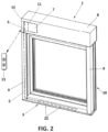
- the system (1) of the invention comprises at least one or more solar panels (2) housed in a casing (3) suitable for installation thereof in the lower portion and perpendicular to the door or window with the blind (4) for which it is intended as a shelf, and through the inside of said casing (3) the wires (5) run hidden with the corresponding connector (6) to an electric motor (7) that provides the rolling movement to raise and lower the blind (4) located in an upper drawer (8).
- said casing (3) that can be installed as a lower shelf comprises at least a grooved lower profile (30), in which the solar panel or panels (2) inserted snugly and an upper closing cover (31) used to protect said panels (2) fit.
- the lower profile (30) has a length corresponding to the width of the door or window on which it is installed and a grooved configuration determined by the existence of at least one longitudinal partition (301), such that it defines at least one elongated space (302) suitable for snugly incorporating one or more aligned solar panels (2) so that once the casing (3) is installed as a shelf and with the blind (4) in the lowered position, said blind (4) is located with its lower edge resting on said panel or panels (2).
- said lower profile (30) has one or more water drainage holes (303) distributed along the same.
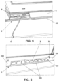
- the lower profile (30) is closed at its ends by means of caps (32) of a complementary configuration to fit snugly at said ends, as shown in figures 7 and 8 .
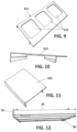
- the upper closing cover (31) that is coupled to said lower profile (30) protecting the solar panels (2) comprises one or more perforated sections (311), which are located in correspondence with the position of the panels (2), normally located in the centre of the lower profile (30), such that they define windows (312) that allow light to pass therethrough so that the panels (2) can capture solar radiation, and one or two blind cover sections (313), in other words, without said windows, which cover the rest of the lower profile (30) hiding the connection wires (5).
- the system (1) further comprises respective lateral vertical profiles (9) that define the lateral guides (90) for the blind (4) and that, together with the lower casing (3), form a frame (10) that can be coupled under the upper drawer (8) where the motor (7) and the rolling mechanism of the blind (4) are housed, which lateral profiles (9) are internally hollow and through the inside of which, in at least one of them, the connection wires (5) of the panels (2) run hidden, as shown schematically in figure 2 , in figure 3-A and in the enlarged detail of figure 3-B .
- the electric motor (7) in addition to a recharging battery (11) with the connection to the connector (6) of the wires (5) of the solar panel or panels (2), the electric motor (7) also has an external electrical connection (12) for recharging said battery (11).
- the motor (7) is activated via a remote control (13) and, optionally, also by a push button panel (not shown), in which case, preferably, it is included integrated into one of the lateral profiles (9) of the frame (10), on the inside of the door or window.
- the system (1) comprises all the previously described elements, including the blind (4) itself, as a complete assembly, in other words:
Landscapes
- Engineering & Computer Science (AREA)
- Structural Engineering (AREA)
- Civil Engineering (AREA)
- Architecture (AREA)
- Blinds (AREA)
Applications Claiming Priority (1)
| Application Number | Priority Date | Filing Date | Title |
|---|---|---|---|
| ES202331352U ES1305415Y (es) | 2023-07-21 | 2023-07-21 | Sistema de alimentacion solar de un motor electrico de una persiana motorizada |
Publications (1)
| Publication Number | Publication Date |
|---|---|
| EP4509689A1 true EP4509689A1 (de) | 2025-02-19 |
Family
ID=89661817
Family Applications (1)
| Application Number | Title | Priority Date | Filing Date |
|---|---|---|---|
| EP24186103.8A Withdrawn EP4509689A1 (de) | 2023-07-21 | 2024-07-02 | Solares stromversorgungssystem für einen elektromotor einer motorbetriebenen jalousie |
Country Status (2)
| Country | Link |
|---|---|
| EP (1) | EP4509689A1 (de) |
| ES (1) | ES1305415Y (de) |
Citations (5)
| Publication number | Priority date | Publication date | Assignee | Title |
|---|---|---|---|---|
| DE8504238U1 (de) * | 1985-02-15 | 1985-06-13 | AluTeam Bautechnik GmbH, 5440 Mayen | Befestigungsvorrichtung für eine Fensterbank |
| DE20319217U1 (de) * | 2003-06-02 | 2004-05-19 | Hiro Solarbauelemente Gmbh | Solarfensterbank |
| GB2419935A (en) * | 2004-11-09 | 2006-05-10 | Susan Robinson | Window lighting unit |
| EP3175072B1 (de) * | 2014-07-31 | 2018-12-19 | Friedrich Karl Rinn | Vorrichtung zum betätigen von antrieben für bewegliche schutzanlagen und verfahren zur verwendung einer vorrichtung zum betätigen von antrieben für bewegliche schutzanlagen |
| DE202021103295U1 (de) * | 2021-06-18 | 2022-09-22 | ST Extruded Products Germany GmbH | Abdecksystem |
-
2023
- 2023-07-21 ES ES202331352U patent/ES1305415Y/es active Active
-
2024
- 2024-07-02 EP EP24186103.8A patent/EP4509689A1/de not_active Withdrawn
Patent Citations (5)
| Publication number | Priority date | Publication date | Assignee | Title |
|---|---|---|---|---|
| DE8504238U1 (de) * | 1985-02-15 | 1985-06-13 | AluTeam Bautechnik GmbH, 5440 Mayen | Befestigungsvorrichtung für eine Fensterbank |
| DE20319217U1 (de) * | 2003-06-02 | 2004-05-19 | Hiro Solarbauelemente Gmbh | Solarfensterbank |
| GB2419935A (en) * | 2004-11-09 | 2006-05-10 | Susan Robinson | Window lighting unit |
| EP3175072B1 (de) * | 2014-07-31 | 2018-12-19 | Friedrich Karl Rinn | Vorrichtung zum betätigen von antrieben für bewegliche schutzanlagen und verfahren zur verwendung einer vorrichtung zum betätigen von antrieben für bewegliche schutzanlagen |
| DE202021103295U1 (de) * | 2021-06-18 | 2022-09-22 | ST Extruded Products Germany GmbH | Abdecksystem |
Also Published As
| Publication number | Publication date |
|---|---|
| ES1305415U (es) | 2024-01-29 |
| ES1305415Y (es) | 2024-04-19 |
Similar Documents
| Publication | Publication Date | Title |
|---|---|---|
| JP6764730B2 (ja) | シャッター装置の電源切替方法及びそのシャッター装置 | |
| EP1299613B1 (de) | Eine schutzanordnung | |
| EP1746237A2 (de) | Bedienungssystem und Öffnungsglied mit einem solchen System | |
| EP3765700B1 (de) | Sicherheitsvorrichtung für ein bewegliches barrieresystem | |
| HU206904B (en) | Blind device for skylights of skew position | |
| EP2366864A2 (de) | Sonnenschutz | |
| WO1999032749A3 (en) | Reinforced burglar- and storm-resistant cover for windows and doors | |
| KR101765013B1 (ko) | 실외용 차양장치 | |
| CN111051641A (zh) | 门系统 | |
| EP2597245B1 (de) | Anbringungselemente für ein Fenster und die zugehörige Verdunkelungseinrichtung | |
| JP2010077774A (ja) | 建具 | |
| JP7659488B2 (ja) | 開閉体装置 | |
| JP6190719B2 (ja) | 防水扉の動作制御装置及び防水扉 | |
| DE9418875U1 (de) | Motorbetriebene, klappenförmige Vorrichtung zum Verschließen von Öffnungen, insbesondere von Fenstern oder Türen von außen | |
| KR20180013578A (ko) | 스마트형 차광블라인드 장치 | |
| WO1999064709A1 (en) | Automatically controlled linear window | |
| JP7608320B2 (ja) | 開閉体装置、及び開閉体装置の電力供給方法 | |
| DE10015881A1 (de) | Solarmodul | |
| EP4006295B1 (de) | Abschirmvorrichtung für ein dachfenster und dachfenster mit einer solchen abschirmvorrichtung | |
| JP4520580B2 (ja) | 閉鎖装置 | |
| ES1305415U (es) | Sistema de alimentacion solar de un motor electrico de una persiana motorizada | |
| KR102391200B1 (ko) | 다목적 태양광 모듈형 파빌리온 | |
| KR101325837B1 (ko) | 태양전지 및 방화난간을 구비하는 미닫이 도어 조립체 | |
| JPH054548Y2 (de) | ||
| WO2001077472A1 (en) | Window assembly |
Legal Events
| Date | Code | Title | Description |
|---|---|---|---|
| PUAI | Public reference made under article 153(3) epc to a published international application that has entered the european phase |
Free format text: ORIGINAL CODE: 0009012 |
|
| STAA | Information on the status of an ep patent application or granted ep patent |
Free format text: STATUS: THE APPLICATION HAS BEEN PUBLISHED |
|
| AK | Designated contracting states |
Kind code of ref document: A1 Designated state(s): AL AT BE BG CH CY CZ DE DK EE ES FI FR GB GR HR HU IE IS IT LI LT LU LV MC ME MK MT NL NO PL PT RO RS SE SI SK SM TR |
|
| STAA | Information on the status of an ep patent application or granted ep patent |
Free format text: STATUS: THE APPLICATION HAS BEEN WITHDRAWN |
|
| 18W | Application withdrawn |
Effective date: 20250710 |