EP4509702A1 - Hybridelektrisches antriebssystem für luftfahrtanwendungen - Google Patents
Hybridelektrisches antriebssystem für luftfahrtanwendungen Download PDFInfo
- Publication number
- EP4509702A1 EP4509702A1 EP24193692.1A EP24193692A EP4509702A1 EP 4509702 A1 EP4509702 A1 EP 4509702A1 EP 24193692 A EP24193692 A EP 24193692A EP 4509702 A1 EP4509702 A1 EP 4509702A1
- Authority
- EP
- European Patent Office
- Prior art keywords
- electric
- electric machine
- turbine
- hybrid
- impeller
- Prior art date
- Legal status (The legal status is an assumption and is not a legal conclusion. Google has not performed a legal analysis and makes no representation as to the accuracy of the status listed.)
- Pending
Links
Images


Classifications
-
- F—MECHANICAL ENGINEERING; LIGHTING; HEATING; WEAPONS; BLASTING
- F02—COMBUSTION ENGINES; HOT-GAS OR COMBUSTION-PRODUCT ENGINE PLANTS
- F02K—JET-PROPULSION PLANTS
- F02K5/00—Plants including an engine, other than a gas turbine, driving a compressor or a ducted fan
-
- B—PERFORMING OPERATIONS; TRANSPORTING
- B64—AIRCRAFT; AVIATION; COSMONAUTICS
- B64D—EQUIPMENT FOR FITTING IN OR TO AIRCRAFT; FLIGHT SUITS; PARACHUTES; ARRANGEMENT OR MOUNTING OF POWER PLANTS OR PROPULSION TRANSMISSIONS IN AIRCRAFT
- B64D27/00—Arrangement or mounting of power plants in aircraft; Aircraft characterised by the type or position of power plants
- B64D27/02—Aircraft characterised by the type or position of power plants
- B64D27/30—Aircraft characterised by electric power plants
- B64D27/33—Hybrid electric aircraft
-
- B—PERFORMING OPERATIONS; TRANSPORTING
- B64—AIRCRAFT; AVIATION; COSMONAUTICS
- B64D—EQUIPMENT FOR FITTING IN OR TO AIRCRAFT; FLIGHT SUITS; PARACHUTES; ARRANGEMENT OR MOUNTING OF POWER PLANTS OR PROPULSION TRANSMISSIONS IN AIRCRAFT
- B64D31/00—Power plant control systems; Arrangement of power plant control systems in aircraft
- B64D31/16—Power plant control systems; Arrangement of power plant control systems in aircraft for electric power plants
- B64D31/18—Power plant control systems; Arrangement of power plant control systems in aircraft for electric power plants for hybrid-electric power plants
-
- F—MECHANICAL ENGINEERING; LIGHTING; HEATING; WEAPONS; BLASTING
- F01—MACHINES OR ENGINES IN GENERAL; ENGINE PLANTS IN GENERAL; STEAM ENGINES
- F01D—NON-POSITIVE DISPLACEMENT MACHINES OR ENGINES, e.g. STEAM TURBINES
- F01D15/00—Adaptations of machines or engines for special use; Combinations of engines with devices driven thereby
- F01D15/10—Adaptations for driving, or combinations with, electric generators
-
- F—MECHANICAL ENGINEERING; LIGHTING; HEATING; WEAPONS; BLASTING
- F01—MACHINES OR ENGINES IN GENERAL; ENGINE PLANTS IN GENERAL; STEAM ENGINES
- F01D—NON-POSITIVE DISPLACEMENT MACHINES OR ENGINES, e.g. STEAM TURBINES
- F01D17/00—Regulating or controlling by varying flow
- F01D17/10—Final actuators
- F01D17/12—Final actuators arranged in stator parts
- F01D17/14—Final actuators arranged in stator parts varying effective cross-sectional area of nozzles or guide conduits
-
- F—MECHANICAL ENGINEERING; LIGHTING; HEATING; WEAPONS; BLASTING
- F01—MACHINES OR ENGINES IN GENERAL; ENGINE PLANTS IN GENERAL; STEAM ENGINES
- F01D—NON-POSITIVE DISPLACEMENT MACHINES OR ENGINES, e.g. STEAM TURBINES
- F01D21/00—Shutting-down of machines or engines, e.g. in emergency; Regulating, controlling, or safety means not otherwise provided for
- F01D21/003—Arrangements for testing or measuring
-
- F—MECHANICAL ENGINEERING; LIGHTING; HEATING; WEAPONS; BLASTING
- F01—MACHINES OR ENGINES IN GENERAL; ENGINE PLANTS IN GENERAL; STEAM ENGINES
- F01D—NON-POSITIVE DISPLACEMENT MACHINES OR ENGINES, e.g. STEAM TURBINES
- F01D25/00—Component parts, details, or accessories, not provided for in, or of interest apart from, other groups
- F01D25/08—Cooling; Heating; Heat-insulation
- F01D25/12—Cooling
-
- F—MECHANICAL ENGINEERING; LIGHTING; HEATING; WEAPONS; BLASTING
- F01—MACHINES OR ENGINES IN GENERAL; ENGINE PLANTS IN GENERAL; STEAM ENGINES
- F01D—NON-POSITIVE DISPLACEMENT MACHINES OR ENGINES, e.g. STEAM TURBINES
- F01D5/00—Blades; Blade-carrying members; Heating, heat-insulating, cooling or antivibration means on the blades or the members
- F01D5/005—Repairing methods or devices
-
- F—MECHANICAL ENGINEERING; LIGHTING; HEATING; WEAPONS; BLASTING
- F02—COMBUSTION ENGINES; HOT-GAS OR COMBUSTION-PRODUCT ENGINE PLANTS
- F02C—GAS-TURBINE PLANTS; AIR INTAKES FOR JET-PROPULSION PLANTS; CONTROLLING FUEL SUPPLY IN AIR-BREATHING JET-PROPULSION PLANTS
- F02C3/00—Gas-turbine plants characterised by the use of combustion products as the working fluid
- F02C3/04—Gas-turbine plants characterised by the use of combustion products as the working fluid having a turbine driving a compressor
- F02C3/10—Gas-turbine plants characterised by the use of combustion products as the working fluid having a turbine driving a compressor with another turbine driving an output shaft but not driving the compressor
-
- F—MECHANICAL ENGINEERING; LIGHTING; HEATING; WEAPONS; BLASTING
- F02—COMBUSTION ENGINES; HOT-GAS OR COMBUSTION-PRODUCT ENGINE PLANTS
- F02C—GAS-TURBINE PLANTS; AIR INTAKES FOR JET-PROPULSION PLANTS; CONTROLLING FUEL SUPPLY IN AIR-BREATHING JET-PROPULSION PLANTS
- F02C3/00—Gas-turbine plants characterised by the use of combustion products as the working fluid
- F02C3/04—Gas-turbine plants characterised by the use of combustion products as the working fluid having a turbine driving a compressor
- F02C3/10—Gas-turbine plants characterised by the use of combustion products as the working fluid having a turbine driving a compressor with another turbine driving an output shaft but not driving the compressor
- F02C3/103—Gas-turbine plants characterised by the use of combustion products as the working fluid having a turbine driving a compressor with another turbine driving an output shaft but not driving the compressor the compressor being of the centrifugal type
-
- F—MECHANICAL ENGINEERING; LIGHTING; HEATING; WEAPONS; BLASTING
- F05—INDEXING SCHEMES RELATING TO ENGINES OR PUMPS IN VARIOUS SUBCLASSES OF CLASSES F01-F04
- F05D—INDEXING SCHEME FOR ASPECTS RELATING TO NON-POSITIVE-DISPLACEMENT MACHINES OR ENGINES, GAS-TURBINES OR JET-PROPULSION PLANTS
- F05D2220/00—Application
- F05D2220/70—Application in combination with
- F05D2220/76—Application in combination with an electrical generator
-
- F—MECHANICAL ENGINEERING; LIGHTING; HEATING; WEAPONS; BLASTING
- F05—INDEXING SCHEMES RELATING TO ENGINES OR PUMPS IN VARIOUS SUBCLASSES OF CLASSES F01-F04
- F05D—INDEXING SCHEME FOR ASPECTS RELATING TO NON-POSITIVE-DISPLACEMENT MACHINES OR ENGINES, GAS-TURBINES OR JET-PROPULSION PLANTS
- F05D2230/00—Manufacture
- F05D2230/80—Repairing, retrofitting or upgrading methods
-
- F—MECHANICAL ENGINEERING; LIGHTING; HEATING; WEAPONS; BLASTING
- F05—INDEXING SCHEMES RELATING TO ENGINES OR PUMPS IN VARIOUS SUBCLASSES OF CLASSES F01-F04
- F05D—INDEXING SCHEME FOR ASPECTS RELATING TO NON-POSITIVE-DISPLACEMENT MACHINES OR ENGINES, GAS-TURBINES OR JET-PROPULSION PLANTS
- F05D2240/00—Components
- F05D2240/50—Bearings
- F05D2240/51—Magnetic
- F05D2240/511—Magnetic with permanent magnets
-
- F—MECHANICAL ENGINEERING; LIGHTING; HEATING; WEAPONS; BLASTING
- F05—INDEXING SCHEMES RELATING TO ENGINES OR PUMPS IN VARIOUS SUBCLASSES OF CLASSES F01-F04
- F05D—INDEXING SCHEME FOR ASPECTS RELATING TO NON-POSITIVE-DISPLACEMENT MACHINES OR ENGINES, GAS-TURBINES OR JET-PROPULSION PLANTS
- F05D2300/00—Materials; Properties thereof
- F05D2300/10—Metals, alloys or intermetallic compounds
- F05D2300/17—Alloys
- F05D2300/172—Copper alloys
- F05D2300/1723—Nickel-Copper alloy, e.g. Monel
-
- Y—GENERAL TAGGING OF NEW TECHNOLOGICAL DEVELOPMENTS; GENERAL TAGGING OF CROSS-SECTIONAL TECHNOLOGIES SPANNING OVER SEVERAL SECTIONS OF THE IPC; TECHNICAL SUBJECTS COVERED BY FORMER USPC CROSS-REFERENCE ART COLLECTIONS [XRACs] AND DIGESTS
- Y02—TECHNOLOGIES OR APPLICATIONS FOR MITIGATION OR ADAPTATION AGAINST CLIMATE CHANGE
- Y02T—CLIMATE CHANGE MITIGATION TECHNOLOGIES RELATED TO TRANSPORTATION
- Y02T50/00—Aeronautics or air transport
- Y02T50/60—Efficient propulsion technologies, e.g. for aircraft
Definitions
- the present invention relates to a hybrid-electric propulsion system for aircraft, specifically a propulsion system utilizing a propulsor driven by both an internal combustion engine and an electric machine.
- the hybrid-electric propulsion system includes an internal combustion engine such as a gas turbine, an electric machine (either motor or generator), and various subsystems including a thermal management subsystem for cooling flows, an electrical power supply system, a control system, and an electrochemical storage system.
- Hybrid-electric propulsion systems for aircraft have undergone significant development since the early 2000s, following the advancement of electric propulsion technologies in terrestrial applications.
- Hybrid-electric aircraft propulsion technology similarly to terrestrial electric propulsion, optimizes the management of the propulsion system to reduce consumption, improve operational flexibility, and lower operating costs. It is well-known that the power required by an aircraft propulsor is not constant throughout the flight mission profile; it reaches its peak during takeoff and climb, then decreases by about 20% at cruising altitude, and reduces further during descent and landing phases.
- An hybrid-electric propulsion system allows the use of electric motor power during takeoff and climb phases (often referred to by the acronym TOC, "take-off and climb”) in addition to the power of the internal combustion engine, which can thus be sized and optimized for the power required at cruise.
- the relatively short duration of the takeoff and climb phases permits the use of electrochemical batteries, such as lithium-ion batteries, as the energy source without compromising the aircraft's payload capacity.
- Patent US2020/0290742 by Zunum Aero Inc demonstrates the advantages of a hybrid-electric propulsion aircraft for regional transport over distances up to 1500 miles with more than 100 passengers.
- the system described in Zunum's patent considers two gas turbines with 3.75 MW generators each, connected via an electric grid to three propulsors driven by 5.2 MW electric motors each.
- the 8.1 MW power difference between the turbogenerators and the electric motors is provided by a 6000 kWh electrochemical battery storage system.
- advantages of this technology aside from the potential for developing new aircraft architectures, are the relatively low costs associated with battery recharging and the ability to size the electric motors of the propulsors (propellers or ducted fans) for peak service.
- electric motors can deliver relatively high power for a limited time, corresponding to the aircraft's needs during takeoff or emergency situations.
- the ability to deliver much higher peak power, for example, 30% more than the continuous power, is a characteristic of electric motors that has no equivalent in gas turbine-based engines, where the power increase is associated with increased rotating speed and operating temperatures of the turbomachinery, limited in known technology by the resistance of the materials composing it.
- hybrid-electric propulsion has led major aircraft engine manufacturers to develop hybrid systems where the electric motor is mounted within a propulsion system that uses a gas turbine or, generally, an internal combustion engine.
- the electric motor is installed in parallel with the internal combustion engine and coupled to it via gearing within the propeller reduction gearbox.
- An hybrid engine implementation, related to a geared turbofan engine, is shown in Rolls Royce Pic's patent US2021/0179286 .
- Patent US10800539 and US10676199 by General Electric Company show an implementation of a hybrid-electric propulsor with the motor mounted inside the gas turbine.
- the electric motors are mounted on the gas generator and power turbine shafts in a position advantageous for accessibility to the electric motor during routine maintenance or repairs following a fault.
- the ability to operate the propulsor in fully electric or fully thermal mode allows managing emergency situations, such as faults, with reduced risks.
- Patent US10837304 shows an implementation where the electric motor and the thermal motor are coupled in series by a sprag type one-way clutch. This solution allows the electric motor connected to the propulsor, in the case of the cited patent, a propeller, to operate without dragging the gas turbine rotor when the latter is not operational.
- the known art of hybrid-electric motors for aeronautical applications involves integrating an internal combustion engine, such as a gas turbine with a design derived from known techniques, with an electric machine mounted on it, with varying degrees of mechanical integration, while still constituting a functionally and constructively separable assembly from the internal combustion engine.
- an internal combustion engine such as a gas turbine with a design derived from known techniques
- an electric machine mounted on it with varying degrees of mechanical integration, while still constituting a functionally and constructively separable assembly from the internal combustion engine.
- the subject of the present invention is an hybrid-electric propulsion system comprising a dual-shaft gas turbine, an electric machine, and a ducted fan propulsor rotatably connected to the centrifugal radial outflow power turbine and the electric machine without an interposed gear reducer.
- the electric machine is preferably a radial flux synchronous type with permanent magnets.
- the rotor magnets are supported by the disks that also support the turbine blades, thus also forming the rotor of the electric machine. This design simplifies the architecture by maximizing the integration of the electric machine into the thermal machine components with minimal weight increase.
- the electric machine is fluidically connected to a cooling system and electrically connected to a power supply system with an inverter linked to an electrochemical storage system and an electric generator mounted on the gas turbine.
- the radial outflow centrifugal turbine has lower peripheral speeds of the blades compared to a corresponding axial turbine design, for example, 100-200 m/s for the radial turbine versus 300-400 m/s for the axial turbine. This results in lower stresses on the rotating parts. It is well-known that centrifugal mechanical stresses are proportional to the peripheral speed of a rotating component.
- an electric machine with a permanent magnet rotor has maximum peripheral speeds of about 250 m/s, excluding specific designs with magnets contained in composite materials that can reach 350 m/s, although the latter are not suitable due to the limitations of carbon/resin-based composite materials at the high temperatures near the turbine.
- rotor rings for example, made of high-nickel alloys, which support both the turbine blades and the permanent magnets, which may be made of Samarium Cobalt.
- the permanent magnets, the rings, and the turbine rotor blades are cooled by air bled from downstream of the fan or the first compression stage to limit the maximum temperature of the magnets.
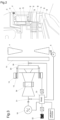
- Figure 1 shows a configuration corresponding to the essential components of an hybrid-electric aeronautical propulsion system according to the present invention.
- the figure displays two solutions for the installation of the electric machine, respectively with the rotor integrated into the power turbine and with the rotor integrated into the fan. These two installations are considered as alternatives and are illustrated in more detail below.
- Figure 2 shows some details of the preferred solution, with an electric machine integrated into the radial centrifugal power turbine.
- This solution allows for the creation of an electric machine with optimal peripheral speed, for example, from 100 to 200 m/s depending on the rotor stage on which the permanent magnets are mounted, to achieve a high power density, for instance, greater than 5 kW/kg.
- a propulsion unit with a diagonal-type centrifugal impeller 10 comprising three-dimensional blades.
- the impeller is made of aluminum alloy or composite material with carbon fibers and titanium alloy.
- the impeller swallows the air coming from a direction opposite to the direction of the aircraft's motion and imparts radial and tangential acceleration to increase its kinetic and potential energy.
- a bladed duct 19 straightens the flow in the axial direction and accelerates it to the required speed for propulsive action.
- the impeller of the propulsion unit has a peripheral speed of about 330-400 m/s and allows achieving a compression ratio of about 1.1 - 1.2.
- the blades inside the duct 19, not shown in Figure 1 are equipped with ducts fluidly connected to the exit of the radial centrifugal turbine 12 and serve as an exhaust duct up to the engine's exhaust.
- the impeller is mounted on the shaft 11 via a central hole equipped with a device for torque transmission, such as a splined profile and a centering diameter to prevent excessive imbalances during rotation.
- the hub of the impeller 10 or a rigidly connected extension 9 supports the permanent magnets of the electric machine's rotor 2, made of Neodymium.
- pre-rotation guide vanes Inlet Guide Vanes 4 designed to direct the incoming flow to the impeller to vary the impeller's characteristic in terms of flow rate and pressure.
- the "IGV" blades can rotate relative to the axis defined by the roller bearings 17 by an angle that can vary between +10° and -70°, with the 0° angle corresponding to the blade position that does not introduce variations in the flow angle, i.e., the chord lies on a meridian plane relative to the rotation axis, while the negative angle corresponds to a negative pre-rotation, discharging the impeller and decreasing its capacity to do work and pressure on the incoming airflow.
- Negative pre-rotation reduces the flow rate processed by the impeller and its pressure, i.e., the absorbed power, as the latter is proportional to the product of flow rate and pressure.
- the “IGV” blades are also axially and rotationally constrained by double-effect ball bearings 16 mounted in a frame that houses the stator of the electric machine 3 and supports a stator ogive 1 equipped with a central hole for admitting air to cool the electric machine.
- the "IGV” blades 4 are hollow to allow the passage of the electric machine's wires and are operated by a lever 5 connected with a spherical joint, not visible in Figure 1 , to an actuation and synchronization ring 6 incorporating a rack acted upon by the pinion 7 connected to an electric actuator 8, such as a stepper motor, controlled by a control system as illustrated below.
- the structure supporting the blades' bearings 17 is attached to the engine frame, which in turn is connected to the aircraft using a known technique.
- the shaft 11 connects the propulsion impeller 10 to a turbine disk 20 that supports a three-stage radial turbine 12.
- the radial outflow turbine is made up of rows of blades arranged circumferentially relative to the rotation axis and supported by rings connected with flanges to the disk 20 for the rotor rows, or to diaphragms for the stator rows.
- Figure 2 shows the radial centrifugal turbine with 3 stages, each comprising a row of stator blades and a row of rotor blades made according to a known technique, for example, as described in US patent 1915562 of 1929 .
- a first row of stator blades 27 receives the gas flow with a temperature of about 700°C from the gas generator turbine, connected rotationally to the shaft 13, and expands in the centrifugal stages until reaching a temperature of about 550°C in the last rotor blade row 26.
- the blades have a peripheral speed of about 200 m/s, generating a centrifugal force supported by two rings connected to the ends of the individual blades with a joint or a vacuum brazing process.
- One ring is connected to the turbine disk 20 via flange 28, while a second ring 22 supports the centrifugal forces generated by the rotating blades and also houses the permanent magnets 15 of the electric machine, thus constrained to rotate with the radial turbine.
- the ring 22 which can be made using laser welding or vacuum brazing techniques, incorporates a thermal shield made of insulating material 23, such as zirconium oxide, to minimize heat transmission by conduction from the blades processing combusted gases at 550°C to the Samarium Cobalt magnets, which have a maximum operating temperature of about 300°C.
- insulating material 23 such as zirconium oxide
- the electric machine's stator 14 externally to the ring 22, there is the electric machine's stator 14 positioned at a radial distance of a few tenths of a millimeter from the rotor ring 22.
- the stator formed by stamped magnetic laminations, has windings 21 connected by wires, not visible in the figures, passing through special channels inside the blades in channel 19.
- the electric machine's stator is cooled by air bled downstream of the fan at a pressure of about 1.1 BarA, at sea level, which is channeled into ducts 24 that distribute it in the stator and rotor into special channels 25 that distribute the cooling air to the magnets.
- the channels 29 are made at an angle of about 45° to the radial direction to facilitate the pumping effect due to rotation.
- Two labyrinth seals 29 pressurize the channels 25 with air at 1.1 BarA, minimizing leakage towards the blades 26 and the environment where the ring 22 rotates, equalized to ambient pressure through special channels.
- the stator 14 is powered by the generator 18 driven by the gas generator or an electrochemical storage system, or both.
- FIG 3 shows the simplified power supply and control scheme of the hybrid-electric system
- the gas generator 34 is mechanically connected to a generator 18 and fluidly connected to a radial centrifugal turbine whose stages are mounted on the disk 20.
- the generator 18 is used as a motor to start the gas generator and provide power if the system control 33, indicated as "PMAD" (Power Management & Distribution System), requires it, for example, to improve the surge margin of the gas generator compressor.
- the control system 33 manages the power flows between the various energy sources in the system, i.e., an electrochemical storage 32, the motor/generator 18, and the gas generator 34 to optimize propulsion in terms of both efficiency and effectiveness for the aircraft.
- the control system 33 controls the power supply to the electric machine integrated into the power turbine, 14 and 15, or the propulsion impeller based on speed sensors 31 and 30 and other system parameters.
- the control system 33 manages the position of the "IGV” 4 via the actuator 8 to optimize the operation of the propulsion system, for instance, to maximize the speed of the propulsion impeller 10 by reducing its absorbed power when the gas generator does not supply enough energy to the power turbine, and propulsion is mainly or entirely reliant on the electric motor.
- the "IGVs" are also controlled to optimize the thermodynamic efficiency of the power turbine at partial loads, for example, during low-speed flight, often referred to as "loitering.”
- an hydraulically actuated clutch shown in Figure 4 allows disconnecting the radial turbine's rotor stages transferring power to the propulsion unit 26 from those not connected to the electric machine.
- the turbine disk 35 transmits the torque generated by the electric machine to the propulsion unit, while the disk 36 connected to the turbine stages not mechanically connected to the electric machine is connected to disk 35 via an engaging clutch constituted by frontal teeth 37 and 38 and a single-acting hydraulic actuator 39.
- An hydraulic system not shown in the figure, supplies oil under pressure to the actuator 39, which, overcoming the return spring force, separates disk 36 from disk 35, disengaging teeth 37 and 38.
- Figure 4 shows the disengaged system, with teeth 37 and 38 unable to transmit driving torque and a radial stage braked on the support surface 40 to prevent the rotation of disk 36 and the turbine stages connected to it.
- FIG. 5 An alternative design to decouple discs 35 and 36 is shown in Figure 5 and involves using a freewheel, also known by the English name "Sprag Clutch Bearing” or one-way clutch.
- This device allows the discs to move together only when disc 36 is rotated in the direction of motion at the same speed as disc 35.
- the freewheel also incorporates the function of a radial bearing for disc 36, while specific axial bearings, 43, allow for the relative rotation of the two axially coupled discs with an elastic system 42.
- the advantages of this invention are based on an engine architecture that advantageously uses components from a turbofan to integrate electrical machines with minimal modifications, which either assist or replace the gas turbine in driving the propulsion system.
- This approach minimizes operational costs, introduces greater flexibility in use, and provides new operational capabilities, such as the ability to operate without the thermal engine.
- the simple architecture is characterized by a limited number of components and is well-suited for small power engines.
Landscapes
- Engineering & Computer Science (AREA)
- Mechanical Engineering (AREA)
- General Engineering & Computer Science (AREA)
- Chemical & Material Sciences (AREA)
- Combustion & Propulsion (AREA)
- Aviation & Aerospace Engineering (AREA)
- Structures Of Non-Positive Displacement Pumps (AREA)
- Connection Of Motors, Electrical Generators, Mechanical Devices, And The Like (AREA)
Applications Claiming Priority (1)
| Application Number | Priority Date | Filing Date | Title |
|---|---|---|---|
| IT102023000017364A IT202300017364A1 (it) | 2023-08-21 | 2023-08-21 | Sistema propulsivo ibrido-elettrico per applicazioni aeronautiche |
Publications (1)
| Publication Number | Publication Date |
|---|---|
| EP4509702A1 true EP4509702A1 (de) | 2025-02-19 |
Family
ID=90123547
Family Applications (1)
| Application Number | Title | Priority Date | Filing Date |
|---|---|---|---|
| EP24193692.1A Pending EP4509702A1 (de) | 2023-08-21 | 2024-08-08 | Hybridelektrisches antriebssystem für luftfahrtanwendungen |
Country Status (2)
| Country | Link |
|---|---|
| EP (1) | EP4509702A1 (de) |
| IT (1) | IT202300017364A1 (de) |
Cited By (1)
| Publication number | Priority date | Publication date | Assignee | Title |
|---|---|---|---|---|
| CN120135462A (zh) * | 2025-03-10 | 2025-06-13 | 西北工业大学 | 一种高紧凑热管理式燃料电池喷气发动机多模态分体混合推进系统 |
Citations (10)
| Publication number | Priority date | Publication date | Assignee | Title |
|---|---|---|---|---|
| US1915562A (en) | 1928-07-03 | 1933-06-27 | Ljungstroms Angturbin Ab | Blade ring and method of producing blade rings |
| US4193568A (en) * | 1976-07-06 | 1980-03-18 | Heuvel Norman L | Disc-type airborne vehicle and radial flow gas turbine engine used therein |
| US10378452B1 (en) * | 2018-02-26 | 2019-08-13 | The Boeing Company | Hybrid turbine jet engines and methods of operating the same |
| US10676199B2 (en) | 2017-06-12 | 2020-06-09 | General Electric Company | Propulsion system for an aircraft |
| US20200277062A1 (en) | 2019-03-01 | 2020-09-03 | Pratt & Whitney Canada Corp. | Aircraft having hybrid-electric propulsion system with electric storage located in wings |
| US20200290742A1 (en) | 2017-03-19 | 2020-09-17 | Zunum Aero, Inc. | Hybrid-electric aircraft, and methods, apparatus and systems for facilitating same |
| US10800539B2 (en) | 2016-08-19 | 2020-10-13 | General Electric Company | Propulsion engine for an aircraft |
| US10837304B2 (en) | 2016-12-13 | 2020-11-17 | General Electric Company | Hybrid-electric drive system |
| US20210179286A1 (en) | 2019-12-12 | 2021-06-17 | Rolls-Royce Plc | Aircraft hybrid propulsion system |
| US11156128B2 (en) | 2018-08-22 | 2021-10-26 | General Electric Company | Embedded electric machine |
-
2023
- 2023-08-21 IT IT102023000017364A patent/IT202300017364A1/it unknown
-
2024
- 2024-08-08 EP EP24193692.1A patent/EP4509702A1/de active Pending
Patent Citations (10)
| Publication number | Priority date | Publication date | Assignee | Title |
|---|---|---|---|---|
| US1915562A (en) | 1928-07-03 | 1933-06-27 | Ljungstroms Angturbin Ab | Blade ring and method of producing blade rings |
| US4193568A (en) * | 1976-07-06 | 1980-03-18 | Heuvel Norman L | Disc-type airborne vehicle and radial flow gas turbine engine used therein |
| US10800539B2 (en) | 2016-08-19 | 2020-10-13 | General Electric Company | Propulsion engine for an aircraft |
| US10837304B2 (en) | 2016-12-13 | 2020-11-17 | General Electric Company | Hybrid-electric drive system |
| US20200290742A1 (en) | 2017-03-19 | 2020-09-17 | Zunum Aero, Inc. | Hybrid-electric aircraft, and methods, apparatus and systems for facilitating same |
| US10676199B2 (en) | 2017-06-12 | 2020-06-09 | General Electric Company | Propulsion system for an aircraft |
| US10378452B1 (en) * | 2018-02-26 | 2019-08-13 | The Boeing Company | Hybrid turbine jet engines and methods of operating the same |
| US11156128B2 (en) | 2018-08-22 | 2021-10-26 | General Electric Company | Embedded electric machine |
| US20200277062A1 (en) | 2019-03-01 | 2020-09-03 | Pratt & Whitney Canada Corp. | Aircraft having hybrid-electric propulsion system with electric storage located in wings |
| US20210179286A1 (en) | 2019-12-12 | 2021-06-17 | Rolls-Royce Plc | Aircraft hybrid propulsion system |
Cited By (1)
| Publication number | Priority date | Publication date | Assignee | Title |
|---|---|---|---|---|
| CN120135462A (zh) * | 2025-03-10 | 2025-06-13 | 西北工业大学 | 一种高紧凑热管理式燃料电池喷气发动机多模态分体混合推进系统 |
Also Published As
| Publication number | Publication date |
|---|---|
| IT202300017364A1 (it) | 2025-02-21 |
Similar Documents
| Publication | Publication Date | Title |
|---|---|---|
| EP3964438B1 (de) | Hybrides flugzeugantriebssystem | |
| EP3530928B1 (de) | Hybridturbinenstrahltriebwerk und verfahren zum betrieb davon | |
| JP7026989B2 (ja) | ハイブリッド電気駆動システム | |
| US10717539B2 (en) | Hybrid gas-electric turbine engine | |
| US11149578B2 (en) | Propulsion system for an aircraft | |
| US20210108573A1 (en) | Gas turbine engine booster configuration and methods of operation | |
| CN115405426B (zh) | 机械驱动空气载具热管理装置 | |
| EP4296167B1 (de) | Flugzeugantriebssystem mit intermittierendem verbrennungsmotor und elektrischem übertragungssystem und verfahren zum betrieb davon | |
| US4936748A (en) | Auxiliary power source in an unducted fan gas turbine engine | |
| US10710734B2 (en) | Hybrid aircraft propulsors having electrically-driven augmentor fans | |
| US20150013306A1 (en) | Hybrid Gas Turbine Propulsion System | |
| US11905890B2 (en) | Differential gearbox assembly for a turbine engine | |
| CN112664322B (zh) | 具有离合器组件的燃气涡轮发动机 | |
| CN112377267B (zh) | 一种自冷却高速冲压空气涡轮发电机 | |
| EP3569857A1 (de) | Ummantelter elektrischer lüfter | |
| EP3543516A1 (de) | Kühlsystem und verfahren für einen elektrischen antriebsmotor | |
| US20250364872A1 (en) | Electric generator behind fan in turbine engine | |
| EP4509703A1 (de) | Flugzeugtriebwerk mit elektrischem antriebsstrang | |
| IT202300017364A1 (it) | Sistema propulsivo ibrido-elettrico per applicazioni aeronautiche | |
| EP4495390A2 (de) | Steuerung des schaufelspitzenspiels eines turbinenmotors unter verwendung einer elektrischen maschine | |
| US20240410293A1 (en) | Electric Generator Behind Fan in Turbine Engine | |
| US11643941B2 (en) | Aircraft turbine engine provided with an electrical machine | |
| EP4733566A2 (de) | Wärmeverwaltungssystem für ein flugzeugantriebssystem mit offenem rotor | |
| EP4515095A1 (de) | Hybrid-turbofan-triebwerk mit einem planetengetriebe zur leistungsmischung zwischen einem elektrischen ausgang und einem bypass-gebläse mit variabler schubkraft | |
| TWM446824U (zh) | 混合動力導風扇引擎 |
Legal Events
| Date | Code | Title | Description |
|---|---|---|---|
| PUAI | Public reference made under article 153(3) epc to a published international application that has entered the european phase |
Free format text: ORIGINAL CODE: 0009012 |
|
| STAA | Information on the status of an ep patent application or granted ep patent |
Free format text: STATUS: THE APPLICATION HAS BEEN PUBLISHED |
|
| AK | Designated contracting states |
Kind code of ref document: A1 Designated state(s): AL AT BE BG CH CY CZ DE DK EE ES FI FR GB GR HR HU IE IS IT LI LT LU LV MC ME MK MT NL NO PL PT RO RS SE SI SK SM TR |
|
| STAA | Information on the status of an ep patent application or granted ep patent |
Free format text: STATUS: REQUEST FOR EXAMINATION WAS MADE |
|
| 17P | Request for examination filed |
Effective date: 20250723 |