EP4509710A1 - Installation de gaz alimentée par le vent en mer dotée d'une capacité de stockage de chaleur - Google Patents
Installation de gaz alimentée par le vent en mer dotée d'une capacité de stockage de chaleur Download PDFInfo
- Publication number
- EP4509710A1 EP4509710A1 EP23192133.9A EP23192133A EP4509710A1 EP 4509710 A1 EP4509710 A1 EP 4509710A1 EP 23192133 A EP23192133 A EP 23192133A EP 4509710 A1 EP4509710 A1 EP 4509710A1
- Authority
- EP
- European Patent Office
- Prior art keywords
- heat
- operational
- heat storage
- thermal energy
- operational part
- Prior art date
- Legal status (The legal status is an assumption and is not a legal conclusion. Google has not performed a legal analysis and makes no representation as to the accuracy of the status listed.)
- Withdrawn
Links
Images


Classifications
-
- F—MECHANICAL ENGINEERING; LIGHTING; HEATING; WEAPONS; BLASTING
- F03—MACHINES OR ENGINES FOR LIQUIDS; WIND, SPRING, OR WEIGHT MOTORS; PRODUCING MECHANICAL POWER OR A REACTIVE PROPULSIVE THRUST, NOT OTHERWISE PROVIDED FOR
- F03D—WIND MOTORS
- F03D9/00—Adaptations of wind motors for special use; Combinations of wind motors with apparatus driven thereby; Wind motors specially adapted for installation in particular locations
- F03D9/10—Combinations of wind motors with apparatus storing energy
- F03D9/18—Combinations of wind motors with apparatus storing energy storing heat
-
- F—MECHANICAL ENGINEERING; LIGHTING; HEATING; WEAPONS; BLASTING
- F03—MACHINES OR ENGINES FOR LIQUIDS; WIND, SPRING, OR WEIGHT MOTORS; PRODUCING MECHANICAL POWER OR A REACTIVE PROPULSIVE THRUST, NOT OTHERWISE PROVIDED FOR
- F03D—WIND MOTORS
- F03D13/00—Assembly, mounting or commissioning of wind motors; Arrangements specially adapted for transporting wind motor components
- F03D13/10—Assembly of wind motors; Arrangements for erecting wind motors
- F03D13/126—Offshore
-
- F—MECHANICAL ENGINEERING; LIGHTING; HEATING; WEAPONS; BLASTING
- F03—MACHINES OR ENGINES FOR LIQUIDS; WIND, SPRING, OR WEIGHT MOTORS; PRODUCING MECHANICAL POWER OR A REACTIVE PROPULSIVE THRUST, NOT OTHERWISE PROVIDED FOR
- F03D—WIND MOTORS
- F03D13/00—Assembly, mounting or commissioning of wind motors; Arrangements specially adapted for transporting wind motor components
- F03D13/20—Arrangements for mounting or supporting wind motors; Masts or towers for wind motors
- F03D13/25—Arrangements for mounting or supporting wind motors; Masts or towers for wind motors specially adapted for offshore installation
-
- F—MECHANICAL ENGINEERING; LIGHTING; HEATING; WEAPONS; BLASTING
- F05—INDEXING SCHEMES RELATING TO ENGINES OR PUMPS IN VARIOUS SUBCLASSES OF CLASSES F01-F04
- F05B—INDEXING SCHEME RELATING TO WIND, SPRING, WEIGHT, INERTIA OR LIKE MOTORS, TO MACHINES OR ENGINES FOR LIQUIDS COVERED BY SUBCLASSES F03B, F03D AND F03G
- F05B2220/00—Application
- F05B2220/61—Application for hydrogen and/or oxygen production
-
- F—MECHANICAL ENGINEERING; LIGHTING; HEATING; WEAPONS; BLASTING
- F05—INDEXING SCHEMES RELATING TO ENGINES OR PUMPS IN VARIOUS SUBCLASSES OF CLASSES F01-F04
- F05B—INDEXING SCHEME RELATING TO WIND, SPRING, WEIGHT, INERTIA OR LIKE MOTORS, TO MACHINES OR ENGINES FOR LIQUIDS COVERED BY SUBCLASSES F03B, F03D AND F03G
- F05B2240/00—Components
- F05B2240/90—Mounting on supporting structures or systems
- F05B2240/95—Mounting on supporting structures or systems offshore
-
- F—MECHANICAL ENGINEERING; LIGHTING; HEATING; WEAPONS; BLASTING
- F05—INDEXING SCHEMES RELATING TO ENGINES OR PUMPS IN VARIOUS SUBCLASSES OF CLASSES F01-F04
- F05B—INDEXING SCHEME RELATING TO WIND, SPRING, WEIGHT, INERTIA OR LIKE MOTORS, TO MACHINES OR ENGINES FOR LIQUIDS COVERED BY SUBCLASSES F03B, F03D AND F03G
- F05B2260/00—Function
- F05B2260/20—Heat transfer, e.g. cooling
-
- Y—GENERAL TAGGING OF NEW TECHNOLOGICAL DEVELOPMENTS; GENERAL TAGGING OF CROSS-SECTIONAL TECHNOLOGIES SPANNING OVER SEVERAL SECTIONS OF THE IPC; TECHNICAL SUBJECTS COVERED BY FORMER USPC CROSS-REFERENCE ART COLLECTIONS [XRACs] AND DIGESTS
- Y02—TECHNOLOGIES OR APPLICATIONS FOR MITIGATION OR ADAPTATION AGAINST CLIMATE CHANGE
- Y02E—REDUCTION OF GREENHOUSE GAS [GHG] EMISSIONS, RELATED TO ENERGY GENERATION, TRANSMISSION OR DISTRIBUTION
- Y02E10/00—Energy generation through renewable energy sources
- Y02E10/70—Wind energy
- Y02E10/72—Wind turbines with rotation axis in wind direction
Definitions
- the invention relates to offshore wind turbine powered plants such as for hydrogen production with improved readiness for operation when the wind is back after a period of no wind and power production.
- Scope of the present invention is to provide a solution aiding the start-up of the plant after a standby period with no or insufficient wind and improve energy efficiency.
- the invention includes introducing a system comprising a wind turbine 1 powering an operational part producing excess heat when operating, wherein the system further includes a heat transferring system comprising a heat storage in heat exchange connection to the operational part, and adapted to store at least a part of the excess heat produced by the operational part as thermal energy in a cooling state of the heat transferring system, and to direct the thermal energy to the heat transferring system to heat the operational part in a heating state when the operational part is in standby.
- a system comprising a wind turbine 1 powering an operational part producing excess heat when operating
- the system further includes a heat transferring system comprising a heat storage in heat exchange connection to the operational part, and adapted to store at least a part of the excess heat produced by the operational part as thermal energy in a cooling state of the heat transferring system, and to direct the thermal energy to the heat transferring system to heat the operational part in a heating state when the operational part is in standby.
- the heat storage may be positioned within the foundation of the tower and/or within the tower itself.
- the heat storage may at least partly be positioned in or in contact with the ocean water.
- the heat transfer may be accomplished through the circulation of a heat transferring fluid at least coming in heat exchange contact with the heat storage and operational parts.
- the heat storage may comprise multiple individual heat storage tanks.
- the heat storage may be positioned to be fully or at least partly submersed in water. This could be it being positioned in the ocean, or the ocean having fluid communication or access to its storage position, such as inside the tower or foundation.
- the heat storage may be installed on an airtight deck below the platform, within the tower or tower foundation.
- a heat exchanger adapted to regulate the temperature within the heat storage.
- the heat storage may comprise a media within to store thermal energy, such as a liquid like water, solid materials with a high capacity to maintain thermal energy for a substantial period, e.g. in the form of pebbles, granules, etc.
- thermal energy such as a liquid like water, solid materials with a high capacity to maintain thermal energy for a substantial period, e.g. in the form of pebbles, granules, etc.
- the present invention further relates to a method to control the temperature of operational parts powered by a wind turbine, wherein the method includes to control a heat transferring system in a cooling state where excess heat is transferred via the heat transferring system from the operational parts to a heating storage when the operational parts are in operational state, and when the operational parts are in standby, via the heat transferring system use stored thermal energy in the heat storage to heat the operational parts in a heating state.
- the method may be operated on the system according to any of the previous embodiments.
- the operational parts may be electrolyzers for hydrogen production.
- the wind turbine may be positioned offshore, and/or not being connected to the grid.
- By not being connected to the grid means the transmission grid, such that it cannot drag on power from the grid during low wind periods creating insufficient power to run the operational parts and other devices like auxiliaries, the standby periods.
- the method may further include to pass a heat transferring fluid between the operational parts (and/or auxiliaries or other power demanding devices) and the heating storage.
- the heat transferring fluid may be flowing in one direction during cooling state and the reverse direction during heating state.
- the method may include to use cooling state when a temperature measured in connection with the heating storage is lower than a temperature measured in relation with the operational parts, and to use heating state when a temperature measured in connection with the heating storage is higher than a temperature measured in relation with the operational parts.
- the heat transferring fluid passing the heat storage at a regulated rate during operation of the operational parts could be installed to measure temperature(s) within the heat storage and control the transfer of thermal energy to the heat reservoir to maintain the temperature(s) within given ranges, such as by controlling the flow of heat transferring fluid to (and from) the thermal reservoir. In an additional, or alternative, embodiment, if the temperature drops below a given minimum threshold then more thermal energy is directed to the heat storage tanks until a given temperature is reached.
- the present invention thus introduces the means and method according to any of the preceding embodiments to use thermal energy stored as heat in the heat storage to maintain the temperatures of these devices and fluid(s) during standby periods.
- the present invention may further relate to a system comprising a wind turbine powering an operational part producing excess heat when operating, wherein the system further includes a heat transferring system in heat exchange connection to the operational part and adapted to transport thermal energy from the operational part to a heat exchanger submersed in the water.
- submersed in the water may mean being positioned in the ocean water or in water in direct exchange with ocean water. In this manner the ocean water forms pool to absorb heat from the heat exchanger.
- the heat storage may be installed on an airtight deck below the platform, within the tower or tower foundation to store at least a part of the excess heat produced by the operational part as thermal energy in a cooling state of the heat transferring system, and to direct the thermal energy to the heat transferring system to heat the operational part in a heating state when the operational part is in standby, and where the heat transferring system further connects the heat storage to the heat exchanger to regulate the temperature within the heat storage.
- This system with the heat exchanger and/or heat storage installed on an airtight deck may further comprise the features of any of the previous embodiments and/or operating according to the method of any of the previous embodiments.
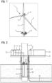
- Figure 1 shows an embodiment wind turbine 1 positioned offshore in the water, such as the ocean.
- the wind turbine 1 comprises a tower 2 mounted on a non-depicted fundament.
- a nacelle 3 is arranged on top of the tower 2.
- the wind turbine 1 further comprises a wind rotor 5 having two, three or more blades 4.
- the wind rotor 5 is rotatable around a longitudinal rotation axis.
- the wind turbine 1 comprises an electric generator.
- a platform 10 is positioned at the tower 2.
- the position of the platform 10 at the tower 2 could be such that it is generally above water despite waves and tides.
- the platform 6 is adapted for plants comprising operational parts. These could be positioned within containers 7 positioned and optionally fixed on the platform 6 surface. In a non-exclusive manner the containers 7 thus could comprise operational parts such as electrolyzers 8 for a hydrogen production plant, but could be other systems e.g., CO2 extraction machines. In the following the operational parts (in containers or positioned elsewhere) are exampled as being hydrogen producing plants.
- Figure 2 shows an embodiment of the present invention illustrating the lower part of the tower 2 mounted on a fundament.
- the platform 6 comprising operational parts, such as electrolyzers 8 and other associated and required devices like e.g. a gas treatment system 9, a water treatment System 10, energy back-up System 11, DOHP system control and SCADA 12, project specific features and equipment 13, sea water intake 14 to feed the system with water etc.
- operational parts such as electrolyzers 8 and other associated and required devices like e.g. a gas treatment system 9, a water treatment System 10, energy back-up System 11, DOHP system control and SCADA 12, project specific features and equipment 13, sea water intake 14 to feed the system with water etc.
- heat storage 20 adapted to store heat, or thermal energy, and may be formed as an isolated tank.
- the thermal energy is stored in the form of a hot, or thermal carrying, liquid like water.
- heat in general, or in the example of hot water refers to having a higher temperature than the ambient temperature and the e.g. ocean water. Its temperature further may be at least at the level of an operational temperature of the e.g. electrolyzers 8, such as a defined level or a level ensuring a given efficiency or required temperature of process water.
- the heat storage tank 20 may comprise multiple individual heat storage tanks 21, 22, where two are shown in the figure.
- the heat storage 20, and optional individual heat storage tanks 21, 22, are formed with heat storage (tank) tops 23 that can be opened for cleaning or inspection purposes.
- Electrolyzers producing e.g. hydrogen usually generate a significant amount of heat, and thus need to be cooled, and for this purpose the system of the present invention includes a heat transferring system.
- the seabed distributes the heat in an even distribution in the environment. This avoids marine growth on the pipe 24.
- the heat transferring system also includes the heat reservoir 20, 21, 22.
- the media for the heat transportation in the pipe 24 could be water (for example Sweetwater with no organism) or potentially glycol or any other suitable fluid.
- water for example Sweetwater with no organism
- glycol any other suitable fluid.
- At least a (possible controllable) fraction is by any suitable means directed to the heat storage 20, 21, 22.
- the valve could be controlled by a controller and/or actuator of any kind e.g. automatically by wireless or wired means. Alternatively, it could be manually operated.
- Thermal energy may be stored within heat storage 20, 21, 22 in any form, and may simply be the e.g. heat transferring fluid circulated to cool the electrolyzers 8 during operation.
- the state of operation where heat, or thermal energy, is transferred from the e.g. electrolyzers 8 to the heat storage 20, 21, 22 is referred to as the heat transferring system being operated in a cooling state.
- the idea of the present invention in its basic is to store excess heat from the plants like electrolyzers 8 and use it to control the temperature in the heat storage 20, 21, 22.
- the heat transferring fluid constantly be passing the heat storage 20, 21, 22 at a regulated rate during operation of the e.g. electrolyzers 8.
- Temperature sensors could be installed to measure temperature(s) within the heat storage 20, 21, 22 and control the transfer of thermal energy to the heat reservoir 20, 21, 22 to maintain the temperature(s) within given ranges, such as by controlling the flow of heat transferring fluid to (and from) the thermal reservoir 20, 21, 22.
- if the temperature drops below a given minimum threshold then more thermal energy is directed to the heat storage tanks 20, 21, 22 until a given temperature is reached.
- the excess heat from the electrolyzers 8 may be feed to the heat storage 20, 21, 22 at their bottoms, or lower section since heat tends to flow upwards.
- heat when heat is to be extracted e.g. to maintain electrolyzers 8 temperature during standby, it could be extracted from the top, or upper part, of the heat storage 20, 21, 22.
- the heat storage 20, 21, 22 as illustrated may be positioned within the foundation of the tower 2 as illustrated, and/or within the tower 2 itself. In one embodiment it is positioned in e.g. the ocean water such that it more or less floats. This offers a suitable position such as due to the weight of the heat storage 20, 21, 22 and frees up space.
- the heat storage 20, 21, 22 may further be formed as or positioned inside insulated tanks keep the heat storage media hot over a long standby period.
- the temperature may be in the range of 40-90 degrees, or 50-80 degrees, or about 60-70 degrees or about 60 degrees.
- the heat transferring system In the periods where sufficient power is available the heat transferring system thus runs in the cooling state, where the operational parts are actively operating. In this state it is expected the temperature(s) in the heat storage 20, 21, 22 is lower than the temperature of the operational parts.
- the present invention introduces a heating state where thermal energy, or heat, is transferred from the heat storage 20, 21, 22 to the operational parts (like electrolyzers 8, and optionally other relevant devices parts of the system, like 9-13 and any auxiliaries, to maintain a given minimum temperature.
- this is achieved by reversing the cooling means of the electrolyzer 8 (the cooling state). For example, if during operational state of the electrolyzers 8 is circulated to remove excess heat, in the standby, a heating state is introduced where the stored thermal energy in the heat storage 20, 21, 22 is directed to the e.g. electrolyzer 8 and other devices and auxiliaries by the heat transferring fluid.
- the heat transferring fluid in the heating state is simply used to heat rather than to cool.
- a small power supply such as a battery would still be needed for this operation, however the needed power is be significantly lower as the heat is already available, thus enabling the installation of a significantly smaller battery.
- the heat from the heat storage 20, 21, 22 is be used to keep the operational parts, equipment 9-13 and/or other auxiliaries in operating temperature over a long period without other energy than e.g. circulation pump etc. (with a low consumption for standby).
- Figure 3 illustrates an embodiment similar to figure 2 , but where boilers 30 are installed within the heat storage 20, 21, 22, such as within each of the individual tanks 21, 22.
- Figure 4 illustrates an embodiment where the heat storage tank 20 is installed on an airtight deck 40 below the platform 6, but possible within the tower 2 or tower 2 foundation, and possible above water level (at a substantially dry position).
- a heat exchanger 41 such as in the form of a pipe spiral in the foundation.
- heat is directed from an upper part of the heat storage 20 to the heat exchanger 41. In the heat exchanger 41 it is cooled and then directed back to the heat storage 20 at a lower section.
- heat may thus be exchanged with the ocean, using this as a cooling 'reservoir' .
- the figure further illustrates systems of pipes 50, 51 forming part of the heat transferring system according to embodiments.
- One system of pipes 50 connected to the lower part of the heat storage 20 and the other system of pipes 51 is connected at an upper or middle part of the heat storage 20.
- the system of this embodiment is adapted to ensure a maximum temperature in the heat reservoir 20, still maintaining the temperature within a given range.
- Figure 5 illustrates an embodiment relevant to any of the previous embodiments, where the heat storage 20, 21, 22 includes solid materials 60 with a high capacity to maintain thermal energy for a substantial period, e.g. in the form of pebbles, granules, etc.
- a heat transferring fluid then may be circulated to the operational parts, and thus passes the materials 60 to give off thermal energy (respectively collect thermal energy).
Landscapes
- Engineering & Computer Science (AREA)
- Life Sciences & Earth Sciences (AREA)
- Sustainable Development (AREA)
- Sustainable Energy (AREA)
- Chemical & Material Sciences (AREA)
- Combustion & Propulsion (AREA)
- Mechanical Engineering (AREA)
- General Engineering & Computer Science (AREA)
- Power Engineering (AREA)
- Wind Motors (AREA)
- Engine Equipment That Uses Special Cycles (AREA)
Priority Applications (2)
| Application Number | Priority Date | Filing Date | Title |
|---|---|---|---|
| EP23192133.9A EP4509710A1 (fr) | 2023-08-18 | 2023-08-18 | Installation de gaz alimentée par le vent en mer dotée d'une capacité de stockage de chaleur |
| PCT/EP2024/067896 WO2025040288A1 (fr) | 2023-08-18 | 2024-06-26 | Raffinerie de gaz éolien en mer dotée d'une capacité de stockage de chaleur |
Applications Claiming Priority (1)
| Application Number | Priority Date | Filing Date | Title |
|---|---|---|---|
| EP23192133.9A EP4509710A1 (fr) | 2023-08-18 | 2023-08-18 | Installation de gaz alimentée par le vent en mer dotée d'une capacité de stockage de chaleur |
Publications (1)
| Publication Number | Publication Date |
|---|---|
| EP4509710A1 true EP4509710A1 (fr) | 2025-02-19 |
Family
ID=87747939
Family Applications (1)
| Application Number | Title | Priority Date | Filing Date |
|---|---|---|---|
| EP23192133.9A Withdrawn EP4509710A1 (fr) | 2023-08-18 | 2023-08-18 | Installation de gaz alimentée par le vent en mer dotée d'une capacité de stockage de chaleur |
Country Status (2)
| Country | Link |
|---|---|
| EP (1) | EP4509710A1 (fr) |
| WO (1) | WO2025040288A1 (fr) |
Citations (3)
| Publication number | Priority date | Publication date | Assignee | Title |
|---|---|---|---|---|
| US20090212560A1 (en) * | 2006-11-03 | 2009-08-27 | Vestas Wind Systems A/S | Heating System, Wind Turbine Or Wind Park, Method For Utilizing Surplus Heat Of One Or More Wind Turbine Components And Use Hereof |
| US20090289461A1 (en) * | 2007-01-31 | 2009-11-26 | Gerner Larsen | Wind Energy Converter With Dehumidifier |
| EP3936717A1 (fr) * | 2020-07-10 | 2022-01-12 | Vattenfall AB | Parc éolien comportant une tuyauterie de récupération de chaleur |
-
2023
- 2023-08-18 EP EP23192133.9A patent/EP4509710A1/fr not_active Withdrawn
-
2024
- 2024-06-26 WO PCT/EP2024/067896 patent/WO2025040288A1/fr active Pending
Patent Citations (3)
| Publication number | Priority date | Publication date | Assignee | Title |
|---|---|---|---|---|
| US20090212560A1 (en) * | 2006-11-03 | 2009-08-27 | Vestas Wind Systems A/S | Heating System, Wind Turbine Or Wind Park, Method For Utilizing Surplus Heat Of One Or More Wind Turbine Components And Use Hereof |
| US20090289461A1 (en) * | 2007-01-31 | 2009-11-26 | Gerner Larsen | Wind Energy Converter With Dehumidifier |
| EP3936717A1 (fr) * | 2020-07-10 | 2022-01-12 | Vattenfall AB | Parc éolien comportant une tuyauterie de récupération de chaleur |
Also Published As
| Publication number | Publication date |
|---|---|
| WO2025040288A1 (fr) | 2025-02-27 |
Similar Documents
| Publication | Publication Date | Title |
|---|---|---|
| AU2007315397B2 (en) | Heating system, wind turbine or wind park, method for utilizing surplus heat of one or more wind turbine components and use hereof | |
| US20240167457A1 (en) | Offshore renewable energy power station | |
| US10344741B2 (en) | Hydro-pneumatic energy storage system | |
| EP2914919B1 (fr) | Procédé d'exploitation d'un agencement destiné au stockage d'énergie thermique | |
| EP2012366A2 (fr) | Système photovoltaïque à efficacité améliorée et procédé incrémentiel de la production d'énergie électrique d'au moins un module solaire thermo-photovoltaïque | |
| US20150321739A1 (en) | Marine subsurface data center vessel | |
| JP2009138555A (ja) | 風力発電装置 | |
| US7328578B1 (en) | Integrated OTEC platform | |
| EP2279334A1 (fr) | Centrale d'énergie solaire thermique | |
| KR102114397B1 (ko) | 히트 펌프를 이용한 해양 온도차 발전 시스템 | |
| CN118128710A (zh) | 一种可调式海上风力发电机组冷却系统 | |
| WO2011073628A1 (fr) | Système et procédé de chauffage ou de refroidissement | |
| US20210199091A1 (en) | Wind turbine electric generation, heat transfer and heat storage systems and methods | |
| WO2025040288A1 (fr) | Raffinerie de gaz éolien en mer dotée d'une capacité de stockage de chaleur | |
| CN118816610A (zh) | 利用海、湖、水库水下空间跨季节水体储热的低碳供热系统 | |
| WO2018069396A1 (fr) | Accumulateur d'énergie thermique | |
| EP4495499B1 (fr) | Installation flottante pour générer de la chaleur et/ou du refroidissement et pour la distribution directe de celle-ci ou pour la connexion à un système de chauffage et/ou de refroidissement urbain | |
| CN220539777U (zh) | 一种自控海水温差发电系统 | |
| McGowan et al. | Gulf-Stream-Based, Ocean-Thermal Power Plants | |
| KR20200003602A (ko) | 해상 플랫폼과 이의 에너지 저장 및 회수방법 | |
| JP2005282361A (ja) | 動力産出装置 | |
| NO20200447A1 (en) | Thermal Energy Storage Device | |
| TR2024010676A1 (tr) | Soğutma özelli̇kleri̇ i̇yi̇leşti̇ri̇lmi̇ş bi̇r yüzer enerji̇ si̇stemi̇ |
Legal Events
| Date | Code | Title | Description |
|---|---|---|---|
| PUAI | Public reference made under article 153(3) epc to a published international application that has entered the european phase |
Free format text: ORIGINAL CODE: 0009012 |
|
| STAA | Information on the status of an ep patent application or granted ep patent |
Free format text: STATUS: THE APPLICATION HAS BEEN PUBLISHED |
|
| AK | Designated contracting states |
Kind code of ref document: A1 Designated state(s): AL AT BE BG CH CY CZ DE DK EE ES FI FR GB GR HR HU IE IS IT LI LT LU LV MC ME MK MT NL NO PL PT RO RS SE SI SK SM TR |
|
| STAA | Information on the status of an ep patent application or granted ep patent |
Free format text: STATUS: THE APPLICATION IS DEEMED TO BE WITHDRAWN |
|
| 18D | Application deemed to be withdrawn |
Effective date: 20250820 |