EP4509729A1 - Ensemble boulon d'expansion multifonctionnel - Google Patents
Ensemble boulon d'expansion multifonctionnel Download PDFInfo
- Publication number
- EP4509729A1 EP4509729A1 EP23201279.9A EP23201279A EP4509729A1 EP 4509729 A1 EP4509729 A1 EP 4509729A1 EP 23201279 A EP23201279 A EP 23201279A EP 4509729 A1 EP4509729 A1 EP 4509729A1
- Authority
- EP
- European Patent Office
- Prior art keywords
- screw rod
- sleeve
- bolt assembly
- expansion bolt
- connecting member
- Prior art date
- Legal status (The legal status is an assumption and is not a legal conclusion. Google has not performed a legal analysis and makes no representation as to the accuracy of the status listed.)
- Withdrawn
Links
Images




Classifications
-
- F—MECHANICAL ENGINEERING; LIGHTING; HEATING; WEAPONS; BLASTING
- F16—ENGINEERING ELEMENTS AND UNITS; GENERAL MEASURES FOR PRODUCING AND MAINTAINING EFFECTIVE FUNCTIONING OF MACHINES OR INSTALLATIONS; THERMAL INSULATION IN GENERAL
- F16B—DEVICES FOR FASTENING OR SECURING CONSTRUCTIONAL ELEMENTS OR MACHINE PARTS TOGETHER, e.g. NAILS, BOLTS, CIRCLIPS, CLAMPS, CLIPS OR WEDGES; JOINTS OR JOINTING
- F16B13/00—Dowels or other devices fastened in walls or the like by inserting them in holes made therein for that purpose
- F16B13/04—Dowels or other devices fastened in walls or the like by inserting them in holes made therein for that purpose with parts gripping in the hole or behind the reverse side of the wall after inserting from the front
- F16B13/06—Dowels or other devices fastened in walls or the like by inserting them in holes made therein for that purpose with parts gripping in the hole or behind the reverse side of the wall after inserting from the front combined with expanding sleeve
- F16B13/063—Dowels or other devices fastened in walls or the like by inserting them in holes made therein for that purpose with parts gripping in the hole or behind the reverse side of the wall after inserting from the front combined with expanding sleeve by the use of an expander
- F16B13/065—Dowels or other devices fastened in walls or the like by inserting them in holes made therein for that purpose with parts gripping in the hole or behind the reverse side of the wall after inserting from the front combined with expanding sleeve by the use of an expander fastened by extracting the screw, nail or the like
-
- F—MECHANICAL ENGINEERING; LIGHTING; HEATING; WEAPONS; BLASTING
- F16—ENGINEERING ELEMENTS AND UNITS; GENERAL MEASURES FOR PRODUCING AND MAINTAINING EFFECTIVE FUNCTIONING OF MACHINES OR INSTALLATIONS; THERMAL INSULATION IN GENERAL
- F16B—DEVICES FOR FASTENING OR SECURING CONSTRUCTIONAL ELEMENTS OR MACHINE PARTS TOGETHER, e.g. NAILS, BOLTS, CIRCLIPS, CLAMPS, CLIPS OR WEDGES; JOINTS OR JOINTING
- F16B13/00—Dowels or other devices fastened in walls or the like by inserting them in holes made therein for that purpose
- F16B13/04—Dowels or other devices fastened in walls or the like by inserting them in holes made therein for that purpose with parts gripping in the hole or behind the reverse side of the wall after inserting from the front
- F16B13/06—Dowels or other devices fastened in walls or the like by inserting them in holes made therein for that purpose with parts gripping in the hole or behind the reverse side of the wall after inserting from the front combined with expanding sleeve
- F16B13/063—Dowels or other devices fastened in walls or the like by inserting them in holes made therein for that purpose with parts gripping in the hole or behind the reverse side of the wall after inserting from the front combined with expanding sleeve by the use of an expander
- F16B13/066—Dowels or other devices fastened in walls or the like by inserting them in holes made therein for that purpose with parts gripping in the hole or behind the reverse side of the wall after inserting from the front combined with expanding sleeve by the use of an expander fastened by extracting a separate expander-part, actuated by the screw, nail or the like
Definitions
- the present invention relates to a multifunctional expansion bolt assembly and, more particularly, to an expansion bolt assembly capable of preventing idle rotation of the bolt and providing connection with various bolts or nuts.
- a conventional expansion bolt assembly includes a screw rod placed into a sleeve.
- the screw rod includes a conic head.
- the screw rod and the sleeve are inserted into a hole of a fixture.
- a threaded portion of the screw rod protrudes beyond a surface of the fixture.
- the protruded threaded portion can be in threading connection with a nut, such that a to-be-fixed object can be fixed to the fixture.
- the conventional expansion bolt assembly is generally used on an outer wall of a building, such as a sign or a frame for an air conditioner.
- the threaded portion of the screw rod of the conventional expansion bolt assembly protrudes beyond the surface of the fixture, such that the to-be-fixed object can only be fixed by the nut to the surface of the fixture.
- the fixing way cannot be changed and, thus, cannot fulfill different needs to achieve diverse fixing ways.
- the screw rod placed into the sleeve has a single size
- the worker when it is desired to change the protruding length of the screw rod or the diameter of the threaded portion, the worker must grind the protruded screw rod already inserted and then insert an expansion bolt assembly of a different specification to a location adjacent to the original screw rod, which is time-consuming.
- the newly inserted expansion bolt assembly is adjacent to the original already-inserted expansion bolt assembly, such that the newly inserted expansion bolt assembly may have insufficient adhesion.
- the term "a”, “an” or “one” for describing the number of the elements and members of the present invention is used for convenience, provides the general meaning of the scope of the present invention, and should be interpreted to include one or at least one. Furthermore, unless explicitly indicated otherwise, the concept of a single component also includes the case of plural components.
- a multifunctional expansion bolt assembly includes a sleeve, a screw rod, and a connecting member.
- the sleeve includes opposite first and second ends.
- a hollow body is formed between the first end and the second end of the sleeve.
- the second end of the sleeve includes at least one open groove.
- the at least one open groove has an opening on an end face of the second end of the sleeve.
- the screw rod includes opposite first and second ends.
- the first end of the screw rod includes a threaded portion. At least a portion of the threaded portion protrudes beyond the first end of the sleeve.
- the second end of the screw rod includes a conic portion having gradually increasing diameters towards an end face of the second end of the screw rod.
- the conic portion has a maximal diameter greater than an inner diameter of the second end of the sleeve.
- the screw rod includes at least one engaging portion.
- the screw rod has non-circular cross section at the at least one engaging portion.
- the at least one engaging portion engages with the at least one open groove.
- the connecting member includes opposite first and second ends.
- the second end of the connecting member has an inner threading in threading connection with a portion of the threaded portion of the screw rod.
- the first end of the connecting member has a connecting portion.
- the multifunctional expansion bolt assembly according to the present invention since the second end of the sleeve has at least one open groove and the screw rod has at least one engaging portion engaged with the at least one open groove, relative rotation between the screw rod and the sleeve is prevented to thereby permit easy installation. Furthermore, the multifunctional expansion bolt assembly according to the present invention permits replacement of connecting members of different structures according to different needs in use, achieving diverse fixing ways.
- the sleeve includes an outer periphery having a rough portion. Therefore, the sleeve and the inner wall of the fixture have a better adhesion effect therebetween.
- the at least one engaging portion includes at least one protrusion protruding radially outward from an outer periphery of the screw rod.
- the number of the at least one protrusion is identical to the number of the at least one open groove. Therefore, the screw rod and the sleeve can be easily engaged, and relative rotation can be prevented.
- the at least one protrusion extends to the conic portion. Therefore, each engaging portion in the form of a protrusion can engage with an associated open groove, thereby preventing relative rotation between the screw rod and the sleeve.
- the cross section of the conic portion is a polygon.
- the number of sides of the polygon is identical to the number of the at least one open groove.
- Each corner of the polygon forms the engaging portion. Therefore, the engaging portion at each corner of the polygon can engage with an associated open groove to prevent relative rotation between the screw rod and the sleeve.
- the first end of the connecting member has a driving portion. Therefore, the driving portion can be used to drive the connecting member to rotate, such that the multifunctional expansion bolt assembly can tightly engage with a hole of a fixture.
- the multifunctional expansion bolt assembly may further include an external coupling member.
- the external coupling member includes a threaded portion and an outer connecting portion.
- the threaded portion of the external coupling member is in threading connection with the inner threading of the connecting member.
- the outer connecting portion is configured to couple with a to-be-fixed object. Therefore, the outer connecting portion may engage with a to-be-fixed object.
- the connecting portion of the connecting member is in the form of a threading integrally formed with the inner threading. Therefore, the inner threading of the connecting member can directly be in threading connection with an external coupling member, and the external coupling member can engage with a to-be-fixed object.
- the connecting portion of the connecting member is a screw hole having an inner threading, and an inner diameter of the connecting portion is different from a diameter of the inner threading of the connecting member. Therefore, different connecting members of different hole diameters can be replaced according to different needs in use, and the connecting portion can engage with a to-be-fixed object.
- the connecting portion of the connecting member is a stud having an outer threading. Therefore, different connecting members of different outer diameters and different threadings can be replaced according to different needs in use to thereby fix a to-be-fixed object.
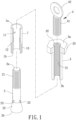
- a multifunctional expansion bolt assembly of a first embodiment according to the present invention includes a sleeve 1, a screw rod 2, and a connecting member 3.
- the screw rod 2 extends through a hollow body 11 of the sleeve 1.
- the connecting member 3 can be in threading connection with the screw rod 2.
- the sleeve 1 includes opposite first and second ends 1a and 1b.
- the hollow body 11 is formed between the first end 1a and the second end 1b of the sleeve 1.
- the second end 1b includes at least one open groove 12.
- the at least one open groove 12 has an opening on an end face of the second end 1b of the sleeve 1, such that the second end 1b of the sleeve 1 may expand and deform.
- the sleeve 1 includes four open grooves 12 which are equi-angularly disposed on the second end 1b to permit easier expansion and deformation of the sleeve 1 and more uniform deformation of the sleeve 1.
- the outer surface of the sleeve 1 has a rough portion 13 which may be in the form of embossment, protrusive ridges, etc., such that the sleeve 1 and an inner wall of a fixture may have better adhesion therebetween.
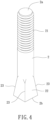
- the screw rod 2 includes opposite first and second ends 2a and 2b.
- the first end 2a of the screw rod 2 includes a threaded portion 21, such that the screw rod 2 can extend through the hollow body 11 of the sleeve 1, and at least a portion of the threaded portion 21 protrudes beyond the first end 1a of the sleeve 1.
- the second end 2b of the screw rod 2 includes a conic portion 22 having gradually increasing diameters towards an end face of the second end 2b of the screw rod 2.
- the conic portion 22 has a maximal diameter greater than an inner diameter of the second end 1b of the sleeve 1.
- the cross section of the conic portion 22 may be polygonal or circular. The present invention is not limited in this regard.
- the screw rod 2 includes at least one engaging portion 23, and the cross-section of the screw rod 2 at the at least one engaging portion 23 is non-circular.
- the at least one engaging portion 23 can engage with the at least one open groove 12.
- both the cross section of the conic portion 22 and the cross section of the inner wall of the sleeve 1 are circular.
- the at least one engaging portion 23 may be in the form of at least one protrusion protruding radially outward from an outer periphery of the screw rod 2, and the at least one engaging portion 23 in the form of a protrusion may extend to the conic portion 22 (not shown).
- the present invention is not limited in this regard.
- the number of the at least one protrusion is identical to a number of the at least one open groove 12, such that each engaging portion 23 in the form of a protrusion can engage with an associated open groove 12, thereby preventing relative rotation between the screw rod 2 and the sleeve 1.
- the cross section of the conic portion 22 is polygonal, and the number of the sides of the polygon is the same as the number of the open grooves 12.
- Each corner of the polygon forms an engaging portion 23 which is aligned with an associated open groove 12.
- each engaging portion 23 at the corner can engage with an associated open groove 12 to prevent relative rotation between the screw rod 2 and the sleeve 1, which can be appreciated by one having ordinary skill in the art, and detail description is not set forth to avoid redundancy.
- the connecting member 3 includes opposite first and second ends 3a and 3b.
- the second end 3b of the connecting member 3 has an inner threading 31 in threading connection with a portion of the threaded portion 21 of the screw rod 2.
- the first end 3a of the connecting member 3 has a connecting portion 32.
- the connecting portion 32 of the connecting member 3 is in the form of a threading integrally formed with the inner threading 31.
- the connecting member 3 may be in partial threading connection with the threaded portion 21 of the screw rod 2 protruding beyond the sleeve 1 by the inner threading 31 of the second end 3b, such that the inner threading 31 of the connecting member 3 has a section N not in threading connection with the screw rod 2, and the section N may be in threading connection with an external coupling member 4.
- the first end 3a of the connecting member 3 has a driving portion 33 which may be in the form of a nut.
- the multifunctional expansion bolt assembly according to the present invention may further include an external coupling member 4.
- the external coupling member 4 includes a threaded portion 41 and an outer connecting portion 42.
- the threaded portion 41 may be in threading connection with the inner threading 31 of the connecting member 3. Namely, the threaded portion 41 may be in threading connection with the above section N not in threading connection with the screw rod 2 (as shown in FIG. 2 ), and the outer connecting portion 42 may couple with a to-be-fixed object.
- FIG. 3 shows an example of use of the multifunctional expansion bolt assembly of the first embodiment according to the present invention.
- a fixture F is drilled to form a hole H, and the second ends 1b, 2b, 3b of the sleeve 1, the screw rod 2, and the connecting member 3 are placed into the hole H.
- the connecting member 3 is rotated via the driving portion 33 to move the conic head 22 of the screw rod 2 upward, as indicated by the arrow head. Since the engaging portions 23 of the screw rod 2 respectively engage with the open grooves 12, the conic portion 22 urges the second end 1b of the sleeve 1 to expand radially outward until the connecting member 3 cannot be rotated any more, thereby securely fixing the sleeve 1 in the hole H.
- the section N of the connecting member 3 not in threading connection with the screw rod 2 can be in threading connection with the threaded portion 41 of the external coupling member 4, such that the external coupling member 4 can fix a to-be-fixed object to the fixture F.
- the connecting member 5 includes an inner threading 51 and a connecting portion 52.
- the inner threading 51 can be in threading connection with the threaded portion 21 of the screw rod 2, and the connecting member 5 may have different connecting portions 52 for engaging with a to-be-fixed object.
- the connecting portion 52 may be in the form of a screw hole having an inner threading, and a diameter of the connecting portion 52 in the form of a screw hole may have various sizes. Therefore, connecting members 5 of different hole diameters may be available to permit replacement according to different needs in use.
- the inner diameter of the connecting portion 52 is different from the diameter of the inner threading 51 of the connecting member 5. The difference may exist in the major diameter, the minor diameter or the pitch of the threadings, according to different needs in use.
- the worker may remove the connecting member 3 and the external coupling member 4 and then engage another connecting member 6 with the screw rod 2.
- the connecting member 6 includes an inner threading 61 and a connecting portion 62.
- the inner threading 61 can be in threading connection with the threaded portion 21 of the screw rod 2, and the connecting member 6 may have different connecting portions 62 for engaging with a to-be-fixed object.
- the connecting portion 62 may be in the form of a stud having an outer threading, and the outer diameter and threading of the connecting portion 62 in the form of a stud may have various sizes. Therefore, different connecting members of different outer diameters and different threadings can be replaced according to different needs in use to thereby fix a to-be-fixed object.
- the multifunctional expansion bolt assembly according to the present invention since the second end of the sleeve has at least one open groove and the screw rod has at least one engaging portion engaged with the at least one open groove, relative rotation between the screw rod and the sleeve is prevented to thereby permit easy installation. Furthermore, the multifunctional expansion bolt assembly according to the present invention permits replacement of connecting members of different structures according to different needs in use, achieving diverse fixing ways.
Landscapes
- Engineering & Computer Science (AREA)
- General Engineering & Computer Science (AREA)
- Mechanical Engineering (AREA)
- Mutual Connection Of Rods And Tubes (AREA)
- Dowels (AREA)
Applications Claiming Priority (1)
| Application Number | Priority Date | Filing Date | Title |
|---|---|---|---|
| TW112130510A TWI869973B (zh) | 2023-08-14 | 2023-08-14 | 多功能膨脹螺栓組 |
Publications (1)
| Publication Number | Publication Date |
|---|---|
| EP4509729A1 true EP4509729A1 (fr) | 2025-02-19 |
Family
ID=88315628
Family Applications (1)
| Application Number | Title | Priority Date | Filing Date |
|---|---|---|---|
| EP23201279.9A Withdrawn EP4509729A1 (fr) | 2023-08-14 | 2023-10-02 | Ensemble boulon d'expansion multifonctionnel |
Country Status (3)
| Country | Link |
|---|---|
| US (1) | US20250059995A1 (fr) |
| EP (1) | EP4509729A1 (fr) |
| TW (1) | TWI869973B (fr) |
Citations (6)
| Publication number | Priority date | Publication date | Assignee | Title |
|---|---|---|---|---|
| DE2114036A1 (de) * | 1971-03-23 | 1972-10-05 | Brueckl Technik | Spreizduebel |
| DE2256822A1 (de) * | 1972-11-20 | 1974-06-06 | Manfred Dipl Ing Jost | Anker, insbesondere duebel |
| DE29501182U1 (de) * | 1995-01-26 | 1995-03-16 | SMK Meister GmbH & Co KG, 72293 Glatten | Drehgesicherte Metalldübel |
| EP0741250A1 (fr) * | 1995-05-03 | 1996-11-06 | The Rawlplug Company Limited | Eléments de fixation |
| EP1243801A1 (fr) * | 2001-03-19 | 2002-09-25 | Tai-Ping Hsu | Boulon d'ancrage expansible |
| EP2984354B1 (fr) * | 2013-04-11 | 2018-03-21 | Hilti Aktiengesellschaft | Système d'ancrage |
Family Cites Families (4)
| Publication number | Priority date | Publication date | Assignee | Title |
|---|---|---|---|---|
| DE4402478A1 (de) * | 1994-01-28 | 1995-08-03 | Fischer Artur Werke Gmbh | Spreizanker aus Metall und Verfahren zu dessen Herstellung |
| KR100681888B1 (ko) * | 2005-07-15 | 2007-02-12 | 김재훈 | 고장력 앵커 |
| CN102213254A (zh) * | 2011-05-25 | 2011-10-12 | 温少松 | 拉爆式天花、挂件螺丝及其使用方法 |
| CN111594520A (zh) * | 2019-09-16 | 2020-08-28 | 李宝彦 | 一种多用途的新型膨胀螺栓 |
-
2023
- 2023-08-14 TW TW112130510A patent/TWI869973B/zh active
- 2023-09-25 US US18/474,030 patent/US20250059995A1/en active Pending
- 2023-10-02 EP EP23201279.9A patent/EP4509729A1/fr not_active Withdrawn
Patent Citations (6)
| Publication number | Priority date | Publication date | Assignee | Title |
|---|---|---|---|---|
| DE2114036A1 (de) * | 1971-03-23 | 1972-10-05 | Brueckl Technik | Spreizduebel |
| DE2256822A1 (de) * | 1972-11-20 | 1974-06-06 | Manfred Dipl Ing Jost | Anker, insbesondere duebel |
| DE29501182U1 (de) * | 1995-01-26 | 1995-03-16 | SMK Meister GmbH & Co KG, 72293 Glatten | Drehgesicherte Metalldübel |
| EP0741250A1 (fr) * | 1995-05-03 | 1996-11-06 | The Rawlplug Company Limited | Eléments de fixation |
| EP1243801A1 (fr) * | 2001-03-19 | 2002-09-25 | Tai-Ping Hsu | Boulon d'ancrage expansible |
| EP2984354B1 (fr) * | 2013-04-11 | 2018-03-21 | Hilti Aktiengesellschaft | Système d'ancrage |
Also Published As
| Publication number | Publication date |
|---|---|
| TW202507160A (zh) | 2025-02-16 |
| US20250059995A1 (en) | 2025-02-20 |
| TWI869973B (zh) | 2025-01-11 |
Similar Documents
| Publication | Publication Date | Title |
|---|---|---|
| US12121174B2 (en) | Dual-mounted end cap system and locking system for an adjustable rod | |
| EP0732515B1 (fr) | Ensemble d'ancrage comprenant un élément d'ancrage expansible par le couple de rotation agissant sur le boulon | |
| EP3683455B1 (fr) | Connecteur expansible | |
| US10495131B2 (en) | Blind nut, a blind nut assembly and mounting structure thereof | |
| EP0643230A1 (fr) | Ecrou ou boulon avec ajustement fin | |
| CN1395644A (zh) | 部件连接装置 | |
| US7229230B2 (en) | Tube connectors | |
| US4318651A (en) | Fastener for blind holes | |
| GB2478952A (en) | Fixing Element | |
| US6053680A (en) | Sleeve nut | |
| EP4509729A1 (fr) | Ensemble boulon d'expansion multifonctionnel | |
| EP0674109A1 (fr) | Ecrou-insert et élément de fixation | |
| AU2017292730B2 (en) | Fixing device | |
| US20220128084A1 (en) | Channel strut fasteners | |
| TWM649388U (zh) | 多功能膨脹螺栓組 | |
| KR102802616B1 (ko) | 너트 풀림 방지용 고정구 | |
| EP2607719B1 (fr) | Fixation de volet | |
| US11680598B2 (en) | Fixing device | |
| TWM649032U (zh) | 可回收膨脹螺栓組 | |
| JP2024131413A (ja) | 吊りボルト用インサート | |
| KR20180067399A (ko) | 호스 클램프용 토크 컨트롤 캡 | |
| AU2013207546B2 (en) | Blind fastener | |
| JPH0776916A (ja) | 壁板の取付け構造 | |
| KR19980042370U (ko) | 체결용 이중클립 | |
| JP2007046650A (ja) | ナット及びナットの取付け構造 |
Legal Events
| Date | Code | Title | Description |
|---|---|---|---|
| PUAI | Public reference made under article 153(3) epc to a published international application that has entered the european phase |
Free format text: ORIGINAL CODE: 0009012 |
|
| STAA | Information on the status of an ep patent application or granted ep patent |
Free format text: STATUS: THE APPLICATION HAS BEEN PUBLISHED |
|
| AK | Designated contracting states |
Kind code of ref document: A1 Designated state(s): AL AT BE BG CH CY CZ DE DK EE ES FI FR GB GR HR HU IE IS IT LI LT LU LV MC ME MK MT NL NO PL PT RO RS SE SI SK SM TR |
|
| STAA | Information on the status of an ep patent application or granted ep patent |
Free format text: STATUS: THE APPLICATION IS DEEMED TO BE WITHDRAWN |
|
| 18D | Application deemed to be withdrawn |
Effective date: 20250820 |