EP4509735A1 - Sensoranordnung zur schlupferkennung an einer kupplung; eine kupplung mit einer solchen sensoranordnung und eine gelenkwelle mit einer solchen kupplung - Google Patents
Sensoranordnung zur schlupferkennung an einer kupplung; eine kupplung mit einer solchen sensoranordnung und eine gelenkwelle mit einer solchen kupplung Download PDFInfo
- Publication number
- EP4509735A1 EP4509735A1 EP23191834.3A EP23191834A EP4509735A1 EP 4509735 A1 EP4509735 A1 EP 4509735A1 EP 23191834 A EP23191834 A EP 23191834A EP 4509735 A1 EP4509735 A1 EP 4509735A1
- Authority
- EP
- European Patent Office
- Prior art keywords
- magnetic field
- coupling
- clutch
- coupling element
- sensor
- Prior art date
- Legal status (The legal status is an assumption and is not a legal conclusion. Google has not performed a legal analysis and makes no representation as to the accuracy of the status listed.)
- Withdrawn
Links
Images



Classifications
-
- F—MECHANICAL ENGINEERING; LIGHTING; HEATING; WEAPONS; BLASTING
- F16—ENGINEERING ELEMENTS AND UNITS; GENERAL MEASURES FOR PRODUCING AND MAINTAINING EFFECTIVE FUNCTIONING OF MACHINES OR INSTALLATIONS; THERMAL INSULATION IN GENERAL
- F16D—COUPLINGS FOR TRANSMITTING ROTATION; CLUTCHES; BRAKES
- F16D7/00—Slip couplings, e.g. slipping on overload, for absorbing shock
- F16D7/02—Slip couplings, e.g. slipping on overload, for absorbing shock of the friction type
- F16D7/024—Slip couplings, e.g. slipping on overload, for absorbing shock of the friction type with axially applied torque limiting friction surfaces
- F16D7/025—Slip couplings, e.g. slipping on overload, for absorbing shock of the friction type with axially applied torque limiting friction surfaces with flat clutching surfaces, e.g. discs
-
- G—PHYSICS
- G01—MEASURING; TESTING
- G01M—TESTING STATIC OR DYNAMIC BALANCE OF MACHINES OR STRUCTURES; TESTING OF STRUCTURES OR APPARATUS, NOT OTHERWISE PROVIDED FOR
- G01M13/00—Testing of machine parts
- G01M13/02—Gearings; Transmission mechanisms
- G01M13/022—Power-transmitting couplings or clutches
-
- G—PHYSICS
- G01—MEASURING; TESTING
- G01P—MEASURING LINEAR OR ANGULAR SPEED, ACCELERATION, DECELERATION, OR SHOCK; INDICATING PRESENCE, ABSENCE, OR DIRECTION, OF MOVEMENT
- G01P3/00—Measuring linear or angular speed; Measuring differences of linear or angular speeds
- G01P3/42—Devices characterised by the use of electric or magnetic means
- G01P3/44—Devices characterised by the use of electric or magnetic means for measuring angular speed
-
- F—MECHANICAL ENGINEERING; LIGHTING; HEATING; WEAPONS; BLASTING
- F16—ENGINEERING ELEMENTS AND UNITS; GENERAL MEASURES FOR PRODUCING AND MAINTAINING EFFECTIVE FUNCTIONING OF MACHINES OR INSTALLATIONS; THERMAL INSULATION IN GENERAL
- F16D—COUPLINGS FOR TRANSMITTING ROTATION; CLUTCHES; BRAKES
- F16D2300/00—Special features for couplings or clutches
- F16D2300/18—Sensors; Details or arrangements thereof
Definitions
- the present invention relates to a sensor arrangement for detecting slippage on a clutch with a first clutch element and a second clutch element that can be coupled to the first clutch element.
- the clutch separates both sides of the drive train from each other at least temporarily.
- the separation can be permanent, for example with shear bolt clutches, or the relative rotation of two parts of the clutch to each other can be temporarily enabled, as for example with the DE 10 139 576 A1 shown overload slip clutch.
- a drive train of an agricultural machine is known, with an overload slip clutch that connects a universal joint driven by a tractor with a work machine attached to the tractor.
- the clutch is monitored by a sensor arrangement for slip detection, which has a first speed sensor connected to an input part of the clutch and a second speed sensor connected to an output part of the clutch.
- the speed sensors each comprise a toothed disk placed on the input part or the output part and an inductive tachometer.
- the slip in the clutch can be detected by detecting speed differences between the input part and the output part. be determined.
- the present invention is based on the object of providing a sensor arrangement for detecting slippage in a clutch, which is space-saving and enables a space-optimized arrangement in the clutch.
- a further object of the present invention is to provide a clutch, in particular for a cardan shaft, with such a sensor arrangement and to provide a cardan shaft with such a clutch.
- a sensor arrangement for detecting slip on a clutch with a first clutch element and a second clutch element that can be coupled to the first clutch element comprising: a magnetic field source that generates a first output magnetic field, a first magnetic field influencing element that can be connected to the first clutch element or is designed integrally with the first clutch element, a second magnetic field influencing element that can be connected to the second clutch element or is designed integrally with the second clutch element, wherein the magnetic field source, the first magnetic field influencing element and the second magnetic field influencing element are arranged relative to one another such that the output magnetic field of the magnetic field source is converted into a superimposed magnetic field by the first magnetic field influencing element and by the second magnetic field influencing element, and a magnetic field sensor that is designed to measure a parameter characterizing the superimposed magnetic field.
- the sensor arrangement can be used in particular on an overload clutch of a cardan shaft.
- a magnetic field influencing element can, for example, be a separate element that has an increased magnetic permeability or a reduced magnetic permeability compared to the respective associated coupling element.
- a magnetic field influencing element can be a section of the respective coupling element that has an increased magnetic permeability or a reduced magnetic permeability with respect to another section, in particular with respect to the remainder, of the respective associated coupling element.
- the section of the respective coupling element designed as a magnetic field influencing element can have a shape that deviates from rotationally symmetrical, in particular with respect to the axis of rotation of the coupling element.
- a magnetic field influencing element can in particular be a ferromagnetic section of the respective coupling element.
- a magnetic field influencing element can also be designed as a magnetic field source, for example as a magnetic element or as a magnetized section of the respective coupling element.
- the magnetic field sensor can be designed to measure the parameter characterizing the superimposed magnetic field at a measuring point.
- the measuring point can be defined by the spatial arrangement and the structure of the magnetic field sensor. It goes without saying that the measuring point is not to be understood as a non-extended or infinitesimal location in a space, but can also be defined by a measuring surface in the space.
- the sensor arrangement can have exactly one magnetic field sensor. However, it is also conceivable that several magnetic field sensors each measure a parameter characterizing the superimposed magnetic field.
- the magnetic field sensor can be designed to measure the amount of the magnetic field strength or the amount of the magnetic flux density as a characteristic parameter at the measuring point.
- the magnetic field sensor can be designed to measure the orientation of the superimposed magnetic field as a characteristic parameter at the measuring point.
- the magnetic field sensor can in particular be designed to measure at least one coordinate of a vector of the magnetic field strength or a vector of the magnetic flux density. It is therefore understood that the magnetic field sensor can be designed to measure one, two or three coordinates of the vector of the magnetic field strength or the vector of the magnetic flux density, wherein the coordinate axes are in particular axes of an orthogonal coordinate system.
- the characteristic parameter of the superimposed magnetic field can thus be, for example, the magnetic field strength, the magnetic flux density or the orientation of the superimposed magnetic field.
- the magnetic field sensor can be designed to determine the change in the characteristic parameter over time.
- an evaluation unit can be provided which is designed to determine the slip of the clutch from the parameter characterizing the superimposed magnetic field.
- the slip of the clutch is defined by the relative speed difference between the first clutch element and the second clutch element.
- the evaluation unit can be designed to generate a signal that characterizes the state of the clutch depending on the determined slip.
- the state of the clutch can be described in particular by one or more values of the relative speed between the first clutch element and the second clutch element, the slip between the first clutch element and the second clutch element, the temperature of the clutch or individual clutch elements and the wear of individual clutch elements.
- the evaluation unit can be connected to an external control unit.
- the external control unit can, for example, be the control unit of a drive arrangement or an output arrangement.
- the magnetic field sensor can be arranged at least temporarily within the superimposed magnetic field. This can be the case, for example, if the magnetic field source is arranged to be rotatable relative to the magnetic field sensor. In this case, the superimposed magnetic field rotates around an axis of rotation and the magnetic field sensor passes through the superimposed magnetic field with each rotation.
- the magnetic field sensor can be attached to an element that is stationary relative to the axis of rotation or the coupling. This has the advantage that a simple wired connection to the evaluation unit can be established.
- the Magnetic field sensor can be connected to one of the first coupling element and the second coupling element, wherein the magnetic field sensor is permanently arranged in the superimposed magnetic field in the basic state of the coupling.
- the basic state of the coupling is the state in which the first coupling element and the second coupling element are not rotated relative to each other with respect to an initial position.
- the magnetic field sensor is arranged to rotate and the signal of the magnetic field sensor must accordingly be taken from the rotating part. This is possible, for example, by means of a sliding contact or a radio connection.
- the magnetic field source can be connectable to one of the first coupling element and the second coupling element.
- the magnetic field source can in particular be designed as a separate magnetic element, for example as a ring magnet or as a bar magnet.
- the magnetic field source can be designed integrally with one of the first coupling element and the second coupling element.
- the magnetic field source can be a magnetized section of the corresponding coupling element.
- the first magnetic field influencing element and/or the second magnetic field influencing element can be designed as a further magnetic field source.
- the further magnetic field source can in particular be a separate magnetic element.
- the further magnetic field source can be designed integrally with one of the first coupling element and the second coupling element.
- the further magnetic field source can be a magnetized section of the corresponding coupling element.
- the magnetic field source and/or the further magnetic field source can be a permanent magnet or an electromagnet.
- a coupling is also proposed, in particular for a cardan shaft, comprising: a first coupling element, a second coupling element which is connected to the first Coupling element can be coupled, a sensor arrangement in a previously described embodiment, wherein the first magnetic field influencing element is connected to the first coupling element or is integrally designed with the first coupling element, and the second magnetic field influencing element is connected to the second coupling element or is integrally designed with the second coupling element.
- the coupling can be arranged to be rotatable about an axis of rotation.
- the first coupling element and the second coupling element can be arranged to be rotatable about the axis of rotation relative to the magnetic field sensor.
- the magnetic field sensor can be attached or attachable to an element that is stationary relative to the axis of rotation or the coupling.
- the magnetic field sensor can be firmly connected to one of the first coupling element and the second coupling element.
- the magnetic field sensor can be at a greater distance from the axis of rotation than the first magnetic field influencing element and the second magnetic field influencing element.
- the magnetic field sensor can be arranged outside a cylindrical envelope of the first coupling element and the second coupling element that is coaxial with the axis of rotation.
- the magnetic field source can be connected to one of the first coupling element and the second coupling element or can be designed integrally.
- the first magnetic field influencing element and/or the second magnetic field influencing element can be designed as a further magnetic field source.
- the further magnetic field source can be connected to one of the first coupling element and the second coupling element or can be designed integrally.
- the coupling can comprise a protective element which is arranged at least in sections around the first coupling element and/or the second coupling element, wherein the magnetic field sensor is attached to the protective element.
- the magnetic field sensor can be attached to the protective housing of a cardan shaft.
- a universal joint arrangement comprising: a rotatably arranged universal joint element, and a coupling in a previously described embodiment, wherein the universal joint element is connected to the first coupling element.
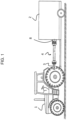
- Figure 1 shows a tractor 1 with a trailer-mounted implement 2.
- the implement 2 is connected by means of a universal joint arrangement 4 from the power take-off shaft 3 of the Tractor 1 is driven.
- the universal joint shaft arrangement 4 is attached to the power take-off shaft 3 and connected thereto in a rotationally fixed manner.
- the universal joint shaft arrangement 4 is also connected to a drive element of a transmission 8 of the implement 2.
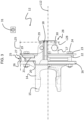
- FIG 2 shows the cardan shaft arrangement 4 in a schematic overview sketch.
- the cardan shaft arrangement 4 comprises a shaft fork 13 and a coupling fork 14, which are connected to one another in a known manner via a cross assembly 15.
- the shaft fork 13 and the coupling fork 14 each have openings in fork sections in which the cross assembly 15 is inserted.
- the shaft fork 13 is connected in a rotationally fixed manner to a shaft 4' of the cardan shaft arrangement 4.
- the coupling fork 14 is detachably connected in terms of drive to an input shaft 10 of the transmission 8 via a coupling 12.
- the coupling 12 is arranged so as to be rotatable about a rotation axis L12.
- the clutch 12 has a first clutch element and a second clutch element which are coupled to one another in such a way that when a maximum torque is exceeded, a relative rotational movement of the two clutch elements to one another can take place.
- the first clutch element is designed as a clutch flange 16, into which the clutch fork 14 is integrated.
- the second clutch element is designed as an output element 17.
- the output element 17 comprises an internal spline 18, into which a complementary external spline 11 of the input shaft 10 of the transmission 8 is inserted.
- the output element 17 and the input shaft 10 of the transmission 8 are thus connected to one another in a rotationally fixed manner.
- the output element 17 has a friction flange 19, which is at least indirectly frictionally connected to the clutch flange 16.
- the clutch 12 also comprises a first friction plate 20, a second friction plate 21, a pressure ring 22 and a spring ring 23.
- the first friction plate 20 is between the clutch flange 16 and the Friction flange 19 of the output element 17 is arranged or clamped.
- the first friction plate 20 is thus in contact with the friction flange 19 on a first axial side thereof. It is also conceivable that the first friction plate 20 is firmly connected to the clutch flange 16.
- the second friction plate 21 On a second axial side of the friction flange 19, the second friction plate 21 is in contact with the friction flange 19. The friction flange 19 is thus clamped between the first friction plate 20 and the second friction plate 21 and is held by them in a frictionally engaged manner in the circumferential direction.
- the second friction plate 21 is arranged between the friction flange 19 and the pressure ring 22 or clamped between them. It is also conceivable that the second friction plate 21 is firmly connected to the pressure ring 22.
- the pressure ring 22 is arranged or clamped between the second friction plate 21 and the spring ring 23. It is also conceivable that the pressure ring 22 is firmly connected to the spring ring 23.
- the spring ring 23 applies a compressive force in the axial direction to the pressure ring 22, the second friction plate 21, the friction flange 19, the first friction plate 20, and the clutch flange 16, so that the elements mentioned are clamped together.
- one or more clamping devices 24 extend through an opening in the spring ring 23 and through an opening in the clutch flange 16.
- the clamping devices 24 are designed as a screw that is secured by a nut. By tightening the nut, the clamping force is introduced into the screw.
- the clamping devices 24 are arranged in such a way that a rotational movement of the friction flange 19 about the axis of rotation L12 can take place at least in a circumferential section without the friction flange 19 coming into contact with the clamping devices 24.
- the coupling 12 has a first magnet 25 as a magnetic field source 25, which in the present case is attached to the coupling flange 16.
- the first magnet 25 can be inserted into a recess in the coupling flange 16 or glued to the coupling flange 16.
- the first magnet 25 can be cast into the coupling flange 16.
- the first magnet 25 is integrated into the coupling flange 16.
- an outer peripheral section of the coupling flange 16 can be magnetized and the first Magnets.
- the first magnet 25 could in principle also be attached to or integrated into one of the elements first friction plate 20, second friction plate 21, pressure ring 22 and spring ring 23.
- the first magnet 25 comprises a north pole 26 and a south pole 27.
- the first magnet 25 is designed as a bar magnet, wherein the imaginary straight connection of the north pole 26 and the south pole 27 defines a longitudinal axis L25 of the first magnet 25.
- the longitudinal axis L25 is arranged parallel to the axis of rotation L12.
- the first magnet 25 represents a magnetic field source of a sensor arrangement which is designed to determine the slip or a relative rotational speed between the coupling flange 16 and the output element 17.
- the magnetic field source or the first magnet 25 generates an output magnetic field of the sensor arrangement.
- the first coupling element or the coupling flange 16 has ferromagnetic properties at least in sections, so that the field lines of the output magnetic field of the magnetic field source are influenced or guided by the coupling flange 16.
- the ferromagnetic sections of the coupling flange 16 thus represent a first magnetic field influencing element of the sensor arrangement.
- a second magnet 28 is attached to the output element 17 as a second magnet influencing element 28.
- the second magnet 28 is designed as a ring magnet that is arranged on an outer circumferential surface of the output element 17.
- the second magnet 28 is, for example, glued or screwed to the output element 17.
- the second magnet 28 can be cast into the output element 17.
- the second magnet 28 is integrated into the output element 17.
- an outer circumferential section of the output element 17 can be magnetized and form the second magnet.
- the second magnet 28 comprises a north pole 29 and a south pole 30, wherein the imaginary straight connection of the north pole 29 and the south pole 30 forms a longitudinal axis L28 of the second magnet 28.
- the longitudinal axis L28 is arranged in a radial plane with respect to the rotation axis L12.
- the clutch 12 is shown in a starting position in which the clutch flange 16 and the output element 17 are arranged in a respective mounting position without being rotated relative to one another in order to explain the functioning of the sensor arrangement by way of example. It is understood that the function of the sensor arrangement is not restricted to this starting position. In the starting position, the longitudinal axis L25 of the first magnet 25 and the longitudinal axis L28 of the second magnet 28 intersect at an intersection point.
- the south pole 27 of the first magnet 25 and the north pole 29 of the second magnet 28 face the intersection point in the starting position.
- opposite poles of the first magnet 25 and the second magnet 28 face the intersection point.
- the same poles of the first magnet 25 and the second magnet 28 can face the intersection point.
- the magnetic field of the second magnet 28 changes the course of the field lines of the output magnetic field of the magnetic field source or of the first magnet 25.
- the second magnet 28 thus represents a second magnetic field influencing element of the sensor arrangement.
- the first magnet 25, the coupling flange 16 as the first magnetic field influencing element and the second magnet 28 as the second magnetic field influencing element are arranged relative to one another in such a way that the initial magnetic field is converted into a superimposed magnetic field.
- a magnetic field sensor 31 which is designed to measure a parameter characterizing the superimposed magnetic field.
- the parameter can be, for example, the magnetic flux, the magnetic density or the orientation of the superimposed magnetic field at the measuring point of the magnetic field sensor 31.
- the cardan shaft arrangement 4 comprises a protective device 5, which has a protective funnel 6 and a protective pot 7.
- the protective funnel 6 surrounds the cardan joint with the shaft fork 13, the coupling fork 14 and the Cross assembly 15 at least in sections and is arranged within the protective pot 7.
- the protective pot 7 is firmly connected to a housing 9 of the gear 8 and extends along the axis of rotation L12, so that the protective pot 7 and the coupling 12 are arranged in axial overlap with one another.
- the magnetic field sensor 31 is attached to a stationary component which, in particular, does not rotate with the coupling 12 about the rotation axis L12. As can be seen from Figure 2 As can be seen, the magnetic field sensor 31 is specifically attached to the protective pot 7 on the transmission side. However, it is also conceivable that the magnetic field sensor 31 is attached to any desired location on the protective pot 7. For example, the magnetic field sensor 31 can be attached to the protective pot 7 in such a way that the magnetic field sensor 31 is arranged at least in sections in a radial plane with the first magnet 25 and/or in a radial plane with the second magnet 28. Alternatively, the magnetic field sensor 31 can also be attached directly to the housing 9 of the transmission 8.
- the magnetic field sensor 31 is designed to measure the orientation of the superimposed magnetic field in the measuring point of the magnetic field sensor 31. To do this, the magnetic field sensor 31 detects at least one coordinate of a vector of the magnetic field strength or a vector of the magnetic flux density of the superimposed magnetic field in an orthogonal coordinate system.
- the coordinate system is defined by the axis of rotation L12 and the shortest connection of the measuring point to the axis of rotation L12.
- the magnetic field sensor 31 detects a coordinate that is directed in the radial direction with respect to the axis of rotation L12. It is understood that, alternatively, a magnetic field sensor 31 that measures two or three coordinates of the vector can also be used.
- the latter is connected to an evaluation unit 33.
- the connection between the magnetic field sensor 31 and the evaluation unit 33 is wired.
- the connection is wireless.
- the evaluation unit 33 is designed from which the superposition magnetic field to determine a condition of the clutch using a characteristic variable.
- the evaluation unit 33 is further designed to generate a signal that characterizes the condition of the clutch depending on the condition determined.
- the evaluation unit 33 is also connectable or connected to a control unit of the tractor 1. The control unit of the tractor 1 can thus control the power supplied to the universal joint arrangement 4 via the power take-off shaft 3 depending on the signal transmitted by the evaluation unit 33.
- the friction flange 19 slips between the first friction plate 20 and the second friction plate 21 in the circumferential direction.
- the first magnet 25 and the second magnet 28 are thus displaced or rotated relative to one another in the circumferential direction.
- the longitudinal axis L25 of the first magnet 25 and the longitudinal axis L28 of the second magnet 28 are subsequently arranged out of phase with one another.
- the ferromagnetic sections of the clutch flange 16 or the first magnetic field influencing element have rotated about the longitudinal axis L12 relative to the second magnet 28 or the second magnetic field influencing element. This changes the orientation and local intensity of the superimposed magnetic field.
- This change can be detected at the measuring point by the magnetic field sensor 31 and thus a relative speed or a slip between the first clutch element 16 and the second clutch element 17 can be detected.
- the superimposed magnetic field rotates with the clutch 12 about the axis of rotation L12.
- the magnetic field sensor 31 thus passes through the superimposed magnetic field once per revolution.
- the magnetic field sensor and/or the evaluation unit 33 can detect the change in the superimposed magnetic field per revolution.
- the first magnet 25, the clutch flange 16, the second magnet 28 and the magnetic field sensor 31 are thus part of a sensor arrangement for detecting slip of the clutch 12.
- the sensor arrangement comprises exactly one magnetic field sensor. This is sufficient to determine the slip of the clutch.
- the sensor arrangement has several magnetic field sensors, each of which is designed to measure a parameter characterizing the superimposed magnetic field. The sensor arrangement can thus be redundantly protected. or the resolution of the sensor arrangement can be increased.
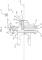
- the Figure 4 shows a clutch 12' in a second embodiment.
- the second embodiment of the clutch 12' differs from the first embodiment 12 only in the arrangement of the sensor arrangement, the structure of the rest of the clutch being identical.
- identical or similar parts are identified with the same reference numerals and reference is made to the description in the context of the first embodiment.
- the sensor arrangement of the second embodiment also comprises the first magnet 25 and the magnetic field sensor 31, with a modified second magnet 28' being provided.
- the second magnet 28' is designed as a bar magnet instead of a ring magnet and is firmly connected to the output element 17 of the clutch 12'. The second magnet 28' thus also rotates with the clutch 12' around the axis of rotation L12.
- the second magnet 28' comprises a north pole 29' and a south pole 30', wherein the imaginary straight connection of the north pole 29' and the south pole 30' defines a longitudinal axis L28 ⁇ of the second magnet 28.
- the longitudinal axis L28 ⁇ is arranged parallel to the axis of rotation L12 and to the longitudinal axis L25 of the first magnet 25.
- the coupling 12' is shown in a starting position in which the coupling flange 16 and the output element 17 are arranged in a respective mounting position without being rotated relative to one another in order to explain the functioning of the sensor arrangement by way of example. It is understood that the function of the sensor arrangement is not limited to this starting position.
- the longitudinal axis L25 of the first magnet 25, the longitudinal axis L28' of the second magnet 28' and the axis of rotation L12 are arranged in a common plane in the starting position.
- the friction flange 19 slips between the first friction plate 20 and the second friction plate 21 in the circumferential direction.
- the first magnet 25 and the second magnet 28 are thus displaced or spaced relative to one another in the circumferential direction.
- the longitudinal axis L25 of the first magnet 25, the longitudinal axis L28' of the second magnet 28' and the axis of rotation L12 are subsequently no longer arranged in a common plane.
- the ferromagnetic sections of the coupling flange 16 or the first magnetic field influencing element have rotated about the longitudinal axis L12 relative to the second magnet 28' or the second magnetic field influencing element. This changes the orientation and local intensity of the superimposed magnetic field. This change can be detected at the measuring point by the magnetic field sensor 31.
- the Figure 5 shows a clutch 12" in a third embodiment.
- the third embodiment of the clutch 12" differs from the first embodiment 12 only in the arrangement of the sensor arrangement, the structure of the rest of the clutch being identical.
- identical or similar parts are identified with the same reference numerals and reference is made to the description in the context of the first embodiment.
- the sensor arrangement of the third embodiment also comprises the second magnet 28 and the magnetic field sensor 31, wherein a modified first magnet 25" is provided.
- the first magnet 25" is designed as a bar magnet and is firmly connected to the coupling flange 16 of the coupling 12".
- the first magnet 25" comprises a north pole 26" and a south pole 27", wherein the imaginary straight connection of the north pole 26" and the south pole 27" defines a longitudinal axis L25" of the first magnet 25".
- the longitudinal axis L25" is arranged perpendicular to the axis of rotation L12 and parallel to the longitudinal axis L28 of the second magnet 28.
- the coupling 12" is shown in a starting position in which the coupling flange 16 and the output element 17 are arranged in a respective mounting position without being rotated relative to one another in order to explain the functioning of the sensor arrangement by way of example. It is understood that the function of the sensor arrangement is not limited to this starting position.
- the longitudinal axis L25" of the first magnet 25 and the longitudinal axis L28 of the second magnet 28 are arranged in a common plane with the axis of rotation L12 and in parallel radial planes which are axially spaced from each other.
- the friction flange 19 slips between the first friction plate 20 and the second friction plate 21 in the circumferential direction.
- the first magnet 25" and the second magnet 28 are thus displaced or rotated relative to one another in the circumferential direction.
- the longitudinal axis L25" of the first magnet 25", the longitudinal axis L28 of the second magnet 28 and the axis of rotation L12 are subsequently no longer arranged in a common plane.
- the ferromagnetic sections of the clutch flange 16 or the first magnetic field influencing element have rotated about the longitudinal axis L12 relative to the second magnet 28 or the second magnetic field influencing element. This changes the orientation and local intensity of the superimposed magnetic field. This change can be detected at the measuring point by the magnetic field sensor 31.
- FIG. 6 shows a clutch 12′′′ in a fourth embodiment.
- the fourth embodiment of the clutch 12′′′ differs from the first embodiment 12 only in the arrangement of the sensor arrangement, the structure of the rest of the clutch being identical.
- identical or similar parts are identified with the same reference numerals and reference is made to the description in the context of the first embodiment.
- the sensor arrangement of the fourth embodiment also comprises the first magnet 25 and the magnetic field sensor 31, whereby the second magnet 28 as a second magnetic field influencing element is dispensed with.
- the output element 17 comprises a ferromagnetic section as a second magnetic field influencing element 34.
- the ferromagnetic section can have an increased magnetic permeability compared to the rest of the output element 17.
- the ferromagnetic section can either be integrated into the output element 17 or connected to it.
- the ferromagnetic section as a second magnetic field influencing element 34 runs thus also with the coupling 12′′′ around the axis of rotation L12.
- the coupling 12′′′ is shown in a starting position in which the coupling flange 16 and the output element 17 are arranged in a respective mounting position without rotation relative to one another in order to explain the functioning of the sensor arrangement by way of example. It is understood that the function of the sensor arrangement is not limited to this starting position.
- the longitudinal axis L25 of the first magnet 25, the ferromagnetic section as the second magnetic field influencing element 34 and the axis of rotation L12 are arranged in a common longitudinal plane in the starting position.
- the friction flange 19 slips between the first friction plate 20 and the second friction plate 21 in the circumferential direction.
- the first magnet 25 and the ferromagnetic section as the second magnetic field influencing element 34 are thus displaced or spaced apart relative to one another in the circumferential direction.
- the longitudinal axis L25 of the first magnet 25, the ferromagnetic section and the axis of rotation L12 are subsequently no longer arranged in a common plane.
- the ferromagnetic sections of the clutch flange 16 or the first magnetic field influencing element have rotated about the longitudinal axis L12 relative to the ferromagnetic section or the second magnetic field influencing element. This changes the orientation and local intensity of the superimposed magnetic field. This change can be detected at the measuring point by the magnetic field sensor 31.
Landscapes
- Physics & Mathematics (AREA)
- General Physics & Mathematics (AREA)
- Engineering & Computer Science (AREA)
- General Engineering & Computer Science (AREA)
- Mechanical Engineering (AREA)
- Hydraulic Clutches, Magnetic Clutches, Fluid Clutches, And Fluid Joints (AREA)
Abstract
Sensoranordnung zur Schlupferkennung zwischen einem ersten Kupplungselement und einem zweiten Kupplungselement einer Kupplung, insbesondere einer Überlastkupplung, umfassend: eine Magnetfeldquelle (25), die ein erstes Ausgangsmagnetfeld erzeugt, ein erstes Magnetfeldbeeinflussungselement, das mit dem ersten Kupplungselement (16) verbindbar ist oder mit dem ersten Kupplungselement (16) integral ausgestaltet ist, ein zweites Magnetfeldbeeinflussungselement (28, 34), das mit dem zweiten Kupplungselement (17) verbindbar ist oder mit dem zweiten Kupplungselement (17) integral ausgestaltet ist, wobei die Magnetfeldquelle (25), das erste Magnetfeldbeeinflussungselement und das zweite Magnetfeldbeeinflussungselement (28, 34) so zueinander angeordnet sind, dass das Ausgangsmagnetfeld der Magnetfeldquelle von dem ersten Magnetfeldbeeinflussungselement und von dem zweiten Magnetfeldbeeinflussungselement (28, 34) in ein Überlagerungsmagnetfeld überführt wird, und einen Magnetfeldsensor (31), der ausgestaltet ist, eine das Überlagerungsmagnetfeld kennzeichnende Kenngröße zu messen. Eine Auswerteeinheit ermittelt aus der das Überlagerungsmagnetfeld kennzeichnenden Kenngröße den Schlupf der Kupplung und erzeugt in Abhängigkeit des Schlupfes ein Signal, das den Zustand der Kupplung charakterisiert.
Description
- Die vorliegende Erfindung betrifft eine Sensoranordnung zur Schlupferkennung an einer Kupplung mit einem ersten Kupplungselement und einem zweiten Kupplungselement, das mit dem ersten Kupplungselement koppelbar ist.
- Blockieren angetriebenen Arbeitsmaschinen schlagartig, können die resultierenden Drehmomente aufgrund der abzubremsenden rotierenden Massen die Nenndrehmomente der Arbeitsmaschine um ein Vielfaches übertreffen und so die Arbeitsmaschine schwerwiegend schädigen. Sicherheitskupplungen schützen diese Antriebsmaschinen vor derartigen Drehmomentschlägen. Die Kupplung trennt bei Erreichung eines Grenzmoments beide Seiten des Antriebsstrangs zumindest zeitweise voneinander. Dabei kann die Trennung dauerhaft erfolgen, beispielsweise bei Scherbolzenkupplungen, oder die relative Verdrehung zweier Teile der Kupplung zueinander kann zeitweise ermöglicht werden, wie beispielweise bei der in
DE 10 139 576 A1 gezeigten Überlast-Rutschkupplung. - Aus
DE 39 06 050 A1 ist ein Antriebstrang einer landwirtschaftlichen Maschine bekannt, mit einer Überlastrutschkupplung, die eine von einem Traktor angetriebene Gelenkwelle mit einer an den Traktor angehängten Arbeitsmaschine verbindet. Die Kupplung wird von einer Sensoranordnung zur Schlupferkennung überwacht, die einen ersten mit einem Eingangsteil der Kupplung verbundenen Drehzahlsensor und einen zweiten mit einem Ausgangsteil der Kupplung verbundenen Drehzahlsensor aufweist. Die Drehzahlsensoren umfassen jeweils eine auf das Eingangsteil respektive das Ausgangsteil aufgesetzte Zahnscheibe und einen induktiven Drehzahlmesser. Der Schlupf in der Kupplung kann durch die Detektion von Drehzahlunterschieden zwischen dem Eingangsteil und dem Ausgangsteil festgestellt werden. - Hiervon ausgehend liegt der vorliegenden Erfindung die Aufgabe zugrunde, eine Sensoranordnung zur Schlupferkennung einer Kupplung bereitzustellen, die platzsparend ist und eine bauraumoptimierte Anordnung in der Kupplung ermöglicht. Eine weitere Aufgabe der vorliegenden Erfindung ist die Bereitstellung einer Kupplung, insbesondere für eine Gelenkwelle, mit einer solchen Sensoranordnung sowie die Bereitstellung einer Gelenkwelle mit einer solchen Kupplung.
- Zur Lösung der Aufgabe wird eine Sensoranordnung zur Schlupferkennung an einer Kupplung mit einem ersten Kupplungselement und einem zweiten Kupplungselement, das mit dem ersten Kupplungselement koppelbar ist, vorgeschlagen, umfassend: eine Magnetfeldquelle, die ein erstes Ausgangsmagnetfeld erzeugt, ein erstes Magnetfeldbeeinflussungselement, das mit dem ersten Kupplungselement verbindbar ist oder mit dem ersten Kupplungselement integral ausgestaltet ist, ein zweites Magnetfeldbeeinflussungselement, das mit dem zweiten Kupplungselement verbindbar ist oder mit dem zweiten Kupplungselement integral ausgestaltet ist, wobei die Magnetfeldquelle, das erste Magnetfeldbeeinflussungselement und das zweite Magnetfeldbeeinflussungselement so zueinander angeordnet sind, dass das Ausgangsmagnetfeld der Magnetfeldquelle durch das erste Magnetfeldbeeinflussungselement und durch das zweite Magnetfeldbeeinflussungselement in ein Überlagerungsmagnetfeld überführt wird, und einen Magnetfeldsensor, der ausgestaltet ist, eine das Überlagerungsmagnetfeld kennzeichnende Kenngröße zu messen.
- Die Sensoranordnung kann insbesondere an einer Überlastkupplung einer Gelenkwelle verwendet werden.
- Ein Magnetfeldbeeinflussungselement kann beispielsweise ein separates Element sein, dass eine erhöhte magnetische Permeabilität oder eine verringerte magnetische Permeabilität gegenüber dem jeweiligen zugeordneten Kupplungselement aufweist. In einer anderen Ausgestaltung kann ein Magnetfeldbeeinflussungselement ein Abschnitt des jeweiligen Kupplungselements sein, dass eine erhöhte magnetische Permeabilität oder eine verringerte magnetische Permeabilität gegenüber einem anderen Abschnitt, insbesondere gegenüber dem Rest, des jeweiligen zugeordneten Kupplungselements aufweist. Der als Magnetfeldbeeinflussungselement ausgestaltete Abschnitt des jeweiligen Kupplungselements kann insbesondere bezüglich der Drehachse des Kupplungselements eine von rotationssymmetrisch abweichende Form aufweisen. Ein Magnetfeldbeeinflussungselement kann insbesondere ein ferromagnetischer Abschnitt des jeweiligen Kupplungselements sein. Ein Magnetfeldbeeinflussungselement kann zudem als Magnetfeldquelle, beispielsweise als Magnetelement oder als magnetisierter Abschnitt des jeweiligen Kupplungselements, ausgeführt sein.
- In einer möglichen Ausführungsform kann der Magnetfeldsensor dazu ausgestaltet sein, an einem Messpunkt die das Überlagerungsmagnetfeld kennzeichnende Kenngröße zu messen. Der Messpunkt kann dabei durch die räumliche Anordnung und den Aufbau des Magnetfeldsensors definiert sein. Es versteht sich, dass der Messpunkt nicht einschränkend als nichtausgedehnter oder infinitesimaler Ort in einem Raum zu verstehen ist, sondern auch durch eine Messfläche in dem Raum definiert sein kann. Die Sensoranordnung kann genau einen Magnetfeldsensor aufweisen. Es ist aber auch denkbar, dass mehrere Magnetfeldsensoren jeweils eine das Überlagerungsmagnetfeld kennzeichnende Kenngröße messen.
- Insbesondere kann der Magnetfeldsensor dazu ausgestaltet sein, an dem Messpunkt den Betrag der magnetischen Feldstärke oder den Betrag der magnetischen Flussdichte als kennzeichnende Kenngröße zu messen. Alternativ oder in Kombination kann der Magnetfeldsensor dazu ausgestaltet sein, an dem Messpunkt die Ausrichtung des Überlagerungsmagnetfeldes als kennzeichnende Größe zu messen. Der Magnetfeldsensor kann insbesondere dazu ausgestaltet sein, zumindest eine Koordinate eines Vektors der magnetischen Feldstärke oder eines Vektors der magnetischen Flussdichte zu messen. Es versteht sich somit das der Magnetfeldsensor ausgestaltet sein kann, eine, zwei oder drei Koordinaten des Vektors der magnetischen Feldstärke oder des Vektors der magnetischen Flussdichte zu messen, wobei die Koordinatenachsen insbesondere Achsen eines orthogonalen Koordinatensystems sind. Die kennzeichnende Kenngröße des Überlagerungsmagnetfelds kann somit beispielweise die magnetische Feldstärke, die magnetische Flussdichte oder die Ausrichtung des Überlagerungsmagnetfeldes sein. Der Magnetfeldsensor kann dazu ausgestaltet sein, die Änderung der kennzeichnenden Kenngröße über der Zeit zu ermitteln.
- In einer möglichen Ausführungsform kann eine Auswerteeinheit vorgesehen sein, die ausgestaltet ist, aus der das Überlagerungsmagnetfeld kennzeichnenden Kenngröße den Schlupf der Kupplung zu ermitteln. Der Schlupf der Kupplung wird dabei durch die relative Drehzahldifferenz zwischen dem ersten Kupplungselement und dem zweiten Kupplungselement definiert.
- Die Auswerteeinheit kann dazu ausgestaltet sein, in Abhängigkeit des ermittelten Schlupfes ein Signal zu erzeugen, das den Zustand der Kupplung charakterisiert. Der Zustand der Kupplung kann insbesondere durch einen oder mehrere Werte von der Relativdrehzahl zwischen dem ersten Kupplungselement und dem zweiten Kupplungselement, dem Schlupf zwischen dem ersten Kupplungselement und dem zweiten Kupplungselement, der Temperatur der Kupplung oder einzelner Kupplungselemente sowie dem Verschließ einzelner Kupplungselement beschrieben sein.
- Die Auswerteeinheit kann mit einer externen Steuereinheit verbindbar sein. Die externe Steuereinheit kann beispielsweise die Steuereinheit einer Antriebsanordnung oder einer Abtriebsanordnung sein.
- In einer möglichen Ausführungsform kann der Magnetfeldsensor zumindest zeitweise innerhalb des Überlagerungsmagnetfeldes angeordnet sein. Dies kann beispielsweise dann der Fall sein, wenn die Magnetfeldquelle relativ zu dem Magnetfeldsensor drehbar angeordnet ist. Das Überlagerungsmagnetfeld läuft in diesem Fall um eine Drehachse um und der Magnetfeldsensor durchläuft das Überlagerungsmagnetfeldes bei jeder Umdrehung.
- In einer möglichen Ausführungsform kann der Magnetfeldsensor mit einem zu der Drehachse respektive der Kupplung ortsfesten Element befestigbar sein. Dies weist den Vorteil auf, dass eine einfache kabelgebunden Verbindung zu der Auswerteeinheit hergestellt werden kann. Alternativ ist es denkbar, dass der Magnetfeldsensor mit einem von dem ersten Kupplungselement und dem zweiten Kupplungselement verbindbar ist, wobei der Magnetfeldsensor im Grundzustand der Kupplung dauerhaft in dem Überlagerungsmagnetfeldes angeordnet ist. Der Grundzustand der Kupplung ist dabei der Zustand, in der das erste Kupplungselement und das zweite Kupplungselement bezüglich einer Ausgangsstellung nicht relativ zueinander verdreht sind. In dieser Ausgestaltung ist der Magnetfeldsensor drehend angeordnet und das Signal des Magnetfeldsensors muss dementsprechend von dem drehend Teil abgenommen werden. Dies ist beispielsweise durch einen Schleifkontakt oder eine Funkverbindung möglich.
- In einer möglichen Ausführungsform kann die Magnetfeldquelle mit einem von dem ersten Kupplungselement und dem zweiten Kupplungselement verbindbar sein. Die Magnetfeldquelle kann insbesondere als separates Magnetelement ausgestaltet sein, beispielsweise als Ringmagnet oder als Stabmagnet. Alternativ kann die Magnetfeldquelle mit einem von dem ersten Kupplungselement und dem zweiten Kupplungselement integral ausgestaltet sein. Beispielsweise kann die Magnetfeldquelle ein magnetisierter Abschnitt des entsprechenden Kupplungselements sein.
- In einer weiteren möglichen Ausführungsform kann das erste Magnetfeldbeeinflussungselement und/oder das zweite Magnetfeldbeeinflussungselement als eine weitere Magnetfeldquelle ausgestaltet sein. Die weitere Magnetfeldquelle kann insbesondere ein separates Magnetelement sein. Alternativ kann die weitere Magnetfeldquelle mit einem von dem ersten Kupplungselement und dem zweiten Kupplungselement integral ausgestaltet sein. Beispielsweise kann die weitere Magnetfeldquelle ein magnetisierter Abschnitt des entsprechenden Kupplungselements sein.
- In einer möglichen Ausführungsform kann die Magnetfeldquelle und/oder die weitere Magnetfeldquelle ein Permanentmagnet oder ein Elektromagnet sein.
- Zur Lösung der der Erfindung zugrunde liegenden Aufgabe wird ferner eine Kupplung, insbesondere für eine Gelenkwelle, vorgeschlagen, umfassend: ein erstes Kupplungselement, ein zweites Kupplungselement, das mit dem ersten Kupplungselement koppelbar ist, eine Sensoranordnung in einer zuvor beschrieben Ausführung, wobei das erste Magnetfeldbeeinflussungselement mit dem ersten Kupplungselement verbunden oder mit dem ersten Kupplungselement integral ausgestaltet ist, und das zweite Magnetfeldbeeinflussungselement mit dem zweiten Kupplungselement verbunden oder mit dem zweiten Kupplungselement integral ausgestaltet ist.
- In einer möglichen Ausführungsform kann die Kupplung um eine Drehachse drehbar angeordnet sein. Das erste Kupplungselement und das zweite Kupplungselement können relativ zu dem Magnetfeldsensor um die Drehachse drehbar angeordnet sein.
- In einer möglichen Ausführungsform der Kupplung kann der Magnetfeldsensor an einem zu der Drehachse respektive der Kupplung ortsfesten Element befestigt oder befestigbar sein. Alternativ kann der Magnetfeldsensor mit einem von dem ersten Kupplungselement und dem zweiten Kupplungselement fest verbunden sein.
- In einer möglichen Ausführungsform der Kupplung kann der Magnetfeldsensor einen größeren Abstand von der Drehachse aufweisen als jeweils das erste Magnetfeldbeeinflussungselement und das zweite Magnetfeldbeeinflussungselement. Alternativ oder in Kombination kann der Magnetfeldsensor außerhalb einer zu der Drehachse koaxialen zylindrischen Einhüllenden jeweils des ersten Kupplungselements und des zweiten Kupplungselements angeordnet sein.
- In einer möglichen Ausführungsform der Kupplung kann die Magnetfeldquelle mit einem von dem ersten Kupplungselement und dem zweiten Kupplungselement verbunden oder integral ausgestaltet sein. Das erste Magnetfeldbeeinflussungselement und/oder das zweite Magnetfeldbeeinflussungselement kann als eine weitere Magnetfeldquelle ausgestaltet sein. Die weitere Magnetfeldquelle kann mit einem von dem ersten Kupplungselement und dem zweiten Kupplungselement verbunden oder integral ausgestaltet sein .
- In einer möglichen Ausführungsform kann die Kupplung ein Schutzelement umfassen, das zumindest abschnittsweise um das erste Kupplungselement und/oder das zweite Kupplungselement angeordnet ist, wobei der Magnetfeldsensor an dem Schutzelement befestigt ist. So kann der Magnetfeldsensor beispielsweise an dem Schutztopf einer Gelenkwelle befestigt sein.
- Zur Lösung der der Erfindung zugrunde liegenden Aufgabe wird des Weiteren eine Gelenkwellenanordnung vorgeschlagen, umfassend: ein drehbar angeordnetes Gelenkwellenelement, und eine Kupplung in einer zuvor beschriebenen Ausführungsform, wobei das Gelenkwellenelement mit dem ersten Kupplungselement verbunden ist.
- Nachfolgend werden mögliche Ausführungsformen der Erfindung anhand der Figurenzeichnungen erläutert. Hierin zeigt:
- Figur 1
- eine Ansicht eines Traktors, der über eine Gelenkwellenanordnung mit einem Arbeitsgerät verbunden ist,
- Figur 2
- eine schematische Schnittansicht durch die Gelenkwellenanordnung aus
Figur 1 im Bereich der Anbindung an das Arbeitsgerät, - Figur 3
- ein Schnittansicht der Kupplung aus
Figur 1 , - Figur 4
- ein Schnittansicht der Kupplung aus
Figur 1 in einer zweiten Ausführungsform, - Figur 5
- ein Schnittansicht der Kupplung aus
Figur 1 in einer dritten Ausführungsform, und - Figur 6
- ein Schnittansicht der Kupplung aus
Figur 1 in einer vierten Ausführungsform. -
Figur 1 zeigt einen Traktor 1 mit einem angehängten Arbeitsgerät 2. Das Arbeitsgerät 2 ist mittels einer Gelenkwellenanordnung 4 von der Zapfwelle 3 des Traktors 1 angetrieben. Hierzu ist die Gelenkwellenanordnung 4 auf die Zapfwelle 3 aufgesteckt und mit dieser drehfest verbunden. Geräteseitig ist die Gelenkwellenanordnung 4 ebenfalls mit einem Antriebselement eines Getriebes 8 des Arbeitsgeräts 2 antriebsverbunden. -
Figur 2 zeigt die Gelenkwellenanordnung 4, in einer schematischen Übersichtsskizze. Die Gelenkwellenanordnung 4 umfasst eine Wellengabel 13 und eine Kupplungsgabel 14, die über eine Kreuzgarnitur 15 in bekannter Weise kardanisch miteinander verbunden sind. Die Wellengabel 13 und die Kupplungsgabel 14 weisen jeweils Durchbrüche in Gabelabschnitten auf, in denen die Kreuzgarnitur 15 eingesetzt ist. Die Wellengabel 13 ist mit einer Welle 4' der Gelenkwellenanordnung 4 drehfest verbunden. Die Kupplungsgabel 14 ist über eine Kupplung 12 antriebsmäßig mit einer Eingangswelle 10 des Getriebes 8 lösbar verbunden. Die Kupplung 12 ist drehbar um eine Drehachse L12 angeordnet. - Wie aus der Zusammenschau der
Figuren 2 und3 erkennbar ist, weist die Kupplung 12 ein erstes Kupplungselement und ein zweites Kupplungselement auf, die so miteinander gekoppelt sind, dass beim Überschreiten eines maximalen Drehmoments eine relative Drehbewegung der beiden Kupplungselemente zueinander erfolgen kann. - Das erste Kupplungselement ist als Kupplungsflansch 16 ausgestaltet, in den die Kupplungsgabel 14 integriert ist. Das zweite Kupplungselement ist als Abtriebselement 17 ausgebildet. Das Abtriebselement 17 umfasst eine Innenkeilverzahnung 18, in die eine komplementäre Außenkeilverzahnung 11 der Eingangswelle 10 des Getriebes 8 eingesteckt ist. Das Abtriebselement 17 und die Eingangswelle 10 des Getriebes 8 sind somit drehfest miteinander verbunden.
- Das Abtriebselement 17 weist einen Reibflansch 19 auf, der zumindest mittelbar reibschlüssig mit dem Kupplungsflansch 16 verbunden ist. Hierzu umfasst die Kupplung 12 zudem eine erste Reiblamelle 20, eine zweite Reiblamelle 21, einen Druckring 22 und einen Federring 23.
- Die erste Reiblamelle 20 ist zwischen dem Kupplungsflansch 16 und dem Reibflansch 19 des Abtriebselements 17 angeordnet respektive eingespannt. Die erste Reiblamelle 20 ist somit auf einer ersten axialen Seite des Reibflansches 19 mit diesem in Anlage. Es ist auch denkbar, dass die erste Reiblamelle 20 mit dem Kupplungsflansch 16 fest verbunden ist.
- Auf einer zweiten axialen Seite des Reibflansches 19 ist die zweite Reiblamelle 21 mit dem Reibflansch 19 in Anlage. Der Reibflansch 19 ist somit zwischen der ersten Reiblamelle 20 und der zweiten Reiblamelle 21 eingespannt und wird reibschlüssig in Umfangsrichtung von diesen gehalten. Die zweite Reiblamelle 21 ist zwischen dem Reibflansch 19 und dem Druckring 22 angeordnet respektive zwischen diesen eingespannt. Es ist auch denkbar, dass die zweite Reiblamelle 21 mit dem Druckring 22 fest verbunden ist. Der Druckring 22 ist zwischen der zweiten Reiblamelle 21 und dem Federring 23 angeordnet respektive eingespannt. Es ist auch denkbar, dass der Druckring 22 mit dem Federring 23 fest verbunden ist.
- Der Federring 23 beaufschlagt in axialer Richtung den Druckring 22, die zweite Reiblamelle 21, den Reibflansch 19, die erste Reiblamelle 20, und den Kupplungsflansch 16 mit einer Druckkraft, sodass die genannten Elemente miteinander verspannt sind. Hierzu erstrecken sich ein oder mehrere Spannmittel 24 durch einen Durchbruch des Federrings 23 und durch einen Durchbruch in dem Kupplungsflansch 16. Im vorliegenden Fall sind die Spannmittel 24 als Schraube ausgeführt, die durch eine Mutter gesichert sind. Durch Festdrehen der Mutter wird die Verspannkraft in die Schraube eingeleitet. Die Spannmittel 24 sind dabei so angeordnet, dass eine Drehbewegung des Reibflansches 19 um die Drehachse L12 zumindest in einem Umfangsabschnitt erfolgen kann, ohne dass der Reibflansch 19 in Anlage mit den Spannmitteln 24 kommt.
- Die Kupplung 12 weist einen ersten Magneten 25 als Magnetfeldquelle 25 auf, der im vorliegenden Fall an dem Kupplungsflansch 16 befestigt ist. Der erste Magnet 25 kann dabei in eine Ausnehmung des Kupplungsflansches 16 eingesetzt sein oder mit dem Kupplungsflansch 16 verklebt sein. Alternativ kann der erste Magnet 25 in den Kupplungsflansch 16 eingegossen sein. Es ist auch denkbar, dass der erste Magnet 25 in den Kupplungsflansch 16 integriert ist. Beispielweise kann ein äußerer Umfangsabschnitt des Kupplungsflansches 16 magnetisiert sein und den ersten Magneten bilden. Der erste Magnet 25 könnte grundsätzlich aber auch an einem der Elemente erste Reiblamelle 20, zweite Reiblamelle 21, Druckring 22 und Federring 23 befestigt oder darin integriert sein.
- Der erste Magnet 25 umfasst einen Nordpol 26 und einen Südpol 27. Der erste Magnet 25 ist als Stabmagnet ausgeführt, wobei die gedachte gerade Verbindung des Nordpols 26 und des Südpols 27 eine Längsachse L25 des ersten Magneten 25 definiert. Die Längsachse L25 ist parallel zu der Drehachse L12 angeordnet.
- In der dargestellten Ausführungsform stellt der erste Magnet 25 eine Magnetfeldquelle einer Sensoranordnung dar, die dazu ausgestaltet ist, den Schlupf respektive eine Relativdrehzahl zwischen dem Kupplungsflansch 16 und dem Abtriebselement 17 zu ermitteln. Die Magnetfeldquelle respektive der erste Magnet 25 erzeugen ein Ausgangsmagnetfeld der Sensoranordnung.
- Das erste Kupplungselement respektive der Kupplungsflansch 16 weist zumindest abschnittsweise ferromagnetische Eigenschaften auf, sodass die Feldlinien des Ausgangsmagnetfeldes der Magnetfeldquelle durch den Kupplungsflansch 16 beeinflusst respektive geführt werden. Die ferromagnetischen Abschnitte des Kupplungsflansches 16 stellen somit ein erstes Magnetfeldbeeinflussungselement der Sensoranordnung dar.
- An dem Abtriebselement 17 ist ein zweiter Magnet 28 als zweites Magnetbeeinflussungselement 28 befestigt. Der zweite Magnet 28 ist als Ringmagnet ausgestaltet, der auf einer Außenumfangsfläche des Abtriebselements 17 angeordnet ist. Der zweite Magnet 28 ist beispielweise mit dem Abtriebselement 17 verklebt oder verschraubt. Alternativ kann der zweite Magnet 28 in das Abtriebselement 17 eingegossen sein. Es ist auch denkbar, dass der zweite Magnet 28 in das Abtriebselement 17 integriert ist. Beispielweise kann ein äußerer Umfangsabschnitt des Abtriebselements 17 magnetisiert sein und den zweiten Magneten bilden.
- Der zweite Magnet 28 umfasst einen Nordpol 29 und einen Südpol 30, wobei die gedachte gerade Verbindung des Nordpols 29 und des Südpols 30 eine Längsachse L28 des zweiten Magneten 28 definiert. Die Längsachse L28 ist in einer Radialebene bezüglich der Drehachse L12 angeordnet. In den
Figuren 2 und3 ist die Kupplung 12 in einer Ausgangsstellung dargestellt, in der der Kupplungsflansch 16 und das Abtriebselement 17 unverdreht zueinander in einer jeweiligen Montageposition angeordnet sind, um die Funktionsweise der Sensoranordnung beispielhaft zu erklären. Es versteht sich, dass die Funktion der Sensoranordnung nicht auf diese Ausgangsstellung beschränkt ist. In der Ausgangsstellung schneiden sich die Längsachse L25 des ersten Magneten 25 und die Längsachse L28 des zweiten Magneten 28 in einem Schnittpunkt. Der Südpol 27 des ersten Magneten 25 und der Nordpol 29 des zweiten Magneten 28 sind in der Ausgangsstellung dem Schnittpunkt zugewandt. Es sind somit gegengleiche Pole des ersten Magneten 25 und des zweiten Magneten 28 dem Schnittpunkt zugewandt. In einer anderen möglichen Ausgestaltung können jeweils die gleichen Pole des ersten Magneten 25 und des zweiten Magneten 28 dem Schnittpunkt zugewandt sein. - Das Magnetfeld des zweiten Magneten 28 verändert den Verlauf der Feldlinien des Ausgangsmagnetfeldes der Magnetfeldquelle respektive des ersten Magneten 25. Der zweite Magnet 28 stellt somit ein zweites Magnetfeldbeeinflussungselement der Sensoranordnung dar.
- Der erste Magnet 25, der Kupplungsflansch 16 als erstes Magnetfeldbeeinflussungselement und der zweite Magnet 28 als zweites Magnetfeldbeeinflussungselement sind so zueinander angeordnet, dass das Ausgangsmagnetfeld in ein Überlagerungsmagnetfeld überführt wird.
- Ferner ist in
Figur 2 die Positionierung eines Magentfeldsensors 31 dargestellt, der ausgestaltet ist, eine das Überlagerungsmagnetfeld kennzeichnende Kenngröße zu messen. Die Kenngröße kann beispielsweise der magnetische Fluss, die magnetische Dichte oder die Ausrichtung des Überlagerungsmagnetfeldes im Messpunkt des Magnetfeldsensors 31 sein. - Die Gelenkwellenanordnung 4 umfasst eine Schutzvorrichtung 5, die einen Schutztrichter 6 und einen Schutztopf 7 aufweist. Der Schutztrichter 6 umgibt das Kardangelenk mit der Wellengabel 13, der Kupplungsgabel 14 und der Kreuzgarnitur 15 zumindest abschnittsweise und ist innerhalb des Schutztopfes 7 angeordnet. Der Schutztopf 7 ist fest mit einem Gehäuse 9 des Getriebes 8 verbunden und erstreckt sich entlang der Drehachse L12, sodass der Schutztopf 7 und die Kupplung 12 in axialer Überdeckung zueinander angeordnet sind.
- Der Magnetfeldsensor 31 ist an einem ortsfesten Bauteil befestigt, das sich insbesondere nicht mit der Kupplung 12 um die Drehachse L12 dreht. Wie sich aus
Figur 2 erkennen lässt, ist der Magnetfeldsensor 31 konkret getriebeseitig an dem Schutztopf 7 befestigt. Es ist allerdings auch denkbar, dass der Magnetfeldsensor 31 an einer beliebigen Stelle des Schutztopfes 7 befestigt ist. Beispielweise kann der Magnetfeldsensor 31 so an dem Schutztopf 7 befestigt sein, dass der Magnetfeldsensor 31 zumindest abschnittsweise in einer Radialebene mit dem ersten Magneten 25 und/oder in einer Radialebene mit dem zweiten Magneten 28 angeordnet ist. Alternativ kann der Magnetfeldsensor 31 auch direkt an dem Gehäuse 9 des Getriebes 8 befestigt sein. - Im vorliegenden Fall ist der Magnetfeldsensor 31 dazu ausgestaltet, die Ausrichtung des Überlagerungsmagnetfeldes in dem Messpunkt des Magnetfeldsensor 31 zu messen. Hierzu erfasst der Magnetfeldsensor 31 zumindest eine Koordinate eines Vektors der magnetischen Feldstärke oder eines Vektors der magnetischen Flussdichte des Überlagerungsmagnetfeldes in einem orthogonalen Koordinatensystem. Das Koordinatensystem wird dabei durch die Drehachse L12 sowie die kürzeste Verbindung des Messpunktes mit der Drehachse L12 definiert. Im vorliegenden Fall wird durch den Magnetfeldsensor 31 eine Koordinate erfasst, die bezüglich der Drehachse L12 in die radiale Richtung gerichtet ist. Es versteht sich, dass alternativ auch ein Magnetfeldsensor 31 verwendet werden kann, der zwei oder drei Koordinaten des Vektors misst.
- Zu Auswertung des Signals des Magnetfeldsensors 31 ist dieser mit einer Auswerteeinheit 33 verbunden. Im vorliegenden Fall erfolgt die Verbindung zwischen Magnetfeldsensors 31 und Auswerteeinheit 33 kabelgebunden. Es ist aber auch denkbar, dass die Verbindung kabellos ausgestaltet ist.
- Die Auswerteeinheit 33 ist ausgestaltet, aus der das Überlagerungsmagnetfeld kennzeichnenden Kenngröße einen Zustand der Kupplung zu ermitteln. Die Auswerteeinheit 33 ist ferner dazu ausgestaltet, in Abhängigkeit des ermittelten Zustandes ein Signal zu erzeugen, das den Zustand der Kupplung charakterisiert. Die Auswerteeinheit 33 ist zudem mit einer Steuereinheit des Traktors 1 verbindbar bzw. verbunden. Somit kann die Steuereinheit des Traktors 1 die über die Zapfwelle 3 der Gelenkwellenanordnung 4 zugeführte Leistung in Abhängigkeit des von der Auswerteeinheit 33 übertragenen Signals steuern.
- Wird die Kupplung 12 mit einem Drehmoment beaufschlagt, das einen Schwellwert übersteigt, rutscht der Reibflansch 19 zwischen der ersten Reiblamelle 20 und der zweiten Reiblamelle 21 in Umfangsrichtung durch. Der erste Magnet 25 und der zweite Magnet 28 werden somit im Umfangsrichtung relativ zueinander verschoben respektive verdreht. Die Längsachse L25 des ersten Magneten 25 und die Längsachse L28 des zweiten Magneten 28 sind nachfolgend phasenversetzt zueinander angeordnet. Zudem haben sich die ferromagnetischen Abschnitte des Kupplungsflansches 16 respektive das erste Magnetfeldbeeinflussungselement zu dem zweiten Magneten 28 respektive zu dem zweiten Magnetfeldbeeinflussungselement um die Längsachse L12 verdreht. Hierdurch wird jeweils die Ausrichtung und lokale Intensität des Überlagerungsmagnetfeldes geändert. Diese Änderung kann in dem Messpunkt durch den Magnetfeldsensor 31 erfasst und so eine Relativdrehzahl oder ein Schlupf zwischen dem ersten Kupplungselement 16 und dem zweiten Kupplungselement 17 detektiert werden. Das Überlagerungsmagnetfeld rotiert mit der Kupplung 12 um die Drehachse L12. Somit durchläuft der Magnetfeldsensor 31 das Überlagerungsmagnetfeld je Umdrehung einmal. Der Magnetfeldsensor und/oder die Auswerteeinheit 33 können die Änderung des Überlagerungsmagnetfeldes je Umlauf erfassen.
- Der erste Magnet 25, der Kupplungsflansch 16, der zweite Magnet 28 und der Magnetfeldsensor 31 sind somit Teil einer Sensoranordnung zur Schlupferkennung der Kupplung 12. Die Sensoranordnung umfasst genau einen Magnetfeldsensor. Dies ist ausreichend, um den Schlupf der Kupplung zu ermitteln. Es ist allerdings auch denkbar, dass die Sensoranordnung mehrere Magnetfeldsensoren aufweist, die jeweils ausgestaltet sind, eine das Überlagerungsmagnetfeld kennzeichnende Kenngröße zu messen. Somit kann die Sensoranordnung redundant abgesichert werden oder die Auflösung der Sensoranordnung erhöht werden.
- Die
Figur 4 zeigt eine Kupplung 12' in einer zweiten Ausführungsform. Die zweite Ausführungsform der Kupplung 12' unterscheidet sich von der ersten Ausführungsform 12 nur durch die Anordnung der Sensoranordnung, wobei der Aufbau der restlichen Kupplung identisch ist. Insofern werden gleiche oder ähnliche Teile mit den gleichen Bezugszeichen gekennzeichnet und diesbezüglich auf die Beschreibung im Kontext der ersten Ausführungsform verwiesen. - Die Sensoranordnung der zweiten Ausführungsform umfasst ebenfalls den ersten Magneten 25 und den Magnetfeldsensor 31, wobei ein geänderter zweiter Magnet 28' vorgesehen ist. Der zweite Magnet 28' ist anstatt als Ringmagnet als Stabmagnet ausgestaltet und mit dem Abtriebselement 17 der Kupplung 12' fest verbunden. Der zweite Magnet 28' läuft somit auch mit der Kupplung 12' um die Drehachse L12 um.
- Der zweite Magnet 28' umfasst einen Nordpol 29' und einen Südpol 30', wobei die gedachte gerade Verbindung des Nordpols 29' und des Südpols 30' eine Längsachse L28` des zweiten Magneten 28 definiert. Die Längsachse L28` ist parallel zu der Drehachse L12 und zu der Längsachse L25 des ersten Magneten 25 angeordnet.
- In der
Figur 4 ist die Kupplung 12' in einer Ausgangsstellung dargestellt, in der der Kupplungsflansch 16 und das Abtriebselement 17 unverdreht zueinander in einer jeweiligen Montageposition angeordnet sind, um die Funktionsweise der Sensoranordnung beispielhaft zu erklären. Es versteht sich, dass die Funktion der Sensoranordnung nicht auf diese Ausgangsstellung beschränkt ist. Die Längsachse L25 des ersten Magneten 25, die Längsachse L28' des zweiten Magneten 28' und die Drehachse L12 sind in der Ausgangsstellung in einer gemeinsamen Ebene angeordnet. - Wird die Kupplung 12' mit einem Drehmoment beaufschlagt, das einen Schwellwert übersteigt, rutscht der Reibflansch 19 zwischen der ersten Reiblamelle 20 und der zweiten Reiblamelle 21 in Umfangsrichtung durch. Der erste Magnet 25 und der zweite Magnet 28 werden somit im Umfangsrichtung relativ zueinander verschoben respektive beabstandet. Die Längsachse L25 des ersten Magneten 25, die Längsachse L28' des zweiten Magneten 28' und die Drehachse L12 sind nachfolgend nicht mehr in einer gemeinsamen Ebene angeordnet. Zudem haben sich die ferromagnetischen Abschnitte des Kupplungsflansches 16 respektive das erste Magnetfeldbeeinflussungselement zu dem zweiten Magneten 28' respektive zu dem zweiten Magnetfeldbeeinflussungselement um die Längsachse L12 verdreht. Hierdurch wird jeweils die Ausrichtung und lokale Intensität des Überlagerungsmagnetfeldes geändert. Diese Änderung kann in dem Messpunkt durch den Magnetfeldsensor 31 erfasst werden.
- Die
Figur 5 zeigt eine Kupplung 12" in einer dritten Ausführungsform. Die dritte Ausführungsform der Kupplung 12" unterscheidet sich von der ersten Ausführungsform 12 nur durch die Anordnung der Sensoranordnung, wobei der Aufbau der restlichen Kupplung identisch ist. Insofern werden gleiche oder ähnliche Teile mit den gleichen Bezugszeichen gekennzeichnet und diesbezüglich auf die Beschreibung im Kontext der ersten Ausführungsform verwiesen. - Die Sensoranordnung der dritten Ausführungsform umfasst ebenfalls den zweiten Magneten 28 und den Magnetfeldsensor 31, wobei ein geänderter erster Magnet 25" vorgesehen ist. Der erste Magnet 25" ist als Stabmagnet ausgestaltet und mit dem Kupplungsflansch 16 der Kupplung 12" fest verbunden.
- Der erste Magnet 25" umfasst einen Nordpol 26" und einen Südpol 27", wobei die gedachte gerade Verbindung des Nordpols 26" und des Südpols 27" eine Längsachse L25" des ersten Magneten 25" definiert. Die Längsachse L25" ist senkrecht zu der Drehachse L12 und parallel zu der Längsachse L28 des zweiten Magneten 28 angeordnet.
- In der
Figur 5 ist die Kupplung 12" in einer Ausgangsstellung dargestellt, in der der Kupplungsflansch 16 und das Abtriebselement 17 unverdreht zueinander in einer jeweiligen Montageposition angeordnet sind, um die Funktionsweise der Sensoranordnung beispielhaft zu erklären. Es versteht sich, dass die Funktion der Sensoranordnung nicht auf diese Ausgangsstellung beschränkt ist. Die Längsachse L25" des ersten Magneten 25 und die Längsachse L28 des zweiten Magneten 28 sind in einer gemeinsamen Ebene mit der Drehachse L12 und in parallelen Radialebenen angeordnet, die axial voneinander beabstandet sind. - Wird die Kupplung 12" mit einem Drehmoment beaufschlagt, das einen Schwellwert übersteigt, rutscht der Reibflansch 19 zwischen der ersten Reiblamelle 20 und der zweiten Reiblamelle 21 in Umfangsrichtung durch. Der erste Magnet 25" und der zweite Magnet 28 werden somit im Umfangsrichtung relativ zueinander verschoben respektive verdreht. Die Längsachse L25" des ersten Magneten 25", die Längsachse L28 des zweiten Magneten 28 und die Drehachse L12 sind nachfolgend nicht mehr in einer gemeinsamen Ebene angeordnet. Zudem haben sich die ferromagnetischen Abschnitte des Kupplungsflansches 16 respektive das erste Magnetfeldbeeinflussungselement zu dem zweiten Magneten 28 respektive zu dem zweiten Magnetfeldbeeinflussungselement um die Längsachse L12 verdreht. Hierdurch wird jeweils die Ausrichtung und lokale Intensität des Überlagerungsmagnetfeldes geändert. Diese Änderung kann in dem Messpunkt durch den Magnetfeldsensor 31 erfasst werden.
-
Figur 6 zeigt eine Kupplung 12‴ in einer vierten Ausführungsform. Die vierte Ausführungsform der Kupplung 12‴ unterscheidet sich von der ersten Ausführungsform 12 nur durch die Anordnung der Sensoranordnung, wobei der Aufbau der restlichen Kupplung identisch ist. Insofern werden gleiche oder ähnliche Teile mit den gleichen Bezugszeichen gekennzeichnet und diesbezüglich auf die Beschreibung im Kontext der ersten Ausführungsform verwiesen. - Die Sensoranordnung der vierten Ausführungsform umfasst ebenfalls den ersten Magneten 25 und den Magnetfeldsensor 31, wobei auf den zweiten Magnet 28 als zweites Magnetfeldbeeinflussungselement verzichtet wird. Stattdessen umfasst das Abtriebselement 17 einen ferromagnetischen Abschnitt als zweites Magnetfeldbeeinflussungselement 34. Der ferromagnetische Abschnitt kann gegenüber der dem restlichen Abtriebselement 17 eine erhöhte magnetische Permeabilität aufweisen. Der ferromagnetische Abschnitt kann entweder in das Abtriebselement 17 integriert sein oder mit diesen verbunden sein. Der ferromagnetische Abschnitt als zweites Magnetfeldbeeinflussungselement 34 läuft somit auch mit der Kupplung 12‴ um die Drehachse L12 um.
- In
Figur 6 ist die Kupplung 12‴ in einer Ausgangsstellung dargestellt, in der der Kupplungsflansch 16 und das Abtriebselement 17 unverdreht zueinander in einer jeweiligen Montageposition angeordnet sind, um die Funktionsweise der Sensoranordnung beispielhaft zu erklären. Es versteht sich, dass die Funktion der Sensoranordnung nicht auf diese Ausgangsstellung beschränkt ist. Die Längsachse L25 des ersten Magneten 25, der ferromagnetische Abschnitt als zweites Magnetfeldbeeinflussungselement 34 und die Drehachse L12 sind in der Ausgangsstellung in einer gemeinsamen Längsebene angeordnet. - Wird die Kupplung 12‴ mit einem Drehmoment beaufschlagt, das einen Schwellwert übersteigt, rutscht der Reibflansch 19 zwischen der ersten Reiblamelle 20 und der zweiten Reiblamelle 21 in Umfangsrichtung durch. Der erste Magnet 25 und der ferromagnetische Abschnitt als zweites Magnetfeldbeeinflussungselement 34 werden somit im Umfangsrichtung relativ zueinander verschoben respektive beabstandet. Die Längsachse L25 des ersten Magneten 25, der ferromagnetische Abschnitt und die Drehachse L12 sind nachfolgend nicht mehr in einer gemeinsamen Ebene angeordnet. Zudem haben sich die ferromagnetischen Abschnitte des Kupplungsflansches 16 respektive das erste Magnetfeldbeeinflussungselement zu dem ferromagnetischen Abschnitt respektive zu dem zweiten Magnetfeldbeeinflussungselement um die Längsachse L12 verdreht. Hierdurch wird jeweils die Ausrichtung und lokale Intensität des Überlagerungsmagnetfeldes geändert. Diese Änderung kann in dem Messpunkt durch den Magnetfeldsensor 31 erfasst werden.
-
- 1
- Traktor
- 2
- Arbeitsgerät
- 3
- Zapfwelle
- 4
- Gelenkwelle
- 5
- Schutzvorrichtung
- 6
- Schutztrichter
- 7
- Schutztopf
- 8
- Getriebe
- 9
- Ortsfestes Element, Gehäuse des Getriebes
- 10
- Eingangswelle
- 11
- Außenkeilverzahnung
- 12
- Kupplung
- 13
- Wellengabel
- 14
- Kupplungsgabel
- 15
- Kreuzgarnitur
- 16
- Kupplungsflansch
- 17
- Abtriebselement
- 18
- Innenkeilverzahnung
- 19
- Reibflansch
- 20
- Reiblamelle
- 21
- Reiblamelle
- 22
- Druckring
- 23
- Federring
- 24
- Spannmittel
- 25
- Magnetfeldquelle, erster Magnet
- 26
- Nordpol
- 27
- Südpol
- 28
- Zweiter Magnet
- 29
- Nordpol
- 30
- Südpol
- 31
- Magnetfeldsensor
- 33
- Auswerteeinheit
- 34
- Zweites Magnetfeldbeeinflussungselement
- L
- Achse
Claims (15)
- Sensoranordnung zur Schlupferkennung zwischen einem ersten Kupplungselement und einem zweiten Kupplungselement einer Kupplung, insbesondere einer Überlastkupplung, umfassend:eine Magnetfeldquelle (25), die ein erstes Ausgangsmagnetfeld erzeugt,ein erstes Magnetfeldbeeinflussungselement, das mit dem ersten Kupplungselement (16) verbindbar ist oder mit dem ersten Kupplungselement (16) integral ausgestaltet ist,ein zweites Magnetfeldbeeinflussungselement (28, 34), das mit dem zweiten Kupplungselement (17) verbindbar ist oder mit dem zweiten Kupplungselement (17) integral ausgestaltet ist,wobei die Magnetfeldquelle (25), das erste Magnetfeldbeeinflussungselement und das zweite Magnetfeldbeeinflussungselement (28, 34) so zueinander angeordnet sind, dass das Ausgangsmagnetfeld der Magnetfeldquelle von dem ersten Magnetfeldbeeinflussungselement und von dem zweiten Magnetfeldbeeinflussungselement (28, 34) in ein Überlagerungsmagnetfeld überführt wird, undeinen Magnetfeldsensor (31), der ausgestaltet ist, eine das Überlagerungsmagnetfeld kennzeichnende Kenngröße zu messen.
- Sensoranordnung nach Anspruch 1,
dadurch gekennzeichnet,
dass der Magnetfeldsensor (31) dazu ausgestaltet ist, an einem Messpunkt die das Überlagerungsmagnetfeld kennzeichnende Kenngröße zu messen. - Sensoranordnung nach einem der Ansprüche 1 oder 2,
dadurch gekennzeichnet,
dass eine Auswerteeinheit (33) vorgesehen ist, die ausgestaltet ist, aus der das Überlagerungsmagnetfeld kennzeichnenden Kenngröße den Schlupf der Kupplung (12) zu ermitteln. - Sensoranordnung nach Anspruch 3,
dadurch gekennzeichnet,
dass die Auswerteeinheit (33) ausgestaltet ist, in Abhängigkeit des ermittelten Schlupfes ein Signal zu erzeugen, das den Zustand der Kupplung (12) charakterisiert. - Sensoranordnung nach einem der Ansprüche 3 oder 4,
dadurch gekennzeichnet,
dass die Auswerteeinheit (33) mit einer externen Steuereinheit verbindbar ist. - Sensoranordnung nach einem der Ansprüche 1 bis 5,
dadurch gekennzeichnet,
dass der Magnetfeldsensor (31) zumindest zeitweise innerhalb des Überlagerungsmagnetfeldes angeordnet ist. - Sensoranordnung nach einem der Ansprüche 1 bis 6,
dadurch gekennzeichnet,
dass die Magnetfeldquelle (25) mit einem von dem ersten Kupplungselement (16) und dem zweiten Kupplungselement (17) verbindbar ist,
wobei die Magnetfeldquelle (25) insbesondere als separates Magnetelement ausgestaltet ist. - Sensoranordnung nach Anspruch 7,
dadurch gekennzeichnet,
dass das erste Magnetfeldbeeinflussungselement und/oder das zweite Magnetfeldbeeinflussungselement (28, 34) als eine weitere Magnetfeldquelle ausgestaltet ist, wobei die weitere Magnetfeldquelle insbesondere ein separates Magnetelement ist. - Sensoranordnung nach Anspruch 8,
dadurch gekennzeichnet,
dass die Magnetfeldquelle (25) und/oder die weitere Magnetfeldquelle ein Permanentmagnet oder ein Elektromagnet ist. - Kupplung, insbesondere für eine Gelenkwelle, umfassend:ein erstes Kupplungselement (16),ein zweites Kupplungselement (17), das mit dem ersten Kupplungselement (16) koppelbar ist, undeine Sensoranordnung nach einem der Ansprüche 1 bis 9,wobei das erste Magnetfeldbeeinflussungselement mit dem ersten Kupplungselement (16) verbunden oder mit dem ersten Kupplungselement (16) integral ausgestaltet ist, unddas zweite Magnetfeldbeeinflussungselement (28, 34) mit dem zweiten Kupplungselement (17) verbunden oder mit dem zweiten Kupplungselement (17) integral ausgestaltet ist.
- Kupplung nach Anspruch 10,
dadurch gekennzeichnet,
dass die Kupplung (12) um eine Drehachse (L12) drehbar angeordnet ist, dass das erste Kupplungselement (16) und das zweite Kupplungselement (17) relativ zu dem Magnetfeldsensor (31) drehbar angeordnet sind, und/oder dass der Magnetfeldsensor (31) an einem ortsfesten Element (8, 9) befestigt ist, insbesondere an einem bezüglich der Drehachse (L12) ortsfesten Element (8, 9). - Kupplung nach Anspruch 11,
dadurch gekennzeichnet,dass der Magnetfeldsensor (31) einen größeren Abstand von der Drehachse (L12) aufweist als das erste Magnetfeldbeeinflussungselement und das zweite Magnetfeldbeeinflussungselement (28, 34),
und/oderdass der Magnetfeldsensor (31) außerhalb einer zu der Drehachse (L12) koaxialen zylindrischen Einhüllenden des ersten Kupplungselements (16) und des zweiten Kupplungselements (17) angeordnet ist. - Kupplung nach einem der Ansprüche 10 bis 12,
dadurch gekennzeichnet,dass die Magnetfeldquelle mit einem von dem ersten Kupplungselement (16) und dem zweiten Kupplungselement (17) verbunden oder integral ausgestaltet ist, unddass das erste Magnetfeldbeeinflussungselement und/oder das zweite Magnetfeldbeeinflussungselement als eine weitere Magnetfeldquelle ausgestaltet ist, die mit dem anderen von dem ersten Kupplungselement (16) und dem zweiten Kupplungselement (17) verbunden oder integral ausgestaltet ist. - Kupplung nach einem der Ansprüche 10 bis 13,
dadurch gekennzeichnet,dass die Kupplung (12) ein Schutzelement (7) umfasst, das zumindest abschnittsweise um das erste Kupplungselement (16) und das zweite Kupplungselement (17) angeordnet ist,wobei der Magnetfeldsensor (31) an dem Schutzelement (7) befestigt ist. - Gelenkwellenanordnung, umfassend:ein drehbar angeordnetes Gelenkwellenelement (13), undeine Kupplung (12) nach einem der Ansprüche 10 bis 14,wobei das Gelenkwellenelement (13) mit dem ersten Kupplungselement (16) verbunden ist.
Priority Applications (2)
| Application Number | Priority Date | Filing Date | Title |
|---|---|---|---|
| EP23191834.3A EP4509735A1 (de) | 2023-08-17 | 2023-08-17 | Sensoranordnung zur schlupferkennung an einer kupplung; eine kupplung mit einer solchen sensoranordnung und eine gelenkwelle mit einer solchen kupplung |
| US18/804,415 US20250060278A1 (en) | 2023-08-17 | 2024-08-14 | Sensor arrangement for slip detection on a clutch, a clutch with such a sensor arrangement and a universal joint shaft with such a clutch |
Applications Claiming Priority (1)
| Application Number | Priority Date | Filing Date | Title |
|---|---|---|---|
| EP23191834.3A EP4509735A1 (de) | 2023-08-17 | 2023-08-17 | Sensoranordnung zur schlupferkennung an einer kupplung; eine kupplung mit einer solchen sensoranordnung und eine gelenkwelle mit einer solchen kupplung |
Publications (1)
| Publication Number | Publication Date |
|---|---|
| EP4509735A1 true EP4509735A1 (de) | 2025-02-19 |
Family
ID=87760355
Family Applications (1)
| Application Number | Title | Priority Date | Filing Date |
|---|---|---|---|
| EP23191834.3A Withdrawn EP4509735A1 (de) | 2023-08-17 | 2023-08-17 | Sensoranordnung zur schlupferkennung an einer kupplung; eine kupplung mit einer solchen sensoranordnung und eine gelenkwelle mit einer solchen kupplung |
Country Status (2)
| Country | Link |
|---|---|
| US (1) | US20250060278A1 (de) |
| EP (1) | EP4509735A1 (de) |
Citations (6)
| Publication number | Priority date | Publication date | Assignee | Title |
|---|---|---|---|---|
| DE3906050A1 (de) | 1989-02-27 | 1990-08-30 | Walterscheid Gmbh Jean | Verfahren und einrichtung zum messen und anzeigen von belastungszustaenden in antriebsstraengen von landwirtschaftlichen geraeten |
| DE10139576A1 (de) | 2001-08-10 | 2003-03-06 | Renk Ag | Überlast-Rutschkupplung |
| EP2431714A1 (de) * | 2010-09-21 | 2012-03-21 | Zero-Max Holding DK A/S | Anordnung zur Messung der Verrutschung |
| DE102015111315A1 (de) * | 2015-07-13 | 2017-01-19 | Centa-Antriebe Kirschey Gmbh | Vorrichtung zur Übertragung von Drehmomenten und Verfahren |
| WO2021182354A1 (ja) * | 2020-03-10 | 2021-09-16 | 株式会社デンソー | 位置検出装置 |
| US20230228301A1 (en) * | 2020-02-17 | 2023-07-20 | Ratier-Figeac Sas | Torque limiter |
-
2023
- 2023-08-17 EP EP23191834.3A patent/EP4509735A1/de not_active Withdrawn
-
2024
- 2024-08-14 US US18/804,415 patent/US20250060278A1/en active Pending
Patent Citations (6)
| Publication number | Priority date | Publication date | Assignee | Title |
|---|---|---|---|---|
| DE3906050A1 (de) | 1989-02-27 | 1990-08-30 | Walterscheid Gmbh Jean | Verfahren und einrichtung zum messen und anzeigen von belastungszustaenden in antriebsstraengen von landwirtschaftlichen geraeten |
| DE10139576A1 (de) | 2001-08-10 | 2003-03-06 | Renk Ag | Überlast-Rutschkupplung |
| EP2431714A1 (de) * | 2010-09-21 | 2012-03-21 | Zero-Max Holding DK A/S | Anordnung zur Messung der Verrutschung |
| DE102015111315A1 (de) * | 2015-07-13 | 2017-01-19 | Centa-Antriebe Kirschey Gmbh | Vorrichtung zur Übertragung von Drehmomenten und Verfahren |
| US20230228301A1 (en) * | 2020-02-17 | 2023-07-20 | Ratier-Figeac Sas | Torque limiter |
| WO2021182354A1 (ja) * | 2020-03-10 | 2021-09-16 | 株式会社デンソー | 位置検出装置 |
Also Published As
| Publication number | Publication date |
|---|---|
| US20250060278A1 (en) | 2025-02-20 |
Similar Documents
| Publication | Publication Date | Title |
|---|---|---|
| DE102010006583B4 (de) | Drehmomentsensor mit Ausrichtungssystem | |
| WO2015181239A2 (de) | Magnetkupplung | |
| DE3545651A1 (de) | Kupplung mit einer nabe zum uebertragen eines drehmoments auf eine welle | |
| DE69211669T2 (de) | Antriebskraft-Übertragungsvorrichtung | |
| EP1424541B1 (de) | Vorrichtung zum Bestimmen eines auf eine Welle ausgeübten Drehmoments | |
| DE2233130C3 (de) | Sicherheitskupplung | |
| DE102016218017B3 (de) | Drehmomentenmessanordnung | |
| EP2984466A1 (de) | Sensorvorrichtung mit einer drehmomentsensoreinrichtung und einer inkrementalsensoreinrichtung und kraftfahrzeug | |
| EP2888493B1 (de) | Lagerring für ein lager, insbesondere für ein wälz- oder gleitlager | |
| EP2730686B1 (de) | Offenend-Spinnrotor | |
| EP2351198B1 (de) | Abgedichtete hysteresekupplung oder -bremse | |
| EP3325834B1 (de) | Anordnung zur drehverbindung einer belastungsmaschine eines prüfstandes mit einem prüfling | |
| DE3905251A1 (de) | Vorrichtung zum ermitteln des in einer welle uebertragenen drehmoments | |
| EP3313165B1 (de) | Antriebsstrang mit angetriebener welle, magnetostriktiver drehmomentmessung und integriertem freilauf | |
| EP1304495B1 (de) | Drehmomentbegrenzungskupplung | |
| DE19744042B4 (de) | Vorrichtung zum Bestimmen des Kupplungsverschleißzustandes | |
| EP1199550B1 (de) | Vorrichtung zum Messen von Drehmomenten in einer Antriebsanordnung | |
| EP3236566B1 (de) | Hysteresekupplung oder -bremse und drehmoment-justierverfahren | |
| DE102006054179A1 (de) | Vorrichtung zur Messung des Drehmomentes an einer Welle | |
| DE10160760B4 (de) | Antriebswelle mit Mitteln zur Drehmomentmessung | |
| DE3210167A1 (de) | Vorrichtung zur drehmomentbegrenzung | |
| DE102013214107B4 (de) | Getriebeanordnung | |
| DE2649252A1 (de) | Regelbares, elektromagnetisches kupplungs- und/oder bremssystem und verfahren zu seiner einstellung | |
| EP1310779A1 (de) | Vorrichtung zum Messen von Drehmomenten und der Drehrichtung in einer Antriebsanordnung | |
| DE102009014102A1 (de) | Sicherheitskupplung gegen Überlast, insbesondere für ein Walzgerüst oder eine Schere in einem Walzwerk |
Legal Events
| Date | Code | Title | Description |
|---|---|---|---|
| PUAI | Public reference made under article 153(3) epc to a published international application that has entered the european phase |
Free format text: ORIGINAL CODE: 0009012 |
|
| STAA | Information on the status of an ep patent application or granted ep patent |
Free format text: STATUS: THE APPLICATION HAS BEEN PUBLISHED |
|
| AK | Designated contracting states |
Kind code of ref document: A1 Designated state(s): AL AT BE BG CH CY CZ DE DK EE ES FI FR GB GR HR HU IE IS IT LI LT LU LV MC ME MK MT NL NO PL PT RO RS SE SI SK SM TR |
|
| STAA | Information on the status of an ep patent application or granted ep patent |
Free format text: STATUS: THE APPLICATION IS DEEMED TO BE WITHDRAWN |
|
| 18D | Application deemed to be withdrawn |
Effective date: 20250820 |