EP4509737A1 - Bremseinheit, motor-bremsen-kombination sowie verfahren zur luftspaltverstellung - Google Patents
Bremseinheit, motor-bremsen-kombination sowie verfahren zur luftspaltverstellung Download PDFInfo
- Publication number
- EP4509737A1 EP4509737A1 EP23192093.5A EP23192093A EP4509737A1 EP 4509737 A1 EP4509737 A1 EP 4509737A1 EP 23192093 A EP23192093 A EP 23192093A EP 4509737 A1 EP4509737 A1 EP 4509737A1
- Authority
- EP
- European Patent Office
- Prior art keywords
- brake
- longitudinal axis
- contact surfaces
- braking
- housing
- Prior art date
- Legal status (The legal status is an assumption and is not a legal conclusion. Google has not performed a legal analysis and makes no representation as to the accuracy of the status listed.)
- Granted
Links
Images






Classifications
-
- F—MECHANICAL ENGINEERING; LIGHTING; HEATING; WEAPONS; BLASTING
- F16—ENGINEERING ELEMENTS AND UNITS; GENERAL MEASURES FOR PRODUCING AND MAINTAINING EFFECTIVE FUNCTIONING OF MACHINES OR INSTALLATIONS; THERMAL INSULATION IN GENERAL
- F16D—COUPLINGS FOR TRANSMITTING ROTATION; CLUTCHES; BRAKES
- F16D55/00—Brakes with substantially-radial braking surfaces pressed together in axial direction, e.g. disc brakes
- F16D55/24—Brakes with substantially-radial braking surfaces pressed together in axial direction, e.g. disc brakes with a plurality of axially-movable discs, lamellae, or pads, pressed from one side towards an axially-located member
- F16D55/26—Brakes with substantially-radial braking surfaces pressed together in axial direction, e.g. disc brakes with a plurality of axially-movable discs, lamellae, or pads, pressed from one side towards an axially-located member without self-tightening action
- F16D55/28—Brakes with only one rotating disc
-
- F—MECHANICAL ENGINEERING; LIGHTING; HEATING; WEAPONS; BLASTING
- F16—ENGINEERING ELEMENTS AND UNITS; GENERAL MEASURES FOR PRODUCING AND MAINTAINING EFFECTIVE FUNCTIONING OF MACHINES OR INSTALLATIONS; THERMAL INSULATION IN GENERAL
- F16D—COUPLINGS FOR TRANSMITTING ROTATION; CLUTCHES; BRAKES
- F16D65/00—Parts or details
- F16D65/14—Actuating mechanisms for brakes; Means for initiating operation at a predetermined position
- F16D65/16—Actuating mechanisms for brakes; Means for initiating operation at a predetermined position arranged in or on the brake
- F16D65/18—Actuating mechanisms for brakes; Means for initiating operation at a predetermined position arranged in or on the brake adapted for drawing members together, e.g. for disc brakes
- F16D65/186—Actuating mechanisms for brakes; Means for initiating operation at a predetermined position arranged in or on the brake adapted for drawing members together, e.g. for disc brakes with full-face force-applying member, e.g. annular
-
- F—MECHANICAL ENGINEERING; LIGHTING; HEATING; WEAPONS; BLASTING
- F16—ENGINEERING ELEMENTS AND UNITS; GENERAL MEASURES FOR PRODUCING AND MAINTAINING EFFECTIVE FUNCTIONING OF MACHINES OR INSTALLATIONS; THERMAL INSULATION IN GENERAL
- F16D—COUPLINGS FOR TRANSMITTING ROTATION; CLUTCHES; BRAKES
- F16D55/00—Brakes with substantially-radial braking surfaces pressed together in axial direction, e.g. disc brakes
- F16D2055/0004—Parts or details of disc brakes
- F16D2055/0058—Fully lined, i.e. braking surface extending over the entire disc circumference
-
- F—MECHANICAL ENGINEERING; LIGHTING; HEATING; WEAPONS; BLASTING
- F16—ENGINEERING ELEMENTS AND UNITS; GENERAL MEASURES FOR PRODUCING AND MAINTAINING EFFECTIVE FUNCTIONING OF MACHINES OR INSTALLATIONS; THERMAL INSULATION IN GENERAL
- F16D—COUPLINGS FOR TRANSMITTING ROTATION; CLUTCHES; BRAKES
- F16D2121/00—Type of actuator operation force
- F16D2121/14—Mechanical
-
- F—MECHANICAL ENGINEERING; LIGHTING; HEATING; WEAPONS; BLASTING
- F16—ENGINEERING ELEMENTS AND UNITS; GENERAL MEASURES FOR PRODUCING AND MAINTAINING EFFECTIVE FUNCTIONING OF MACHINES OR INSTALLATIONS; THERMAL INSULATION IN GENERAL
- F16D—COUPLINGS FOR TRANSMITTING ROTATION; CLUTCHES; BRAKES
- F16D2121/00—Type of actuator operation force
- F16D2121/18—Electric or magnetic
- F16D2121/20—Electric or magnetic using electromagnets
- F16D2121/22—Electric or magnetic using electromagnets for releasing a normally applied brake
Definitions
- the invention relates to a brake unit, a motor-brake combination and a method for air gap adjustment.
- a brake usually has at least two brake elements that come into frictional contact with one another when the brake is closed. Often at least one of the brake elements has a friction lining for this purpose. When the brake is open, an air gap is arranged between the brake elements.
- this air gap There may be a need to adjust this air gap, or more precisely, the width of this air gap, for various reasons.
- a common reason is that as the brake is in use, the air gap increases due to wear on at least one of the brake elements, particularly the friction lining. As the air gap increases, the clearance also increases. If the width of the air gap exceeds a certain level, the function of the brake may be impaired. For example, spring-loaded brakes no longer function above a certain maximum gap width because the magnetic force of the electromagnet is then no longer sufficient to release the brake.
- the invention is therefore based on the object of providing a brake unit that enables simple, reliable and safe adjustment of the air gap and is also easy to manufacture.
- the invention is also based on the object of providing a corresponding motor-brake combination.
- the invention is based on the object of providing a simple, clear and safe method for adjusting the air gap.
- a brake unit comprises a unit longitudinal axis, a first brake element with a first element longitudinal axis, a second brake element with a second element longitudinal axis, and a housing.
- the second brake element also has a first end face, a braking surface and a plurality of different contact surfaces.
- a plurality of different contact surfaces is preferably understood to mean at least two different contact surfaces.
- the contact surfaces are arranged on the first end face of the second brake element, the second brake element can be firmly coupled to the housing by means of each of the contact surfaces, and the brake surface can be brought into operative connection with the first brake element when one of the contact surfaces is coupled to the housing, in particular to generate a braking effect.
- the different contact surfaces cannot be coupled to the housing at the same time.
- preferably only one of the different contact surfaces is coupled to the housing.
- a "fixed coupling” is understood here and below to mean a coupling that is designed in such a way that it does not allow any relative movement of the coupled parts to one another. However, the coupling is preferably designed to be detachable without causing any damage.
- the second brake element can be coupled to the housing in a particularly rotationally fixed manner. Additional elements, in particular spacers such as spacer sleeves, can be arranged between the second brake element and the housing coupled to it.
- the different contact surfaces differ in that they are at different distances from the braking surface along the second element longitudinal axis.
- the braking surface can preferably be arranged at different closeness to the first braking element.
- the width of the air gap preferably refers to an axial distance relative to the unit longitudinal axis.
- the distances are typically in the range from 0 to 1 mm.
- the smallest of the distances can be 0 mm and the largest of the distances can be in the range from 0.5 to 1 mm.
- the second braking element preferably has three different contact surfaces, namely a first contact surface, a second contact surface and a third contact surface.
- the first contact surface particularly preferably has the smallest and the third contact surface the largest of the distances.
- At least one friction lining is arranged on the first brake element, which is intended to come into frictional contact with the braking surface of the second brake element when the brake unit is closed.
- the wear-related removal of the at least one friction lining can be compensated for, at least in part.
- the braking surface is arranged on the first end face of the second brake element. This means that the bearing surfaces and the braking surfaces can be arranged on the same end face of the second brake element. This means that the assembly effort required to adjust the air gap can be reduced.
- dismantling the second brake element can be dispensed with, at least in part.
- the contact surfaces are arranged in a recess of the second brake element.
- the third contact surface along the unit longitudinal axis can thus be arranged, for example, deeper in the second brake element than the first contact surface.
- the contact surfaces are arranged parallel to the brake surface. This allows the adjustment of the distances the contact surface to the braking surface in production as well as the assembly of the second braking element can be simplified.
- the first brake element and the second brake element are preferably arranged one behind the other along the unit longitudinal axis in such a way that the first element longitudinal axis and the second element longitudinal axis are each arranged on and parallel to the unit longitudinal axis.
- the operative connection in particular in the form of a frictional contact, can thus be established by a displacement of the first brake element and/or the second brake element along the unit longitudinal axis.
- the second brake element can be essentially disc-shaped and can be arranged in such a way that the first end face is aligned perpendicular to the unit longitudinal axis.
- the second brake element is preferably designed as a rotating body and is particularly preferably arranged around the second element longitudinal axis.
- the second brake element can be designed as a housing cover when coupled to the housing. A second brake element that is essentially disc-shaped can be particularly suitable for this.
- an imaginary coupling circle is arranged on the first end face of the second braking element around the second longitudinal axis of the element, with the contact surfaces being arranged on the coupling circle.
- the contact surface to be coupled to the housing can be selected by rotating the second braking element relative to the housing around a coupling circle center point.
- the coupling circle center point is preferably arranged on the second longitudinal axis of the element.
- each of the contact surfaces is arranged on the coupling circle.
- the second braking element can have at least one contact section, each of which comprises one of the different contact surfaces.
- the at least one contact section comprises exactly one of the different contact surfaces.
- each of the at least one contact section preferably comprises three of the contact surfaces.
- the different contact surfaces of the at least one contact section can be arranged in ascending order according to their respective distance from the braking surface, preferably in the circumferential direction around the second element longitudinal axis. In this way, the air gap can be adjusted step by step by gradually rotating the second braking element relative to the housing.
- the different contact surfaces of the at least one contact section can be arranged at a distance from one another or directly adjacent to one another.
- a spaced arrangement is preferably understood to mean an arrangement that is spatially separated from one another. While a spaced arrangement makes it easy to clearly define the position of the housing with respect to the corresponding contact surface, the directly adjacent arrangement enables an air gap adjustment with comparatively little axial play.
- the contact surfaces of the at least one contact section are preferably arranged at an angle to one another with respect to the second longitudinal axis of the element and thus have an angular surface offset from one another.
- the surface offset is preferably in the range from 10° to 30°, particularly preferably in the range from 15° to 25°.
- the at least one contact section comprises a plurality of contact sections, preferably arranged at a distance from one another.
- the contact sections are preferably identical.
- the contact sections can be arranged at an angle to one another with respect to the second longitudinal axis of the element and thus have an angular section offset to one another.
- the section offset is preferably the offset of the corresponding contact surfaces of the various contact sections to one another.
- the section offset between the identical contact surfaces of different contact sections is greater than the surface offset between the contact surfaces of one of the contact sections.
- the contact sections are preferably arranged evenly offset from one another. In the case of three contact sections, this results in a section offset of 120°.
- the second brake element has at least one coupling hole for coupling the second brake element to the housing.
- the coupling hole can be designed as a threaded hole so that the second brake element can be fastened to the housing by means of at least one coupling screw.
- the coupling hole can be designed as a through hole for the coupling screw to pass through, with which the brake unit can be fastened to a motor flange, for example. In this case, the second brake element can be clamped between the housing and the motor flange and thus coupled to the housing.
- the at least one coupling hole can be arranged in at least one of the contact surfaces. This allows the application a bending moment on the second brake element by the at least one coupling screw can be avoided.
- the at least one coupling bore is arranged on the coupling circle.
- One of the at least one coupling bore can be arranged in each of the contact surfaces.
- the at least one coupling bore is designed as an elongated hole. This allows the air gap to be adjusted without having to remove the at least one coupling screw.
- the elongated hole preferably extends over all of the contact surfaces of the at least one contact section, particularly preferably along the coupling circle.
- the second brake element can therefore have exactly one of the at least one coupling bore in each of the at least one contact section.
- the first braking element is designed as a rotor and the second braking element as a stator.
- the first braking element is preferably arranged on a shaft to be braked.
- the first brake element can be arranged between the second brake element and a third brake element, preferably designed as a stator, wherein the third brake element is preferably axially displaceable along the unit longitudinal axis.
- the third brake element is preferably axially displaceable along the unit longitudinal axis.
- the surfaces provided for the frictional contact between the first brake element and the third brake element are preferably designed in accordance with the surfaces provided for the frictional contact between the first brake element and the second brake element.
- the second brake element is arranged so as to be axially displaceable along the unit's longitudinal axis. In order to close the brake unit, frictional contact can be established between the first brake element and the second brake element and between the first brake element and the third brake element.
- the brake unit is designed as a spring-loaded brake or permanent magnet brake.
- the second brake element can be designed as a brake flange and/or the third brake element as an armature.
- the brake flange here preferably refers to a component by means of which the brake unit can be arranged on another device, in particular one to be braked, such as a motor.
- the term armature here preferably refers to the component that can be directly influenced by an electromagnet for actuating the brake unit. The actuation of the brake unit can include both the opening and the closing of the brake unit.
- a motor-brake combination comprises a motor with a motor flange and a previously described brake unit, wherein the second brake element can be firmly coupled to the motor flange with a second end face facing the motor flange.
- the second end face is preferably arranged opposite the first end face.
- the second brake element preferably rests directly on the motor flange, particularly preferably with the second end face, at least in sections.
- the shaft can be formed by a motor shaft.
- the at least one coupling screw is preferably loosened. If the at least one coupling screw is arranged in the at least one coupling hole when the brake unit is assembled, the at least one coupling screw can then be removed.
- the second brake element can then be rotated about the unit's longitudinal axis relative to the housing, so that the housing can be coupled to the second brake element with a different contact surface than before. To do this, the second brake element is rotated, preferably by the surface offset or an integer multiple of the surface offset.
- the assembly can then take place in the corresponding reverse order. With this method for adjusting the air gap, the second brake element does not have to be dismantled any further, in particular not from the shaft. Such a procedure can therefore be particularly advantageous if the brake unit is inaccessible from the second brake element, for example because the motor can be arranged there, in particular in the case of the motor-brake combination.
- Fig. 1 to 4a show various views of a first embodiment of a brake unit 10 designed as a spring-loaded brake 11.
- the invention will first be explained using this embodiment as an example. As far as the second and third embodiments are concerned, the following will show how they differ from the first embodiment.
- the brake unit 10 comprises a unit longitudinal axis 12, a first brake element 14 designed as a rotor 13, a second brake element 16 designed as a stator 15 and a housing 20.
- the first brake element 14 is arranged on a shaft to be braked (not shown) that is arranged on the unit longitudinal axis 12.
- a first element longitudinal axis 22 of the first brake element 14 and a second element longitudinal axis 24 of the second brake element 16 are arranged one behind the other along the unit longitudinal axis 12 in such a way that the first element longitudinal axis 22 and the second element longitudinal axis 24 are each arranged on and parallel to the unit longitudinal axis 12.
- the second braking element 16 is designed as a disc-shaped body of rotation around the second longitudinal axis 24 of the element and also has a first end face 26 arranged perpendicular to the second longitudinal axis 24 of the element.
- the second braking element 16 also has a braking surface 28 and three contact sections 29, each with a plurality of different contact surfaces, namely a first contact surface 30, a second contact surface 32 and a third contact surface 34.
- the contact surfaces 30, 32, 34 are in particular in Fig. 1
- the contact surfaces 30, 32, 34 are arranged on the first end face 26, as is the braking surface 28.
- the contact surfaces 30, 32, 34 and the braking surfaces are arranged on the same front side of the second braking element 16.
- the second braking element 16 can be firmly coupled to the housing 20 by means of each of the contact surfaces 30, 32, 34.
- the second braking element 16 can thus be coupled to the housing 20 in a particularly rotationally fixed manner.
- the braking surface can be brought into operative connection with the first braking element 14 to generate a braking effect.
- the second brake element 16 has several coupling holes 36.
- the coupling holes 36 are designed as through holes for the passage of a coupling screw 38, with which the brake unit 10 can be attached, for example, to a not shown, in Fig. 2 can be attached to the motor flange to be arranged to the left of the brake unit 10.
- the second brake element 16 preferably rests against the motor flange with a second end face 37.
- the second end face 37 is arranged opposite the first end face 26.
- the second brake element 16 is in this case designed as a brake flange 39 and can be clamped between the housing 20 and the motor flange and thus coupled to the housing 20.
- the coupling can thus be designed to be detachable without causing any damage.
- additional components in the form of spacer sleeves 40 are arranged between the second brake element 16 and the housing 20.
- each of the coupling holes 36 is arranged in one of the contact surfaces 30, 32, 34. This allows the application of a bending moment to the second brake element 16 by tightening the coupling screws 38.
- the coupling holes 36 are arranged on an imaginary coupling circle 42, which is arranged on the first end face 26 of the second brake element 16.
- a coupling circle center 44 of the coupling circle 42 is arranged on the second element longitudinal axis 24.
- Fig. 2 further shows that the first brake element 14 is arranged between the second brake element 16 and a third brake element 46, which is also designed as a stator 15.
- the third brake element 46 is designed as an armature 48 of the spring-loaded brake 11 and is axially displaceable along the unit's longitudinal axis 12 to actuate the brake unit 10.
- a force can be exerted on the third brake element 46 by an electromagnet 50 arranged in the housing 20, which holds the brake unit 10 open against the force of compression springs 52 also arranged in the housing 20.
- the third brake element 46 By moving the third brake element 46 in the direction of the first brake element 14, a braking frictional contact can be formed between the first brake element 14 and the third brake element 46 and between the first brake element 14 and the second brake element 16.
- the second brake element 16 is also arranged to be axially displaceable along the unit longitudinal axis 12.
- the third brake element 46 also has a braking surface 53 for this purpose.
- each of the first contact surfaces 30 has a first distance
- each of the second contact surfaces 32 has a second distance 56
- each of the third contact surfaces 34 has a third distance 58 from the braking surface 28.
- the second distance 56 is shown in the Fig. 3 u. 3a and the third distance 58 in the Fig. 4 u. 4a.
- the first distance is shown in Fig. 8a u. 12a recognizable.
- Fig. 1 illustrates that the different contact surfaces 30, 32, 34 cannot be coupled to the housing 20 at the same time.
- the braking surface 28 of the second brake element 16 can be arranged at different close proximity to the first brake element 14. This makes it possible to adjust the width of an air gap which is arranged, in particular, between the first brake element 14 and the second brake element 16 when the brake unit 10 is open.
- the distances are typically in the range from 0 to 1 mm.
- the first distance can be 0 mm and the third distance 58 can be in the range from 0.5 to 1 mm.
- the second contact surface 32 and the third contact surface 34 are each arranged in a recess 60 of the second brake element 16.
- the third contact surface 34 is accordingly arranged deeper in the second brake element 16 than the second contact surface 32.
- the contact surfaces 30, 32, 34 are arranged parallel to the braking surface 28.
- Fig. 1 it can be seen that the contact surfaces 30, 32, 34 are arranged on the coupling circle 42.
- the contact surfaces 30, 32, 34 of each of the contact sections 29 are arranged in ascending order according to their respective distance from the braking surface 28 in the circumferential direction around the second element longitudinal axis 24.
- the air gap can thus be adjusted step by step by rotating the second braking element 16 relative to the housing 20.
- Each of the system sections 29 is identically designed.
- the system sections 29 are arranged at an angle to one another with respect to the second element longitudinal axis 24 and thus have an angular section offset 62 to one another.
- the three system sections 29 are arranged at an even offset to one another.
- the section offset 62 is accordingly 120°.
- the contact surfaces 30, 32, 34 of each of the contact sections 29 are also arranged at an angle to one another with respect to the second element longitudinal axis 24 and thus have an angular surface offset 64 to one another.
- the surface offset 64 is preferably in the range of 10° to 30°, particularly preferably in the range of 15° to 25°.
- the section offset 62 between the identical contact surfaces 30, 32, 34 of different contact sections 29 is thus greater than the surface offset 64 between the different contact surfaces 30, 32, 34 of one of the contact sections 29.
- the contact surfaces 30, 32, 34 of each contact section 29 are spaced apart from each other, i.e. spatially separated from each other (see in particular Fig. 1 ).
- the contact surfaces 30, 32, 34 of each of the contact sections 29 are arranged directly adjacent to each other (see in particular Fig. 5 , 8 and 8a). This results in a step-like arrangement of the contact surfaces 30, 32, 34 of each of the contact sections 29. This enables the air gap adjustment with comparatively little axial play.
- the third, in the Fig. 9-12a The embodiment shown is additionally characterized in that the coupling holes 36 are designed as elongated holes 66. This allows the air gap to be adjusted without having to remove the coupling screws 38. Each of the elongated holes 66 extends along the coupling circle 42 over all contact surfaces 30, 32, 34 of the respective contact section 29.
- the coupling screws 38 are loosened.
- the coupling screws 38 are then removed at least from the coupling holes 36 of the second brake element 16.
- the loosened coupling screws 38 can remain in the coupling bores 36 of the second brake element 16 due to the elongated holes 66.
- the second brake element 16 can then be rotated about the unit longitudinal axis 12 relative to the housing 20, so that the housing 20 can be coupled to a different one of the contact surfaces 30, 32, 34 than previously with the second brake element 16 in each of the contact sections 29.
- the second brake element 16 is rotated at least by the simple surface offset 64.
- the assembly can then take place in the corresponding reverse order.
- the second brake element 16 does not have to be dismantled any further, in particular not from the shaft. Such a procedure can therefore be particularly advantageous if the brake unit 10 is inaccessible from the second brake element 16, for example because a motor is arranged there.
Landscapes
- Engineering & Computer Science (AREA)
- General Engineering & Computer Science (AREA)
- Mechanical Engineering (AREA)
- Braking Arrangements (AREA)
Abstract
Description
- Die Erfindung betrifft eine Bremseinheit, eine Motor-Bremsen-Kombination sowie ein Verfahren zur Luftspaltverstellung.
- Eine Bremse weist üblicherweise zumindest zwei Bremselemente auf, die beim Schließen der Bremse miteinander in Reibkontakt treten. Häufig weist mindestens eines der Bremselemente dafür einen Reibbelag auf. Bei geöffneter Bremse ist zwischen den Bremselementen ein Luftspalt angeordnet.
- Aus verschiedenen Gründen kann die Notwendigkeit bestehen, diesen Luftspalt, genauer gesagt, die Breite dieses Luftspalts zu verstellen. Ein häufiger Grund liegt darin, dass sich mit zunehmender Betriebsdauer der Bremse der Luftspalt durch Verschleiß an zumindest einem der Bremselemente, insbesondere an dem Reibbelag, vergrößert. Mit größer werdendem Luftspalt vergrößert sich auch das Lüftspiel. Übersteigt die Breite des Luftspalts ein bestimmtes Maß, kann dadurch die Funktion der Bremse beeinträchtigt werden. So sind beispielsweise Federdruckbremsen oberhalb einer bestimmten maximalen Spaltbreite nicht mehr funktionsfähig, da dann die magnetische Kraft des Elektromagnets nicht mehr ausreicht, um die Bremse zu lüften.
- Seit langem wird daher nach Lösungen gesucht, um den Luftspalt zu verstellen, insbesondere mit zunehmendem Verschleiß nachzustellen. Entsprechende Vorschläge sind beispielsweise aus der
DE 1 920 128 A1 oder derUS 4,982,825 bekannt, bei denen das Einstellen des Luftspalts magnetgehäuseseitig erfolgt. Nachteilig an diesen Systemen sind jedoch insbesondere die erforderliche große Teileanzahl und die damit einhergehenden hohe Kosten und die Verschleiß- und Fehleranfälligkeit. - Der Erfindung liegt daher die Aufgabe zugrunde, eine Bremseinheit bereitzustellen, die eine einfache, zuverlässige und sichere Verstellung des Luftspalts ermöglicht und darüber hinaus einfach herstellbar ist. Der Erfindung liegt außerdem die Aufgabe zugrunde eine entsprechende Motor-Bremsen-Kombination bereitzustellen.
- Ferner liegt der Erfindung die Aufgabe zugrunde, ein einfaches, eindeutiges sowie sicheres Verfahren zu Verstellung des Luftspalts bereitzustellen.
- Die Aufgabe wird erfindungsgemäß gelöst durch eine Bremseinheit mit den Merkmalen des Patentanspruchs 1, eine Motor-Bremsen-Kombination mit den Merkmalen des Patenanspruchs 14 sowie ein Verfahren zur Luftspaltverstellung mit den Merkmalen des Patenanspruchs 15.
- Vorteilhafte Ausgestaltungen und Weiterbildungen der Erfindung sind in den abhängigen Ansprüchen angegeben.
- Eine erfindungsgemäße Bremseinheit umfasst eine Einheitslängsachse, ein erstes Bremselement mit einer ersten Elementlängsachse, ein zweites Bremselement mit einer zweiten Elementlängsachse, und ein Gehäuse. Das zweite Bremselement weist darüber hinaus eine erste Stirnseite, eine Bremsfläche und einer Vielzahl an unterschiedlichen Anlageflächen auf. Unter einer Vielzahl an unterschiedlichen Anlageflächen werden bevorzugt mindestens zwei unterschiedliche Anlageflächen verstanden.
- Erfindungsgemäß sind die Anlageflächen auf der ersten Stirnseite des zweiten Bremselements angeordnet, das zweite Bremselement ist mittels jeder der Anlageflächen mit dem Gehäuse fest koppelbar, und die Bremsfläche ist bei Kopplung einer der Anlageflächen mit dem Gehäuse mit dem ersten Bremselement in Wirkverbindung bringbar, insbesondere zur Erzeugung einer Bremswirkung. Vorzugsweise sind die unterschiedlichen Anlageflächen dabei nicht gleichzeitig mit dem Gehäuse koppelbar. Zu demselben Zeitpunkt ist damit vorzugsweise nur eine der unterschiedlichen Anlageflächen mit dem Gehäuse gekoppelt. Unter einer "festen Kopplung" wird hier und im Folgenden vorzugsweise eine Kopplung verstanden, die derart ausgebildet ist, dass sie keine Relativbewegung der miteinander gekoppelten Teile zueinander zulässt. Dabei ist die Kopplung aber bevorzugt zerstörungsfrei lösbar ausgebildet. Vorliegend ist das zweite Bremselement insbesondere drehfest mit dem Gehäuse koppelbar. Zwischen dem zweiten Bremselement und dem damit gekoppelten Gehäuse können zusätzliche Elemente, insbesondere Abstandshalter, wie beispielsweise Distanzhülsen, angeordnet sein.
- Die unterschiedlichen Anlageflächen unterscheiden sich erfindungsgemäß darin, dass sie zu der Bremsfläche entlang der zweiten Elementlängsachse unterschiedliche Abstände aufweisen. Durch die Verwendung der unterschiedlichen Anlageflächen zur Kopplung des zweiten Bremselements mit dem Gehäuse kann vorzugsweise die Bremsfläche unterschiedlich nahe an dem ersten Bremselement angeordnet werden. Damit kann eine Breite eines Luftspalts, der bei geöffneter Bremseinheit vorzugsweise zwischen dem ersten Bremselement und dem zweiten Bremselement angeordnet ist, verstellt werden. Die Breite des Luftspalts bezeichnet dabei vorzugsweise eine bezogen auf die Einheitslängsachse axiale Strecke. Die Abstände liegen typischerweise im Bereich von 0 bis 1 mm. So kann beispielsweise der kleinste der Abstände 0 mm betragen und der größte der Abstände im Bereich von 0,5 bis 1 mm liegen. Bevorzugt weist das zweite Bremselement drei unterschiedliche Anlageflächen auf, nämlich eine erste Anlagefläche, eine zweite Anlagefläche und eine dritte Anlagefläche. Besonders bevorzugt weist dabei die erste Anlagefläche den kleinsten und die dritte Anlagefläche den größten der Abstände auf.
- Vorzugsweise ist an dem ersten Bremselement mindestens ein Reibbelag angeordnet, der dafür vorgesehen ist, bei geschlossener Bremseinheit mit der Bremsfläche des zweiten Bremselements in Reibkontakt zu treten. Durch Verschieben und Anordnen des zweiten Bremselements derart, dass anstatt der ersten Anlagefläche die zweite oder dritte Anlagefläche mit dem Gehäuse gekoppelt ist, kann das verschleißbedingte Abnehmen des mindestens einen Reibbelags, zumindest teilweise, ausgeglichen werden. Vorzugsweise ist die Bremsfläche auf der ersten Stirnseite des zweiten Bremselements angeordnet. Damit können die Anlageflächen und die Bremsflächen auf derselben Stirnseite des zweiten Bremselements angeordnet sein. Dadurch kann der zur Luftspaltverstellung erforderliche Montageaufwand reduziert werden. Idealerweise kann auf eine Demontage des zweiten Bremselements, zumindest teilweise, verzichtet werden.
- Vorzugsweise sind die Anlageflächen in einer Ausnehmung des zweiten Bremselements angeordnet. Bezogen auf die jeweils entsprechende Bremsfläche, kann die dritte Anlagefläche entlang der Einheitslängsachse damit beispielsweise tiefer in dem zweiten Bremselement angeordnet sein als die erste Anlagefläche. Bevorzugt sind die Anlageflächen parallel zu der Bremsfläche angeordnet. Dadurch können das Einstellen der Abstände der Anlagefläche zu der Bremsfläche in der Fertigung sowie die Montage des zweiten Bremselements vereinfacht werden.
- Vorzugsweise sind das erste Bremselement und das zweite Bremselement entlang der Einheitslängsachse derart hintereinander angeordnet, dass die erste Elementlängsachse und die zweite Elementlängsachse jeweils auf der und parallel zu der Einheitslängsachse angeordnet sind. So kann die Wirkverbindung, insbesondere in Form eines Reibkontakts, durch eine Verschiebung des ersten Bremselements und/oder des zweiten Bremselements entlang der Einheitslängsachse hergestellt werden. Das zweite Bremselement kann im Wesentlichen scheibenförmig ausgebildet und derart anordenbar sein, dass die erste Stirnseite senkrecht zu der Einheitslängsachse ausgerichtet ist. Vorzugsweise ist das zweite Bremselement als Rotationskörper ausgebildet und besonders bevorzugt um die zweite Elementlängsachse angeordnet. Das zweite Bremselement kann im mit dem Gehäuse gekoppelten Zustand als Gehäusedeckel ausgebildet sein. Dafür kann sich insbesondere ein im Wesentlichen scheibenförmig ausgebildetes zweites Bremselement besonders eignen.
- In einer bevorzugten Ausführungsform der Erfindung ist auf der ersten Stirnseite des zweiten Bremselements um die zweite Elementlängsachse ein gedachter Kopplungskreis angeordnet, wobei die Anlageflächen auf dem Kopplungskreis angeordnet sind. Dadurch kann durch ein Verdrehen des zweiten Bremselements gegenüber dem Gehäuse um einen Kopplungskreismittelpunkt die mit dem Gehäuse zu koppelnde Anlagefläche ausgewählt werden. Der Kopplungskreismittelpunkt ist vorzugsweise auf der zweiten Elementlängsachse angeordnet. Vorzugsweise ist jede der Anlageflächen auf dem Kopplungskreis angeordnet.
- Das zweite Bremselement kann mindestens eine Anlagesektion aufweisen, die jeweils eine der unterschiedlichen Anlageflächen umfasst. So können die unterschiedlichen Anlageflächen gruppiert und die Luftspaltverstellung vereinfacht werden. Vorzugsweise umfasst die mindestens eine Anlagesektion jeweils genau eine der unterschiedlichen Anlageflächen. Bei drei unterschiedlichen Anlageflächen umfasst damit jede der mindestens einen Anlagesektion vorzugsweise drei der Anlageflächen. Die unterschiedlichen Anlageflächen der mindestens einen Anlagesektion können nach ihrem jeweiligen Abstand zur Bremsfläche aufsteigend geordnet angeordnet sein, vorzugsweise in Umfangsrichtung um die zweite Elementlängsachse. So kann durch ein schrittweises Weiterdrehen des zweiten Bremselements gegenüber dem Gehäuse der Luftspalt stufenweise verstellt werden.
- Die unterschiedlichen Anlageflächen der mindestens einen Anlagesektion können beabstandet zueinander oder unmittelbar aneinander angrenzend angeordnet sein. Unter einer beabstandeten Anordnung wird dabei vorzugsweise eine räumlich voneinander getrennte Anordnung verstanden. Während durch eine beabstandete Anordnung der Sitz des Gehäuses bezüglich der entsprechenden Anlagefläche leicht eindeutig definiert werden kann, kann durch die unmittelbar aneinander angrenzende Anordnung eine Luftspaltverstellung mit vergleichsweise geringem axialem Spiel ermöglicht werden. Vorzugsweise sind die Anlageflächen der mindestens einen Anlagesektion bezüglich der zweiten Elementlängsachse winklig versetzt zueinander angeordnet und weisen damit einen winkligen Flächenversatz zueinander auf. Der Flächenversatz liegt bevorzugt im Bereich von 10° bis 30°, besonders bevorzugt im Bereich von 15° bis 25°.
- In einer bevorzugten Ausführungsform der Erfindung umfasst die mindestens eine Anlagesektion mehrere, vorzugsweise beabstandet zueinander angeordnete, Anlagesektionen. Vorzugsweise sind die Anlagesektionen identisch ausgebildet. Die Anlagesektionen können bezüglich der zweiten Elementlängsachse winklig versetzt zueinander angeordnet sein und damit einen winkligen Sektionsversatz zueinander aufweisen. Als Sektionsversatz wird dabei vorzugsweise der Versatz der einander entsprechenden Anlageflächen der verschiedenen Anlagesektionen zueinander bezeichnet. Typischerweise ist der Sektionsversatz zwischen den identischen Anlageflächen verschiedener der Anlagesektionen größer als der Flächenversatz zwischen den Anlageflächen einer der Anlagesektionen. Vorzugsweise sind die Anlagesektionen gleichmäßig zueinander versetzt angeordnet. Im Fall von drei Anlagesektionen ergibt sich damit ein Sektionsversatz von 120°.
- In einer Weiterbildung der Erfindung weist das zweite Bremselement mindestens eine Kopplungsbohrung zur Kopplung des zweiten Bremselements mit dem Gehäuse auf. Die Kopplungsbohrung kann als Gewindebohrung ausgebildet sein, sodass das zweite Bremselement mittels mindestens einer Kopplungsschraube an dem Gehäuse befestigbar ist. Alternativ kann die Kopplungsbohrung als Durchgangsbohrung zur Durchführung der Kopplungsschraube ausgebildet sein, mit der die Bremseinheit beispielsweise an einem Motorflansch befestigbar ist. Das zweite Bremselement kann in diesem Fall zwischen dem Gehäuse und dem Motorflansch eingeklemmt und so mit dem Gehäuse gekoppelt werden.
- Die mindestens eine Kopplungsbohrung kann in mindestens einer der Anlageflächen angeordnet sein. Dadurch kann das Aufbringen eines Biegemoments auf das zweite Bremselement durch die mindestens eine Kopplungsschraube vermieden werden. Vorzugsweise ist die mindestens eine Kopplungsbohrung auf dem Kopplungskreis angeordnet. In jeder der Anlageflächen kann eine der mindestens einen Kopplungsbohrung angeordnet sein.
- In einer Weiterbildung der Erfindung ist die mindestens eine Kopplungsbohrung als Langloch ausgebildet. Dadurch kann der Luftspalt verstellt werden, ohne dass die mindestens eine Kopplungsschraube entnommen werden muss. Vorzugsweise erstreckt sich das Langloch über alle der Anlageflächen der mindestens einen Anlagesektion, besonders bevorzugt entlang des Kopplungskreises. Damit kann das zweite Bremselement in jeder der mindestens einen Anlagesektion genau eine der mindestens einen Kopplungsbohrung aufweisen.
- In einer bevorzugten Ausführungsform der Erfindung ist das erste Bremselement als Rotor und das zweite Bremselement als Stator ausgebildet. Das erste Bremselement ist vorzugsweise auf einer zu bremsenden Welle angeordnet.
- Das erste Bremselement kann zwischen dem zweiten Bremselement und einem dritten, vorzugsweise als Stator ausgebildeten, Bremselement angeordnet sein, wobei das dritte Bremselement vorzugsweise entlang der Einheitslängsachse axial verschiebbar ist. Durch Verschieben des dritten Bremselements in Richtung des ersten Bremselements kann damit ein bremsender Reibkontakt zwischen dem ersten Bremselement und dem dritten Bremselement ausgebildet werden. Die für den Reibkontakt zwischen dem ersten Bremselement und dem dritten Bremselement vorgesehenen Flächen sind vorzugsweise entsprechend den für den Reibkontakt zwischen dem ersten Bremselement und dem zweiten Bremselement vorgesehenen Flächen ausgebildet. Besonders bevorzugt ist auch das zweite Bremselement entlang der Einheitslängsachse axial verschiebbar angeordnet. So kann zum Schließen der Bremseinheit jeweils ein Reibkontakt zwischen dem ersten Bremselement und dem zweiten Bremselement sowie zwischen dem ersten Bremselement und dem dritten Bremselement hergestellt werden.
- In einer bevorzugten Ausführungsform ist die Bremseinheit als Federdruckbremse oder Permanentmagnetbremse ausgebildet.
- Dabei kann das zweite Bremselement als Bremsenflansch und/oder das dritte Bremselement als Anker ausgebildet sein. Durch eine derartige Integration der Funktion kann die Teileanzahl der Bremseinheit reduziert werden. Als Bremsenflansch wird hier vorzugsweise ein Bauteil bezeichnet, mittels dessen die Bremseinheit an einer weiteren, insbesondere zu bremsenden, Vorrichtung, wie beispielsweise einem Motor, anordenbar ist. Der Begriff Anker bezieht sich hier vorzugsweise auf das von einem Elektromagneten zur Betätigung der Bremseinheit unmittelbar beeinflussbare Bauteil. Die Betätigung der Bremseinheit kann dabei sowohl das Öffnen als auch das Schließen der Bremseinheit umfassen.
- Eine erfindungsgemäße Motor-Bremsen-Kombination, umfasst einen Motor mit einem Motorflansch sowie eine zuvor beschriebene Bremseinheit, wobei das zweite Bremselement mit einer zweiten Stirnseite dem Motorflansch zugewandt mit dem Motorflansch fest koppelbar ist. Die zweite Stirnseite ist vorzugsweise der ersten Stirnseite gegenüber angeordnet. Bei der Kopplung des zweiten Bremselements mit dem Motorflansch liegt vorzugsweise das zweite Bremselement, besonders bevorzugt mit der zweiten Stirnseite, zumindest abschnittsweise unmittelbar an dem Motorflansch an. Im Fall der Motor-Bremsen-Kombination kann die Welle durch eine Motorwelle gebildet sein.
- Ein erfindungsgemäßes Verfahren zur Luftspaltverstellung bei einer zuvor beschriebenen Bremseinheit oder bei einer zuvor beschriebenen Motor-Bremsen-Kombination umfasst folgende Schritte:
- Entkoppeln des Gehäuses von dem zweiten Bremselement,
- Verdrehen des zweiten Bremselements um die Einheitslängsachse gegenüber dem Gehäuse,
- Koppeln des Gehäuses mit dem zweiten Bremselement.
- Zum Entkoppeln des Gehäuses wird vorzugsweise die mindestens eine Kopplungsschraube gelöst. Sofern die mindestens eine Kopplungsschraube im montierten Zustand der Bremseinheit in der mindestens einen Kopplungsbohrung angeordnet ist, kann die mindestens eine Kopplungsschraube anschließend entfernt werden. Daraufhin kann das zweite Bremselement um die Einheitslängsachse gegenüber dem Gehäuse verdreht werden, sodass das Gehäuse mit einer anderen der Anlageflächen als zuvor mit dem zweiten Bremselement gekoppelt werden kann. Dazu wird das zweite Bremselement, vorzugsweise um den Flächenversatz oder ein ganzzahlig Vielfaches des Flächenversatzes, verdreht. Anschließend kann der Zusammenbau in der entsprechend umgekehrten Reihenfolge erfolgen. Bei diesem Verfahren zur Verstellung des Luftspalts muss das zweite Bremselement nicht weiter, insbesondere nicht von der Welle, demontiert werden. Ein derartiges Vorgehen kann demnach insbesondere dann von Vorteil sein, wenn die Bremseinheit vom zweiten Bremselement her unzugänglich ist, beispielsweise weil dort, insbesondere im Fall der Motor-Bremsen-Kombination, der Motor angeordnet sein kann.
- Mehrere Ausführungsbeispiele der Erfindung werden anhand der nachfolgenden Figuren erläutert. Es zeigt:
- Figur 1
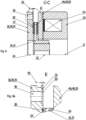
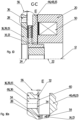
- eine Draufsicht eines ersten Ausführungsbeispiels einer Bremseinheit mit eingezeichneten Teilschnitten C-C und D-D,
- Figur 2
- eine Schnittansicht des in
Fig. 1 gezeigten Ausführungsbeispiels, - Figur 3
- eine Ansicht des in
Fig. 1 eingezeichneten Teilschnitts C-C mit eingezeichnetem Detail E, - Figur 3a
- eine Ansicht des in
Fig. 3 eingezeichneten Details E, - Figur 4
- eine Ansicht des in
Fig. 1 eingezeichneten Teilschnitts D-D mit eingezeichnetem Detail F, - Figur 4a
- eine Ansicht des in
Fig. 4 eingezeichneten Details F, - Figur 5
- eine Draufsicht eines zweiten Ausführungsbeispiels einer Bremseinheit mit eingezeichneten Teilschnitten C-C, D-D und G-G,
- Figur 6
- eine Ansicht des in
Fig. 5 eingezeichneten Teilschnitts C-C mit eingezeichnetem Detail E, - Figur 6a
- eine Ansicht des in
Fig. 6 eingezeichneten Details E, - Figur 7
- eine Ansicht des in
Fig. 5 eingezeichneten Teilschnitts D-D mit eingezeichnetem Detail F, - Figur 7a
- eine Ansicht des in
Fig. 7 eingezeichneten Details F, - Figur 8
- eine Ansicht des in
Fig. 5 eingezeichneten Teilschnitts G-G mit eingezeichnetem Detail H, - Figur 8a
- eine Ansicht des in
Fig. 8 eingezeichneten Details H, - Figur 9
- eine Draufsicht eines dritten Ausführungsbeispiels einer Bremseinheit mit eingezeichneten Teilschnitten C-C, D-D und G-G,
- Figur 10
- eine Ansicht des in
Fig. 9 eingezeichneten Teilschnitts C-C mit eingezeichnetem Detail E, - Figur 10a
- eine Ansicht des in
Fig. 10 eingezeichneten Details E, - Figur 11
- eine Ansicht des in
Fig. 9 eingezeichneten Teilschnitts D-D mit eingezeichnetem Detail F, - Figur 11a
- eine Ansicht des in
Fig. 11 eingezeichneten Details F, - Figur 12
- eine Ansicht des in
Fig. 9 eingezeichneten Teilschnitts G-G mit eingezeichnetem Detail H, - Figur 12a
- eine Ansicht des in
Fig. 12 eingezeichneten Details H. - Die
Figuren 1 bis 12a zeigen verschiedene Ansichten verschiedener Ausführungsbeispiele. Für gleiche und funktionsgleiche Teile werden die gleichen Bezugszeichen verwendet. Der Übersichtlichkeit halber werden nicht alle Bezugszeichen in jeder Figur verwendet. - Die
Fig. 1 bis 4a zeigen verschiedene Ansichten eines ersten Ausführungsbeispiels einer als Federdruckbremse 11 ausgebildeten Bremseinheit 10. Die Erfindung soll zunächst exemplarisch anhand dieses Ausführungsbeispiels erläutert werden. Was das zweite und das dritte Ausführungsbeispiel betrifft, soll im Folgenden dargestellt werden, worin diese sich von dem ersten Ausführungsbeispiel unterscheiden. - Einen Überblick über die Komponenten der Bremseinheit 10 zeigt
Fig. 2 . Die Bremseinheit 10 umfasst eine Einheitslängsachse 12, ein als Rotor 13 ausgebildetes erstes Bremselement 14, ein als Stator 15 ausgebildetes zweites Bremselement 16 und ein Gehäuse 20. Das erste Bremselement 14 ist dabei auf einer nicht dargestellten, auf der Einheitslängsachse 12 angeordneten, zu bremsenden Welle angeordnet. Eine erste Elementlängsachse 22 des ersten Bremselements 14 und eine zweite Elementlängsachse 24 des zweiten Bremselements 16 sind entlang der Einheitslängsachse 12 derart hintereinander angeordnet, dass die erste Elementlängsachse 22 und die zweite Elementlängsachse 24 jeweils auf der und parallel zu der Einheitslängsachse 12 angeordnet sind. Das zweite Bremselement 16 ist scheibenförmig als Rotationskörper um die zweite Elementlängsachse 24 ausgebildet, und weist darüber hinaus eine erste, senkrecht zur zweiten Elementlängsachse 24 angeordnete Stirnseite 26 auf. Das zweite Bremselement 16 weist außerdem eine Bremsfläche 28 sowie drei Anlagesektionen 29 mit jeweils einer Vielzahl an unterschiedlichen Anlageflächen, nämlich einer ersten Anlagefläche 30, einer zweiten Anlagefläche 32 und einer dritten Anlagefläche 34, auf. Die Anlageflächen 30, 32, 34 sind insbesondere inFig. 1 dargestellt. Die Anlageflächen 30, 32, 34 sind ebenso wie die Bremsfläche 28 auf der ersten Stirnseite 26 angeordnet. Damit sind die Anlageflächen 30, 32, 34 und die Bremsflächen auf derselben Stirnseite des zweiten Bremselements 16 angeordnet. - Das zweite Bremselement 16 ist mittels jeder der Anlageflächen 30, 32, 34 mit dem Gehäuse 20 fest koppelbar. Damit ist das zweite Bremselement 16 insbesondere drehfest mit dem Gehäuse 20 koppelbar. Die Bremsfläche kann bei Kopplung einer der Anlageflächen 30, 32, 34 mit dem Gehäuse 20 mit dem ersten Bremselement 14 zur Erzeugung einer Bremswirkung in Wirkverbindung gebracht werden.
- Zur Kopplung des zweiten Bremselements 16 mit dem Gehäuse 20 weist das zweite Bremselement 16 mehrere Kopplungsbohrungen 36 auf. Wie aus
Fig. 2 erkennbar ist, sind die Kopplungsbohrungen 36 als Durchgangsbohrung zur Durchführung jeweils einer Kopplungsschraube 38 ausgebildet, mit der die Bremseinheit 10 beispielsweise an einem nicht dargestellten, inFig. 2 links der Bremseinheit 10 anzuordnenden Motorflansch befestigbar ist. Bei einer derartigen Anordnung liegt das zweite Bremselement 16 vorzugsweise mit einer zweiten Stirnseite 37 an dem Motorflansch an. Die zweite Stirnseite 37 ist gegenüber der ersten Stirnseite 26 angeordnet. Das zweite Bremselement 16 ist in diesem Fall als Bremsenflansch 39 ausgebildet und kann zwischen dem Gehäuse 20 und dem Motorflansch eingeklemmt und so mit dem Gehäuse 20 gekoppelt werden. Die Kopplung kann so zerstörungsfrei lösbar ausgebildet sein. Zwischen dem zweiten Bremselement 16 und dem Gehäuse 20 sind im vorliegenden Ausführungsbeispiel zusätzliche Bauteile in Form von Distanzhülsen 40 angeordnet. - Wie
Fig. 1 zeigt ist jede der Kopplungsbohrungen 36 in einer der Anlageflächen 30, 32, 34 angeordnet. Dadurch kann das Aufbringen eines Biegemoments auf das zweite Bremselement 16 durch die angezogenen Kopplungsschrauben 38 vermieden werden. Die Kopplungsbohrungen 36 sind auf einem gedachten Kopplungskreis 42 angeordnet, der auf der ersten Stirnseite 26 des zweiten Bremselements 16 angeordnet ist. Ein Kopplungskreismittelpunkt 44 des Kopplungskreises 42 ist auf der zweiten Elementlängsachse 24 angeordnet. -
Fig. 2 zeigt weiter, dass das erste Bremselement 14 zwischen dem zweiten Bremselement 16 und einem dritten Bremselement 46 angeordnet ist, das ebenfalls als Stator 15 ausgebildet ist. Das dritte Bremselement 46 ist als Anker 48 der Federdruckbremse 11 ausgebildet und ist zur Betätigung der Bremseinheit 10 entlang der Einheitslängsachse 12 axial verschiebbar. Auf das dritte Bremselement 46 kann durch einen im Gehäuse 20 angeordneten Elektromagneten 50 eine Kraft ausgeübt werden, die die Bremseinheit 10 entgegen der Kraft von ebenfalls im Gehäuse 20 angeordneten Druckfedern 52 offen hält. - Durch Verschieben des dritten Bremselements 46 in Richtung des ersten Bremselements 14 kann ein bremsender Reibkontakt zwischen dem ersten Bremselement 14 und dem dritten Bremselement 46 sowie zwischen dem ersten Bremselement 14 und dem zweiten Bremselement 16 ausgebildet werden. Dafür ist auch das zweite Bremselement 16 entlang der Einheitslängsachse 12 axial verschiebbar angeordnet. Entsprechend dem zweiten Bremselement 16 weist das dritte Bremselement 46 dafür ebenfalls eine Bremsfläche 53 auf. An dem ersten Bremselement 14 ist an den dem zweiten Bremselement 16 und den dem dritten Bremselement 46 zugewandten Flächen jeweils mindestens ein Reibbelag 54 angeordnet, der dafür vorgesehen ist, mit den jeweiligen Bremsflächen 28, 53 des zweiten Bremselements 16 und des dritten Bremselements 46 in Reibkontakt zu treten.
- Die erste Anlagefläche 30, die zweite Anlagefläche 32 und die dritte Anlagefläche 34 jeder der Anlagesektionen 29 unterscheiden sich darin, dass sie zu der Bremsfläche 28 des zweiten Bremselements 16 entlang der zweiten Elementlängsachse 24 unterschiedliche Abstände aufweisen. So weist jede der ersten Anlageflächen 30 einen ersten Abstand, jede der zweiten Anlageflächen 32 einen zweiten Abstand 56 und jede der dritten Anlageflächen 34 einen dritten Abstand 58 zu der Bremsfläche 28 auf. Der zweite Abstand 56 ist in den
Fig. 3 u. 3a und der dritte Abstand 58 in denFig. 4 u. 4a gezeigt. Der erste Abstand ist beispielsweise inFig. 8a u. 12a erkennbar. -
Fig. 1 veranschaulicht, dass die unterschiedlichen Anlageflächen 30, 32, 34 nicht gleichzeitig mit dem Gehäuse 20 koppelbar sind. Durch die Verwendung der unterschiedlichen Anlageflächen 30, 32, 34 zur Kopplung des zweiten Bremselements 16 mit dem Gehäuse 20 kann so die Bremsfläche 28 des zweiten Bremselements 16 unterschiedlich nahe an dem ersten Bremselement 14 angeordnet werden. Damit kann eine Breite eines Luftspalts, der bei geöffneter Bremseinheit 10 insbesondere zwischen dem ersten Bremselement 14 und dem zweiten Bremselement 16 angeordnet ist, verstellt werden. Die Abstände liegen typischerweise im Bereich von 0 bis 1 mm. So kann beispielsweise der erste Abstand 0 mm betragen und der dritte Abstand 58 im Bereich von 0,5 bis 1 mm liegen. - Wie insbesondere in den
Fig. 3a u. 4a zu erkennen ist, sind insbesondere die zweite Anlagefläche 32 und die dritte Anlagefläche 34 jeweils in einer Ausnehmung 60 des zweiten Bremselements 16 angeordnet. Die dritte Anlagefläche 34 ist dementsprechend tiefer in dem zweiten Bremselement 16 angeordnet als die zweite Anlagefläche 32. Dabei sind die Anlageflächen 30, 32, 34 parallel zu der Bremsfläche 28 angeordnet. Durch Verschieben und Anordnen des zweiten Bremselements 16 derart, dass anstatt der ersten Anlagefläche 30 die zweite Anlagefläche 32 oder die dritte Anlagefläche 34 mit dem Gehäuse 20 gekoppelt ist, kann das verschleißbedingte Abnehmen des mindestens einen Reibbelags 54, zumindest teilweise, ausgeglichen werden. - In
Fig. 1 ist erkennbar, dass die Anlageflächen 30, 32, 34 auf dem Kopplungskreis 42 angeordnet sind. Dadurch kann durch ein Verdrehen des zweiten Bremselements 16 gegenüber dem Gehäuse 20 um den Kopplungskreismittelpunkt 44 die mit dem Gehäuse 20 zu koppelnde der Anlageflächen 30, 32, 34 ausgewählt werden. Die Anlageflächen 30, 32, 34 jeder der Anlagesektionen 29 sind nach ihrem jeweiligen Abstand zur Bremsfläche 28 in Umfangsrichtung um die zweite Elementlängsachse 24 aufsteigend geordnet angeordnet. So kann durch ein schrittweises Weiterdrehen des zweiten Bremselements 16 gegenüber dem Gehäuse 20 der Luftspalt stufenweise verstellt werden. - Jede der Anlagesektionen 29 ist identisch ausgebildet. Die Anlagesektionen 29 sind bezüglich der zweiten Elementlängsachse 24 winklig versetzt zueinander angeordnet und weisen damit einen winkligen Sektionsversatz 62 zueinander auf. Die drei Anlagesektionen 29 sind gleichmäßig zueinander versetzt angeordnet. Der Sektionsversatz 62 beträgt dementsprechend 120°.
- Die Anlageflächen 30, 32, 34 jeder der Anlagesektionen 29 sind bezüglich der zweiten Elementlängsachse 24 ebenfalls winklig versetzt zueinander angeordnet und weisen damit einen winkligen Flächenversatz 64 zueinander auf. Der Flächenversatz 64 liegt bevorzugt im Bereich von 10° bis 30°, besonders bevorzugt im Bereich von 15° bis 25°. Der Sektionsversatz 62 zwischen den identischen der Anlageflächen 30, 32, 34 verschiedener der Anlagesektionen 29 ist damit größer als der Flächenversatz 64 zwischen den unterschiedlichen der Anlageflächen 30, 32, 34 einer der Anlagesektionen 29.
- Bei dem in den
Fig. 1-4a gezeigten ersten Ausführungsbeispiel sind die Anlageflächen 30, 32, 34 einer jeden Anlagesektion 29 beabstandet zueinander, also räumlich getrennt voneinander angeordnet (siehe insbesondereFig. 1 ). Im zweiten (Fig. 5-8a ) sowie dritten (Fig. 9-12a ) Ausführungsbeispiel sind die Anlageflächen 30, 32, 34 jeder der Anlagesektionen 29 hingegen unmittelbar aneinander angrenzend angeordnet sein (siehe insbesondereFig. 5 ,8 u. 8a). Damit ergibt sich eine treppenstufenartige Anordnung der Anlageflächen 30, 32, 34 jeder der Anlagesektionen 29. So kann die Luftspaltverstellung mit vergleichsweise geringem axialem Spiel ermöglicht werden. - Das dritte, in den
Fig. 9-12a dargestellte Ausführungsbeispiel zeichnet sich zusätzlich dadurch aus, dass die Kopplungsbohrungen 36 als Langloch 66 ausgebildet sind. Dadurch kann der Luftspalt verstellt werden, ohne dass die Kopplungsschrauben 38 entnommen werden müssen. Jedes der Langlöcher 66 erstreckt sich entlang des Kopplungskreises 42 über alle Anlageflächen 30, 32, 34 der jeweiligen Anlagesektion 29. - Ein Verfahren zur Luftspaltverstellung bei einem der zuvor beschriebenen Ausführungsbeispiele der Bremseinheit 10 umfasst die folgenden wesentlichen Schritte:
- Entkoppeln des Gehäuses 20 von dem zweiten Bremselement 16,
- Verdrehen des zweiten Bremselements 16 um die zweite Einheitslängsachse 12 gegenüber dem Gehäuse 20,
- Koppeln des Gehäuses 20 mit dem zweiten Bremselement 16.
- Zum Entkoppeln des Gehäuses 20 werden die Kopplungsschrauben 38 gelöst. Im Falle des ersten Ausführungsbeispiels (
Fig. 1-4a ) und des zweiten Ausführungsbeispiels (Fig. 5-8a ) werden anschließend die Kopplungsschrauben 38 zumindest aus den Kopplungsbohrungen 36 des zweiten Bremselements 16 entfernt. Beim dritten Ausführungsbeispiel (Fig. 9-12a ) können die gelösten Kopplungsschrauben 38 aufgrund der Langlöcher 66 hingegen in den Kopplungsbohrungen 36 des zweiten Bremselements 16 verbleiben. Daraufhin kann das zweite Bremselement 16 um die Einheitslängsachse 12 gegenüber dem Gehäuse 20 verdreht werden, sodass das Gehäuse 20 in jeder der Anlagesektionen 29 mit einer anderen der Anlageflächen 30, 32, 34 als zuvor mit dem zweiten Bremselement 16 gekoppelt werden kann. Dazu wird das zweite Bremselement 16 zumindest um den einfachen Flächenversatz 64 verdreht. Anschließend kann der Zusammenbau in der entsprechend umgekehrten Reihenfolge erfolgen. Bei diesem Verfahren zur Verstellung des Luftspalts muss das zweite Bremselement 16 nicht weiter, insbesondere nicht von der Welle, demontiert werden. Ein derartiges Vorgehen kann demnach insbesondere dann von Vorteil sein, wenn die Bremseinheit 10 vom zweiten Bremselement 16 her unzugänglich ist, beispielsweise weil dort ein Motor angeordnet ist. -
- 10
- Bremseinheit
- 11
- Federdruckbremse
- 12
- Einheitslängsachse
- 13
- Rotor
- 14
- erstes Bremselement
- 15
- Stator
- 16
- zweites Bremselement
- 20
- Gehäuse
- 22
- erste Elementlängsachse
- 24
- zweite Elementlängsachse
- 26
- erste Stirnseite
- 28
- Bremsfläche
- 29
- Anlagesektion
- 30
- erste Anlagefläche
- 32
- zweite Anlagefläche
- 34
- dritte Anlagefläche
- 36
- Kopplungsbohrung
- 37
- zweite Stirnseite
- 38
- Kopplungsschraube
- 39
- Bremsenflansch
- 40
- Distanzhülse
- 42
- Kopplungskreis
- 44
- Kopplungskreismittelpunkt
- 46
- drittes Bremselement
- 48
- Anker
- 50
- Elektromagnet
- 52
- Druckfeder
- 53
- Bremsfläche
- 54
- Reibbelag
- 56
- zweiter Abstand
- 58
- dritter Abstand
- 60
- Ausnehmung
- 62
- Sektionsversatz
- 64
- Flächenversatz
- 66
- Langloch
Claims (15)
- Bremseinheit (10), umfassend:• eine Einheitslängsachse (12),• ein erstes Bremselement (14) mit einer ersten Elementlängsachse (22),• ein zweites Bremselement (16) mit einer zweiten Elementlängsachse (24), einer ersten Stirnseite (26), einer Bremsfläche (28) und einer Vielzahl an unterschiedlichen Anlageflächen (30, 32, 34),
und• ein Gehäuse (20),
wobei• die Anlageflächen (30, 32, 34) auf der ersten Stirnseite (26) des zweiten Bremselements (16) angeordnet sind,• das zweite Bremselement(16) mittels jeder der Anlageflächen (30, 32, 34) mit dem Gehäuse (20) fest koppelbar ist,• die Bremsfläche (28) bei Kopplung einer der Anlageflächen (30, 32, 34) mit dem Gehäuse (20) mit dem ersten Bremselement (14) in Wirkverbindung bringbar ist,
und• sich die unterschiedlichen Anlageflächen (30, 32, 34) darin unterscheiden, dass sie zu der Bremsfläche (28) entlang der zweiten Elementlängsachse (24) unterschiedliche Abstände (56, 58) aufweisen. - Bremseinheit nach Anspruch 1, dadurch gekennzeichnet, dass das erste Bremselement (14) und das zweite Bremselement (16) entlang der Einheitslängsachse (12) derart hintereinander angeordnet sind, dass die erste Elementlängsachse (22) und die zweite Elementlängsachse (24) jeweils auf der und parallel zu der Einheitslängsachse (12) angeordnet sind.
- Bremseinheit nach einem der vorhergehenden Ansprüche, dadurch gekennzeichnet, dass auf der ersten Stirnseite (26) des zweiten Bremselements (16) um die zweite Elementlängsachse (24) ein gedachter Kopplungskreis (42) angeordnet ist, wobei die Anlageflächen (30, 32, 34) auf dem Kopplungskreis (42) angeordnet sind.
- Bremseinheit nach einem der vorhergehenden Ansprüche, dadurch gekennzeichnet, dass das zweite Bremselement (16) mindestens eine Anlagesektion (29) aufweist, die jeweils eine der unterschiedlichen Anlageflächen (30, 32, 34) umfasst.
- Bremseinheit nach Anspruch 4, dadurch gekennzeichnet, dass die unterschiedlichen Anlageflächen (30, 32, 34) der mindestens einen Anlagesektion (29) beabstandet zueinander oder unmittelbar aneinander angrenzend angeordnet sind.
- Bremseinheit nach einem der Ansprüche 4 bis 5, dadurch gekennzeichnet, dass das die mindestens eine Anlagesektion (29) mehrere, vorzugsweise beabstandet zueinander angeordnete, Anlagesektionen (29) umfasst.
- Bremseinheit nach einem der vorhergehenden Ansprüche, dadurch gekennzeichnet, dass das zweite Bremselement (16) mindestens eine Kopplungsbohrung (36) zur Kopplung des zweiten Bremselements (16) mit dem Gehäuse (20) aufweist.
- Bremseinheit nach Anspruch 7, dadurch gekennzeichnet, dass die mindestens eine Kopplungsbohrung (36) in mindestens einer der Anlageflächen (30, 32, 34) angeordnet ist.
- Bremseinheit nach einem der Ansprüche 7 bis 8, dadurch gekennzeichnet, dass die mindestens eine Kopplungsbohrung (36) als Langloch (66) ausgebildet ist.
- Bremseinheit nach einem der vorhergehenden Ansprüche, dadurch gekennzeichnet, dass das erste Bremselement (14) als Rotor (13) und das zweite Bremselement (16) als Stator (15) ausgebildet ist.
- Bremseinheit nach einem der vorhergehenden Ansprüche, dadurch gekennzeichnet, dass das erste Bremselement (14) zwischen dem zweiten Bremselement (16) und einem, vorzugsweise als Stator (15) ausgebildeten, dritten Bremselement (46) angeordnet ist, wobei das dritte Bremselement (46) entlang der Einheitslängsachse (12) axial verschiebbar ist.
- Bremseinheit nach einem der vorhergehenden Ansprüche, dadurch gekennzeichnet, dass die Bremseinheit (10) als Federdruckbremse (11) oder Permanentmagnetbremse ausgebildet ist.
- Bremseinheit nach den Ansprüchen 11 und 12, dadurch gekennzeichnet, dass das zweite Bremselement (16) als Bremsenflansch (39) und/oder das dritte Bremselement (46) als Anker (48) ausgebildet ist.
- Motor-Bremsen-Kombination, umfassend einen Motor mit einem Motorflansch sowie eine Bremseinheit (10) nach einem der vorhergehenden Ansprüche, wobei das zweite Bremselement (16) mit einer zweiten Stirnseite (37) dem Motorflansch zugewandt mit dem Motorflansch fest koppelbar ist.
- Verfahren zur Luftspaltverstellung bei einer Bremseinheit (10) nach einem der Ansprüche 1 bis 13 oder bei einer Motor-Bremsen-Kombination nach Anspruch 14 mit folgenden Schritten:• Entkoppeln des Gehäuses (20) von dem zweiten Bremselement (16),• Verdrehen des zweiten Bremselements (16) um die Einheitslängsachse (12) gegenüber dem Gehäuse (20),• Koppeln des Gehäuses (20) mit dem zweiten Bremselement (16).
Priority Applications (1)
| Application Number | Priority Date | Filing Date | Title |
|---|---|---|---|
| EP23192093.5A EP4509737B1 (de) | 2023-08-18 | 2023-08-18 | Bremseinheit, motor-bremsen-kombination sowie verfahren zur luftspaltverstellung |
Applications Claiming Priority (1)
| Application Number | Priority Date | Filing Date | Title |
|---|---|---|---|
| EP23192093.5A EP4509737B1 (de) | 2023-08-18 | 2023-08-18 | Bremseinheit, motor-bremsen-kombination sowie verfahren zur luftspaltverstellung |
Publications (2)
| Publication Number | Publication Date |
|---|---|
| EP4509737A1 true EP4509737A1 (de) | 2025-02-19 |
| EP4509737B1 EP4509737B1 (de) | 2025-12-31 |
Family
ID=87748162
Family Applications (1)
| Application Number | Title | Priority Date | Filing Date |
|---|---|---|---|
| EP23192093.5A Active EP4509737B1 (de) | 2023-08-18 | 2023-08-18 | Bremseinheit, motor-bremsen-kombination sowie verfahren zur luftspaltverstellung |
Country Status (1)
| Country | Link |
|---|---|
| EP (1) | EP4509737B1 (de) |
Citations (6)
| Publication number | Priority date | Publication date | Assignee | Title |
|---|---|---|---|---|
| DE1920128A1 (de) | 1969-04-21 | 1970-11-05 | Lenze Kg Maschf Hans | Selbsttaetige Nachstellvorrichtung fuer Zweischeibenoder Lamellen-Federkraft-Kupplungen oder -Bremsen mit elektromagnetischer Loesung der Kupplung bzw. Lueftung der Bremse |
| US3665231A (en) * | 1969-03-21 | 1972-05-23 | Baumueller Gmbh A | Automatically adjustable single disc brake for motors |
| DE7822318U1 (de) * | 1977-08-29 | 1979-02-15 | Warner Electric Brake & Clutch Co., Beloit, Wis. (V.St.A.) | Elektromagnetische bremse |
| US4982825A (en) | 1989-05-11 | 1991-01-08 | Sepal | Torque and air gap adjustment mechanism for spring engaged brake or clutch |
| DE102013219878B3 (de) * | 2013-10-01 | 2015-03-12 | Kendrion (Villingen) Gmbh | Elektromagnetisch betätigbare Federdruckbremse sowie Verfahren zur Herstellung derselben |
| DE202016003948U1 (de) * | 2016-06-24 | 2017-09-27 | Intorq Gmbh & Co. Kg | Bremse und Antriebssystem mit Bremse |
-
2023
- 2023-08-18 EP EP23192093.5A patent/EP4509737B1/de active Active
Patent Citations (7)
| Publication number | Priority date | Publication date | Assignee | Title |
|---|---|---|---|---|
| US3665231A (en) * | 1969-03-21 | 1972-05-23 | Baumueller Gmbh A | Automatically adjustable single disc brake for motors |
| DE1920128A1 (de) | 1969-04-21 | 1970-11-05 | Lenze Kg Maschf Hans | Selbsttaetige Nachstellvorrichtung fuer Zweischeibenoder Lamellen-Federkraft-Kupplungen oder -Bremsen mit elektromagnetischer Loesung der Kupplung bzw. Lueftung der Bremse |
| US3613849A (en) * | 1969-04-21 | 1971-10-19 | Lenze Kg Maschf Hans | Automatic adjusting device for clutches and brakes |
| DE7822318U1 (de) * | 1977-08-29 | 1979-02-15 | Warner Electric Brake & Clutch Co., Beloit, Wis. (V.St.A.) | Elektromagnetische bremse |
| US4982825A (en) | 1989-05-11 | 1991-01-08 | Sepal | Torque and air gap adjustment mechanism for spring engaged brake or clutch |
| DE102013219878B3 (de) * | 2013-10-01 | 2015-03-12 | Kendrion (Villingen) Gmbh | Elektromagnetisch betätigbare Federdruckbremse sowie Verfahren zur Herstellung derselben |
| DE202016003948U1 (de) * | 2016-06-24 | 2017-09-27 | Intorq Gmbh & Co. Kg | Bremse und Antriebssystem mit Bremse |
Also Published As
| Publication number | Publication date |
|---|---|
| EP4509737B1 (de) | 2025-12-31 |
Similar Documents
| Publication | Publication Date | Title |
|---|---|---|
| CH698337B1 (de) | Anordnung mit einem Halterungssystem zur Halterung zweier Maschinenbauteile. | |
| WO2012104242A1 (de) | Vorrichtung zur veränderung der relativen winkellage einer nockenwelle gegenüber einer kurbelwelle einer brennkraftmaschine | |
| DE102012023437A1 (de) | Rundlaufoptimiertes Werkzeugspannsystem für Dentalwinkelhandstücke und Dentalturbinen | |
| EP3567708B1 (de) | Sekundärteil für einen eisenlosen linearmotor | |
| EP1217209A2 (de) | Verstellvorrichtung zum Verstellen eines auf das Verdrängungsvolumen einer hydrostatischen Maschine einwirkenden Stellkolbens | |
| DE2211453C3 (de) | Führung für den Sattel einer Schwimmsattel-Scheibenbremse am Bremsträger | |
| DE2211429B2 (de) | Führung für den Sattel einer Schwimmsattel-Scheibenbremse am Bremsträger | |
| EP3234389B1 (de) | Kupplungselement und kupplungsanordnung zur axialen drehmomentübertragung, und lamellenanordnung für solche | |
| DE10311572B4 (de) | Anordnung zur Verbindung eines rohrförmigen Elementes mit einem darin erstreckten Körper | |
| EP3721113B1 (de) | Lagerkonstruktion aus einzeln montierbaren und austauschbaren elastomerlager-elementen | |
| EP1790437A2 (de) | Vorrichtung zum Einpressen eines auf einer Radnabe sitzenden Radlagers | |
| EP4509737B1 (de) | Bremseinheit, motor-bremsen-kombination sowie verfahren zur luftspaltverstellung | |
| DE3146790A1 (de) | "scheibenbremse" | |
| DE202013002597U1 (de) | Elektromagnetische Kupplungsvorrichtung | |
| DE102023122157B3 (de) | Bremseinheit, Motor-Bremsen-Kombination sowie Verfahren zu Luftspaltverstellung | |
| DE102010026728A1 (de) | Bremsscheibe und Montageverfahren | |
| DE4126194A1 (de) | Festsattel mit abstuetzungen fuer beide bremskloetze in einem gehaeuseteil | |
| EP3625474B1 (de) | Anordnung einer scheibenbremse für ein nutzfahrzeug | |
| DE2756856A1 (de) | Schwimmsattel-scheibenbremse | |
| EP2197092A1 (de) | Verfahren zum Montieren eines Resolvers und elektrische Maschine | |
| DE102023123149A1 (de) | Drehmomentmodul für eine Federkraftbremse sowie Federkraftbremse | |
| DE102015215492A1 (de) | Verfahren zum Herstellen einer variablen Turbinengeometrie eines Abgasturboladers | |
| DE20303060U1 (de) | Motoranbaubremse | |
| EP0761915A2 (de) | Schliesszylinder | |
| EP4083353B1 (de) | Rückplattenbaugruppe für einen türbeschlag und türbeschlag |
Legal Events
| Date | Code | Title | Description |
|---|---|---|---|
| PUAI | Public reference made under article 153(3) epc to a published international application that has entered the european phase |
Free format text: ORIGINAL CODE: 0009012 |
|
| STAA | Information on the status of an ep patent application or granted ep patent |
Free format text: STATUS: THE APPLICATION HAS BEEN PUBLISHED |
|
| AK | Designated contracting states |
Kind code of ref document: A1 Designated state(s): AL AT BE BG CH CY CZ DE DK EE ES FI FR GB GR HR HU IE IS IT LI LT LU LV MC ME MK MT NL NO PL PT RO RS SE SI SK SM TR |
|
| STAA | Information on the status of an ep patent application or granted ep patent |
Free format text: STATUS: REQUEST FOR EXAMINATION WAS MADE |
|
| 17P | Request for examination filed |
Effective date: 20250429 |
|
| GRAP | Despatch of communication of intention to grant a patent |
Free format text: ORIGINAL CODE: EPIDOSNIGR1 |
|
| STAA | Information on the status of an ep patent application or granted ep patent |
Free format text: STATUS: GRANT OF PATENT IS INTENDED |
|
| RIC1 | Information provided on ipc code assigned before grant |
Ipc: F16D 55/28 20060101AFI20250626BHEP |
|
| INTG | Intention to grant announced |
Effective date: 20250730 |
|
| GRAS | Grant fee paid |
Free format text: ORIGINAL CODE: EPIDOSNIGR3 |
|
| GRAA | (expected) grant |
Free format text: ORIGINAL CODE: 0009210 |
|
| STAA | Information on the status of an ep patent application or granted ep patent |
Free format text: STATUS: THE PATENT HAS BEEN GRANTED |
|
| AK | Designated contracting states |
Kind code of ref document: B1 Designated state(s): AL AT BE BG CH CY CZ DE DK EE ES FI FR GB GR HR HU IE IS IT LI LT LU LV MC ME MK MT NL NO PL PT RO RS SE SI SK SM TR |
|
| REG | Reference to a national code |
Ref country code: CH Ref legal event code: F10 Free format text: ST27 STATUS EVENT CODE: U-0-0-F10-F00 (AS PROVIDED BY THE NATIONAL OFFICE) Effective date: 20251231 Ref country code: GB Ref legal event code: FG4D Free format text: NOT ENGLISH |
|
| REG | Reference to a national code |
Ref country code: DE Ref legal event code: R096 Ref document number: 502023002631 Country of ref document: DE |
|
| REG | Reference to a national code |
Ref country code: IE Ref legal event code: FG4D Free format text: LANGUAGE OF EP DOCUMENT: GERMAN |
|
| REG | Reference to a national code |
Ref country code: LT Ref legal event code: MG9D |
|
| PG25 | Lapsed in a contracting state [announced via postgrant information from national office to epo] |
Ref country code: NO Free format text: LAPSE BECAUSE OF FAILURE TO SUBMIT A TRANSLATION OF THE DESCRIPTION OR TO PAY THE FEE WITHIN THE PRESCRIBED TIME-LIMIT Effective date: 20260331 |
|
| PG25 | Lapsed in a contracting state [announced via postgrant information from national office to epo] |
Ref country code: FI Free format text: LAPSE BECAUSE OF FAILURE TO SUBMIT A TRANSLATION OF THE DESCRIPTION OR TO PAY THE FEE WITHIN THE PRESCRIBED TIME-LIMIT Effective date: 20251231 Ref country code: HR Free format text: LAPSE BECAUSE OF FAILURE TO SUBMIT A TRANSLATION OF THE DESCRIPTION OR TO PAY THE FEE WITHIN THE PRESCRIBED TIME-LIMIT Effective date: 20251231 |
|
| PG25 | Lapsed in a contracting state [announced via postgrant information from national office to epo] |
Ref country code: RS Free format text: LAPSE BECAUSE OF FAILURE TO SUBMIT A TRANSLATION OF THE DESCRIPTION OR TO PAY THE FEE WITHIN THE PRESCRIBED TIME-LIMIT Effective date: 20260331 |