EP4509802A1 - Procédé de production de quantités dosées individuelles à l'aide d'un cylindre de dosage - Google Patents
Procédé de production de quantités dosées individuelles à l'aide d'un cylindre de dosage Download PDFInfo
- Publication number
- EP4509802A1 EP4509802A1 EP23191975.4A EP23191975A EP4509802A1 EP 4509802 A1 EP4509802 A1 EP 4509802A1 EP 23191975 A EP23191975 A EP 23191975A EP 4509802 A1 EP4509802 A1 EP 4509802A1
- Authority
- EP
- European Patent Office
- Prior art keywords
- time period
- dosing
- overpressure
- ejection
- roller
- Prior art date
- Legal status (The legal status is an assumption and is not a legal conclusion. Google has not performed a legal analysis and makes no representation as to the accuracy of the status listed.)
- Pending
Links
Images

Classifications
-
- G—PHYSICS
- G01—MEASURING; TESTING
- G01F—MEASURING VOLUME, VOLUME FLOW, MASS FLOW OR LIQUID LEVEL; METERING BY VOLUME
- G01F11/00—Apparatus requiring external operation adapted at each repeated and identical operation to measure and separate a predetermined volume of fluid or fluent solid material from a supply or container, without regard to weight, and to deliver it
- G01F11/10—Apparatus requiring external operation adapted at each repeated and identical operation to measure and separate a predetermined volume of fluid or fluent solid material from a supply or container, without regard to weight, and to deliver it with measuring chambers moved during operation
- G01F11/12—Apparatus requiring external operation adapted at each repeated and identical operation to measure and separate a predetermined volume of fluid or fluent solid material from a supply or container, without regard to weight, and to deliver it with measuring chambers moved during operation of the valve type, i.e. the separating being effected by fluid-tight or powder-tight movements
- G01F11/20—Apparatus requiring external operation adapted at each repeated and identical operation to measure and separate a predetermined volume of fluid or fluent solid material from a supply or container, without regard to weight, and to deliver it with measuring chambers moved during operation of the valve type, i.e. the separating being effected by fluid-tight or powder-tight movements wherein the measuring chamber rotates or oscillates
- G01F11/24—Apparatus requiring external operation adapted at each repeated and identical operation to measure and separate a predetermined volume of fluid or fluent solid material from a supply or container, without regard to weight, and to deliver it with measuring chambers moved during operation of the valve type, i.e. the separating being effected by fluid-tight or powder-tight movements wherein the measuring chamber rotates or oscillates for fluent solid material
-
- B—PERFORMING OPERATIONS; TRANSPORTING
- B65—CONVEYING; PACKING; STORING; HANDLING THIN OR FILAMENTARY MATERIAL
- B65B—MACHINES, APPARATUS OR DEVICES FOR, OR METHODS OF, PACKAGING ARTICLES OR MATERIALS; UNPACKING
- B65B1/00—Packaging fluent solid material, e.g. powders, granular or loose fibrous material, loose masses of small articles, in individual containers or receptacles, e.g. bags, sacks, boxes, cartons, cans, or jars
- B65B1/30—Devices or methods for controlling or determining the quantity or quality or the material fed or filled
- B65B1/36—Devices or methods for controlling or determining the quantity or quality or the material fed or filled by volumetric devices or methods
- B65B1/363—Devices or methods for controlling or determining the quantity or quality or the material fed or filled by volumetric devices or methods with measuring pockets moving in an endless path
-
- A—HUMAN NECESSITIES
- A61—MEDICAL OR VETERINARY SCIENCE; HYGIENE
- A61J—CONTAINERS SPECIALLY ADAPTED FOR MEDICAL OR PHARMACEUTICAL PURPOSES; DEVICES OR METHODS SPECIALLY ADAPTED FOR BRINGING PHARMACEUTICAL PRODUCTS INTO PARTICULAR PHYSICAL OR ADMINISTERING FORMS; DEVICES FOR ADMINISTERING FOOD OR MEDICINES ORALLY; BABY COMFORTERS; DEVICES FOR RECEIVING SPITTLE
- A61J3/00—Devices or methods specially adapted for bringing pharmaceutical products into particular physical or administering forms
- A61J3/07—Devices or methods specially adapted for bringing pharmaceutical products into particular physical or administering forms into the form of capsules or similar small containers for oral use
- A61J3/071—Devices or methods specially adapted for bringing pharmaceutical products into particular physical or administering forms into the form of capsules or similar small containers for oral use into the form of telescopically engaged two-piece capsules
- A61J3/074—Filling capsules; Related operations
-
- A—HUMAN NECESSITIES
- A61—MEDICAL OR VETERINARY SCIENCE; HYGIENE
- A61J—CONTAINERS SPECIALLY ADAPTED FOR MEDICAL OR PHARMACEUTICAL PURPOSES; DEVICES OR METHODS SPECIALLY ADAPTED FOR BRINGING PHARMACEUTICAL PRODUCTS INTO PARTICULAR PHYSICAL OR ADMINISTERING FORMS; DEVICES FOR ADMINISTERING FOOD OR MEDICINES ORALLY; BABY COMFORTERS; DEVICES FOR RECEIVING SPITTLE
- A61J3/00—Devices or methods specially adapted for bringing pharmaceutical products into particular physical or administering forms
- A61J3/07—Devices or methods specially adapted for bringing pharmaceutical products into particular physical or administering forms into the form of capsules or similar small containers for oral use
-
- B—PERFORMING OPERATIONS; TRANSPORTING
- B65—CONVEYING; PACKING; STORING; HANDLING THIN OR FILAMENTARY MATERIAL
- B65B—MACHINES, APPARATUS OR DEVICES FOR, OR METHODS OF, PACKAGING ARTICLES OR MATERIALS; UNPACKING
- B65B1/00—Packaging fluent solid material, e.g. powders, granular or loose fibrous material, loose masses of small articles, in individual containers or receptacles, e.g. bags, sacks, boxes, cartons, cans, or jars
- B65B1/04—Methods of, or means for, filling the material into the containers or receptacles
- B65B1/06—Methods of, or means for, filling the material into the containers or receptacles by gravity flow
-
- B—PERFORMING OPERATIONS; TRANSPORTING
- B65—CONVEYING; PACKING; STORING; HANDLING THIN OR FILAMENTARY MATERIAL
- B65B—MACHINES, APPARATUS OR DEVICES FOR, OR METHODS OF, PACKAGING ARTICLES OR MATERIALS; UNPACKING
- B65B1/00—Packaging fluent solid material, e.g. powders, granular or loose fibrous material, loose masses of small articles, in individual containers or receptacles, e.g. bags, sacks, boxes, cartons, cans, or jars
- B65B1/30—Devices or methods for controlling or determining the quantity or quality or the material fed or filled
-
- B—PERFORMING OPERATIONS; TRANSPORTING
- B65—CONVEYING; PACKING; STORING; HANDLING THIN OR FILAMENTARY MATERIAL
- B65B—MACHINES, APPARATUS OR DEVICES FOR, OR METHODS OF, PACKAGING ARTICLES OR MATERIALS; UNPACKING
- B65B1/00—Packaging fluent solid material, e.g. powders, granular or loose fibrous material, loose masses of small articles, in individual containers or receptacles, e.g. bags, sacks, boxes, cartons, cans, or jars
- B65B1/30—Devices or methods for controlling or determining the quantity or quality or the material fed or filled
- B65B1/36—Devices or methods for controlling or determining the quantity or quality or the material fed or filled by volumetric devices or methods
-
- B—PERFORMING OPERATIONS; TRANSPORTING
- B65—CONVEYING; PACKING; STORING; HANDLING THIN OR FILAMENTARY MATERIAL
- B65B—MACHINES, APPARATUS OR DEVICES FOR, OR METHODS OF, PACKAGING ARTICLES OR MATERIALS; UNPACKING
- B65B37/00—Supplying or feeding fluent-solid, plastic, or liquid material, or loose masses of small articles, to be packaged
- B65B37/16—Separating measured quantities from supply
- B65B37/20—Separating measured quantities from supply by volume measurement
-
- G—PHYSICS
- G01—MEASURING; TESTING
- G01F—MEASURING VOLUME, VOLUME FLOW, MASS FLOW OR LIQUID LEVEL; METERING BY VOLUME
- G01F25/00—Testing or calibration of apparatus for measuring volume, volume flow or liquid level or for metering by volume
- G01F25/0092—Testing or calibration of apparatus for measuring volume, volume flow or liquid level or for metering by volume for metering by volume
-
- A—HUMAN NECESSITIES
- A61—MEDICAL OR VETERINARY SCIENCE; HYGIENE
- A61J—CONTAINERS SPECIALLY ADAPTED FOR MEDICAL OR PHARMACEUTICAL PURPOSES; DEVICES OR METHODS SPECIALLY ADAPTED FOR BRINGING PHARMACEUTICAL PRODUCTS INTO PARTICULAR PHYSICAL OR ADMINISTERING FORMS; DEVICES FOR ADMINISTERING FOOD OR MEDICINES ORALLY; BABY COMFORTERS; DEVICES FOR RECEIVING SPITTLE
- A61J2200/00—General characteristics or adaptations
- A61J2200/70—Device provided with specific sensor or indicating means
Definitions
- the invention relates to a method for producing individual dosage amounts of a powdery product by means of a roller dosing device.
- powders are processed that have to be provided in precisely measured partial quantities or dosage amounts for the intended dosage form.
- Target containers for example in the form of blisters, capsules or the like, are filled with such measured dosage amounts of a powdered product so that the consumer has the corresponding unit doses available and can take them.
- Such powdery products are transferred in particular on so-called roller dispensers into individually measured dosage quantities, which are then filled into the respective assigned target containers.
- a roller dispenser comprises a dosage roller, which is provided with at least one, usually several, dosage openings on the circumference, whereby the dosage openings are limited on the inside by a filter element and can be subjected to a negative pressure through the filter element. Under the effect of the negative pressure, powder is sucked into the dosage openings, whereby dosage quantities of the powder are formed, the volume of which corresponds to the volume of the respective dosage opening. The dosage quantities formed in this way are then expelled from the dosage openings by means of excess pressure and passed on to the target container.
- dosing using a roller doser is a volumetric dosing.
- the aim is generally to achieve a dosing in which the measured dosing quantity has a certain mass within a permissible tolerance range.
- volumetric dosing it is therefore important that there is as repeatable a relationship as possible between the measured volume and the mass actually achieved.
- AMV Advanced Mass Verification
- the invention is therefore based on the object of specifying a method by means of which the individual masses produced by a roller dosing device can be ejected and tested in a simple, controlled manner.
- the comparison of the actual time period with the at least one target time period is used to monitor process limits and as an error reaction. If the filter element slowly becomes clogged over time, the blow-out effect of a fixed discharge overpressure is reduced. The release of the powder quantity from the dosing opening becomes more difficult, which leads to uneven falling movements at a reduced falling speed.
- the tracking of the discharge overpressure according to the invention ensures that the dosing behavior and the falling speed of the ejected dosing quantity are kept as constant as possible.
- a largely constant speed with largely wobble-free movement of the dosing quantity in the measuring field of the capacitive measuring device or the associated AMV sensor can be achieved by the method according to the invention, which subsequently improves the precision in mass determination.
- the comparative measurements according to the invention enable extended process monitoring and an early reaction to emerging changes in the process.
- a statistical evaluation of the individual comparison values by evaluating, for example, variance, range, etc. can serve as a criterion for process stability.
- Another aspect is that the transferability of process parameters between different roller dosing systems, for example from a laboratory machine to a production machine, is facilitated.
- a measuring signal with a time profile is generated.
- a suitable time for example a start or end time, can be selected as the measurement reference time.
- the peak or maximum value of the measuring signal is determined from the time profile of the measuring signal with an associated maximum value time, whereby the measurement reference time is then set equal to the maximum value time.
- the maximum value time can be determined precisely with high reproduction accuracy, which benefits the measurement accuracy.
- a tolerance is set, with pressure adjustment only taking place when this tolerance is exceeded. Accordingly, an upper limit time range is formed from the upper tolerance value and from this a first target time range. If the actual time range then exceeds the upper limit time range, the discharge overpressure is increased. Setting a tolerance threshold avoids unnecessary interventions in the pressure control as a result of minor and normal production pressure fluctuations.
- the pressure adjustment may be expedient for the pressure adjustment to be carried out incrementally in fixed pressure steps. This requires little control effort, which contributes to simplifying the process control.
- the pressure adjustment is functional and in particular proportional to the deviation of the actual time period from the target time period. In such a functional, particularly proportional adjustment, a very precise readjustment is possible.
- the pressure adjustment can be carried out using random individual measurements.
- the actual time period is formed by an average of several recorded differences between a measurement reference time and an output reference time, whereby this average is then compared with at least one target time period.
- the averaging compensates for occasional or short-term fluctuations in the measurement results that are irrelevant to the process stability, so that the longer-term changes that are important for process control are taken into account.
- Fig. 1 shows a schematic cross-sectional view of a roller dispenser 3 for producing individual dosage amounts 2 of a powdered product 1 and for transferring such individual dosage amounts 2 into a target container 21.
- the powdered product here is a pharmaceutical powder. However, it can also be a powdered food supplement or the like.
- the target container 21 here is a schematically indicated blister pack, which is sealed with a cover film after filling. However, plug-in capsules or other containers can also be considered as the target container 21.
- the roller dosing device 3 comprises a product supply 4, a dosing roller 5 and a capacitive measuring device 6.
- the capacitive measuring device 6 is also referred to as an "Advanced Mass Verification System” or AMV system.
- the powdery product 1 is kept ready for measurement in the funnel-shaped product supply 4.
- the dosing roller 5 partial quantities of the powdery product 1 are taken from the product supply 4 and volumetrically precisely defined dosing quantities 2 are formed from them.
- a subsequent mass determination of individual, in particular all, dosing quantities 2 is carried out by means of the capacitive measuring device 6.
- the metering roller 5 extends along a longitudinal axis and is essentially cylindrical in relation to this longitudinal axis. It has at least one metering opening 7 on the circumference. In the preferred embodiment shown, the metering roller 5 is provided with several metering openings 7. Although not visible in the cross-sectional view shown here, three to twelve metering openings 7 form a row of openings that runs parallel to the axis of rotation 19. Four such rows of openings are positioned in the circumferential direction around the axis of rotation 19 at equal angular intervals, i.e. at 90° to one another. One of each of the rows of openings mentioned can be seen here, i.e. a total of four metering openings 7. However, different numbers of metering openings 7 can also be expedient in the axial direction and/or in the circumferential direction.
- the metering roller 5 has a central clamping core 10 and a roller shell 9 that surrounds the clamping core 10 at a radial distance.
- the metering openings 7 are designed as holes with a circular outline that pass radially through the roller shell 9. However, other outline shapes can also be appropriate. For example, the shape of the outline can be only partially round, oval, polygonal, rectangular or square.
- the metering openings 7 are open radially outwards, i.e. on an outer side 22 of the roller shell 9. They are delimited radially inwards, i.e. on an inner side 23 of the roller shell 9, by means of a filter element 8, which corresponds in size and shape to the cross section of the respective metering opening 7 and forms its base.
- the clamping core 10 has a number of receiving grooves running parallel to the axis of rotation 19, in each of which a filter strip 11 is held.
- An optional seal 13 is attached between the filter strip 11 and the inner side 23 of the roller shell 9.
- a branched pressure channel 14 is formed in each of the filter strips 11, which opens through the filter elements 8 into corresponding metering openings 7.
- the pressure channel 14 comprises a main channel 28 and at least one branch 29.
- the pressure channel 14 comprises twelve branches 29 corresponding to a corresponding number of metering openings 7 within an axially parallel row thereof.
- the main channel 28 extends along a longitudinal axis 25 of the pressure channel 14.
- the longitudinal axis 25 runs parallel to the axis of rotation 19 of the metering roller 5.
- the branches 29 of the pressure channel 14 extend from the main channel 28 radially with respect to the axis of rotation 19 to the metering openings 7.
- the filter elements 8 are formed together by a sheet of suitable filter material which is wound around the clamping core 10 with the filter strips 11. Glued-on filter elements 8 can also be used.
- the filter strips 11 are clamped radially outwards via a clamping cone (not shown) with an intermediate layer of the filter material is clamped against the inside of the roller shell 9.
- the seals 13 press the filter material against the inside of the roller material on the one hand, while on the other hand they seal the associated branch 29 of the pressure channel 14 around the respective filter element 8 as well as the respective metering opening 7 against the environment. This ensures that pressure equalization between the metering opening and the pressure channel 14 takes place solely through the associated filter element 8, and that the metering openings can therefore be subjected to a certain desired pressure via the associated pressure channel 11 through the respective filter element 8.
- the dosing roller 5 is mounted so as to be rotatable about an axis of rotation 19 in the direction of an arrow 20 and is provided with an associated rotary drive, not shown here.
- the dosing roller is rotated in a cyclical manner, with the individual dosing openings 7 cyclically coming to rest in a filling position I, which is upper in the direction of gravity, and in a discharge position III, which is lower in the direction of gravity, in at least two cycles.
- a continuous rotation can also be expedient.
- the individual dosing openings 7 cyclically pass through four different positions in four cycles, starting with the upper filling position I, followed by a first intermediate position II.
- the lower discharge position III and a second intermediate position IV before the cycle begins again at the upper filling position I.
- the respective dosing opening 7 is filled with the powdery product 1 from the product supply 4, forming a dosing quantity 2.
- a fill level check can optionally be carried out.
- the dosing quantity 2 is ejected from the dosing opening 7 and fed to the target container 21.
- the now emptied dosing opening 7 is moved further to the second intermediate position IV and can optionally be cleaned there, for example by blowing it out.
- the dosing openings 7 can be subjected to a negative pressure on the inside and through the respective filter element 8 if required.
- a negative pressure-transmitting connection is established between the pressure channel 14 and a negative pressure source 15, at least in the filling position 41.
- the level of the negative pressure provided by the negative pressure source 15 is set by means of a schematically indicated control device 18, which can be done by a suitable control, but if necessary also by a regulation.
- the negative pressure set in this way is transmitted through the pressure channel 14 and the filter element 8 into the dosing opening 7 when the latter is in the upper filling position 41.
- the negative pressure sucks the powdery product 1 from the product supply 4 into the dosing opening 7.
- the filter element 8 is dimensioned in terms of its permeability and matched to the product 1 in such a way that it is permeable to air and thus also pressure-transmitting, but that the powdery product 1 is held back and prevented from passing through. This results in a dosing quantity 2 of the powdery product 1 that completely fills the dosing opening 7 and whose volume corresponds to the volume of the dosing opening 7.
- the filling process can optionally be supported by a stirrer (not shown) in the product supply 4.
- a certain degree of compaction of the product 1 in the dosing opening 7 is established, so that the specified volume of the dosing opening 7 also results in a certain mass of the dosing quantity 2.
- the applied negative pressure can be maintained at the same or at a reduced level until the discharge position III is reached in order to prevent the metered quantity 2 from falling out of the metering opening 7 prematurely.
- the negative pressure is terminated at the latest when the lower discharge position III is reached.
- the metering opening 7 in the discharge position 43 is now subjected to an overpressure, namely an overpressure p, through the filter element 8.
- an overpressure-transmitting connection is established between the pressure channel 14 and an overpressure source 16.
- the level of the The overpressure provided by the overpressure source 16 is set by means of the schematically indicated control device 18, just as in the aforementioned case of the negative pressure source.
- the overpressure set in this way is transferred through the pressure channel 14 and the filter element 8 into the metering opening 7 when the latter is in the lower discharge position III.
- the overpressure blows the metering quantity 2 out of the metering opening 7 as discharge overpressure p.
- the overpressure can also be used in the subsequent second intermediate position IV for the cleaning process of the emptied metering opening 7 there.
- a capacitive sensor 17 Part of the capacitive measuring device 6 mentioned above for determining the mass of the individual dosing quantities 2 is a capacitive sensor 17, which is also connected to the control unit 18.
- the measurement data of the capacitive sensor 17 are recorded and evaluated in the control unit 18, which leads to the formation of the measuring device 6.
- another suitable measuring device can also be used to determine the individual masses of the dosing quantities 2.
- the dosing quantities ejected from the dosing opening 7 in the lower ejection position III, here marked 2' fall through the sensor, here through the capacitive sensor 17, into the target container 21.
- the mass of the dosing quantity 2 passing through is determined according to an AMV system (Advance Mass Verification System).
- AMV Advanced Mass Verification System
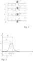
- Fig. 2 shows in a schematic phase representation a single dosing quantity 2 when approaching and passing through the measuring section of the capacitive sensor 17.
- a temporal course of a measuring signal S is recorded by means of the capacitive measuring device 6 and its capacitive sensor 17 as part of it when the dosing quantity 2 passes through, which is shown in the form of a schematic diagram in Fig. 3
- a ejection time t a is entered, at which the ejection of the dosing quantity 2 in the ejection position III after Fig. 1 is carried out.
- this is the time at which the control unit 18 gives the signal to apply the discharge overpressure p to the metering opening 7 in the discharge position III.
- the dosing quantity 2 is located directly at the upper input of the capacitive sensor 17 at a first time t 1 and does not yet generate a measuring signal S.
- the size of the measuring signal S is still approximately zero at time t 1.
- the dosing quantity 2 is located in the input section of the measuring section of the capacitive sensor 17 at a second time t 2 , with the course of the measuring signal S increasing, and at the fourth time t 4 in the output section of the measuring section of the capacitive sensor 17, with the course of the measuring signal S decreasing.
- dosing quantity 2' generates a peak value or a maximum value S p of the measuring signal S, from which an associated maximum value time t p is determined as the third time according to the diagram after Fig. 3 is determined.
- the time difference between the discharge time t a and the maximum value time t p is now calculated and used as the actual time period ⁇ t for the duration until the maximum value S p is reached.
- this actual time period ⁇ t is compared with at least one target time period.
- a target time period can be a single, fixed target time period.
- a tolerance range was defined.
- an upper limit time span ⁇ t o from the discharge time t a to the upper limit time t o was set as a first target time span.
- a lower limit time span ⁇ t u from the discharge time t a to the lower limit time t u was set as a second target time span.
- the upper limit time span ⁇ t o and the lower limit time span ⁇ t u define a tolerance range for the actual time span ⁇ t. If the actual time span ⁇ t is within this tolerance range, i.e. if the maximum value time t p is as shown in Fig. 3 between the upper limit time t o and the lower limit time t u , then the above in connection with Fig. 1 described dosing process remains unaffected.
- the discharge overpressure p is increased according to the method according to the invention.
- the discharge overpressure p is increased in such a way that or until the actual time span ⁇ t is again in the tolerance range described above.
- the discharge overpressure p is also adjusted in the opposite direction: If the time span comparison shows that the actual time span ⁇ t falls below the lower limit time span ⁇ t u , i.e. that the maximum value time t p is below the lower limit time t u , then this is a sign that the blow-out and fall speed of the dosing quantity 2 is too high. As a consequence and To compensate, the method according to the invention reduces the discharge overpressure p. The reduction in the discharge overpressure p occurs in such a way that or until the actual time period ⁇ t is again in the tolerance range described above.
- the invention is about keeping the measured actual time period ⁇ t as constant as possible, or at least within a predetermined tolerance range. If an adjustment of the discharge overpressure p is required for this purpose, this adjustment (increase or decrease) can be carried out incrementally in fixed pressure steps. Alternatively, the method according to the invention provides for an adjustment proportional to the deviation of the actual time period ⁇ t from the target time value.
- the adjustment can be carried out using random individual time measurements.
- the actual time period ⁇ t is formed by an average of several recorded differences between a measurement reference time and the emission reference time t a , with this average then being compared with the at least one target time period.
- the comparison result can be displayed to the operating personnel so that they can make a manual adjustment of the discharge overpressure p.
- the discharge overpressure p is adjusted automatically by means of the control unit 18, into which the measurement data of the capacitive measuring device 6 are fed, whereby an automatic control loop is then formed.
Landscapes
- Engineering & Computer Science (AREA)
- Mechanical Engineering (AREA)
- Health & Medical Sciences (AREA)
- Quality & Reliability (AREA)
- Animal Behavior & Ethology (AREA)
- Medicinal Chemistry (AREA)
- Pharmacology & Pharmacy (AREA)
- Life Sciences & Earth Sciences (AREA)
- Chemical & Material Sciences (AREA)
- General Health & Medical Sciences (AREA)
- Public Health (AREA)
- Veterinary Medicine (AREA)
- Physics & Mathematics (AREA)
- Fluid Mechanics (AREA)
- General Physics & Mathematics (AREA)
- Basic Packing Technique (AREA)
- Filling Or Emptying Of Bunkers, Hoppers, And Tanks (AREA)
Priority Applications (4)
| Application Number | Priority Date | Filing Date | Title |
|---|---|---|---|
| EP23191975.4A EP4509802A1 (fr) | 2023-08-17 | 2023-08-17 | Procédé de production de quantités dosées individuelles à l'aide d'un cylindre de dosage |
| US18/795,918 US12617565B2 (en) | 2023-08-17 | 2024-08-06 | Method for producing individual dosing quantities via a drum dosing device |
| CA3251680A CA3251680A1 (en) | 2023-08-17 | 2024-08-12 | Method for producing individual dosing quantities by means of a drum dosing device |
| CN202411119494.5A CN119488434A (zh) | 2023-08-17 | 2024-08-15 | 用于借助于辊式配给器产生单个配给量的方法 |
Applications Claiming Priority (1)
| Application Number | Priority Date | Filing Date | Title |
|---|---|---|---|
| EP23191975.4A EP4509802A1 (fr) | 2023-08-17 | 2023-08-17 | Procédé de production de quantités dosées individuelles à l'aide d'un cylindre de dosage |
Publications (1)
| Publication Number | Publication Date |
|---|---|
| EP4509802A1 true EP4509802A1 (fr) | 2025-02-19 |
Family
ID=87696070
Family Applications (1)
| Application Number | Title | Priority Date | Filing Date |
|---|---|---|---|
| EP23191975.4A Pending EP4509802A1 (fr) | 2023-08-17 | 2023-08-17 | Procédé de production de quantités dosées individuelles à l'aide d'un cylindre de dosage |
Country Status (3)
| Country | Link |
|---|---|
| EP (1) | EP4509802A1 (fr) |
| CN (1) | CN119488434A (fr) |
| CA (1) | CA3251680A1 (fr) |
Citations (4)
| Publication number | Priority date | Publication date | Assignee | Title |
|---|---|---|---|---|
| DE10226989A1 (de) * | 2002-06-18 | 2004-01-08 | Harro Höfliger Verpackungsmaschinen GmbH | Verfahren zum Abfüllen von mikronisierten Pulvern in Kleinstmengen und Vorrichtung zum Durchführen dieses Verfahrens |
| DE102014200484A1 (de) * | 2014-01-14 | 2015-07-16 | Robert Bosch Gmbh | Vorrichtung zum Dosieren von feinkörnigem Füllgut in Verpackungsbehälter |
| EP3608233A1 (fr) * | 2018-08-08 | 2020-02-12 | Harro Höfliger Verpackungsmaschinen GmbH | Cylindre doseur |
| EP3608232A1 (fr) | 2018-08-08 | 2020-02-12 | Harro Höfliger Verpackungsmaschinen GmbH | Procédé de production de quantités de dosage individuelles au moyen d'un doseur à rouleaux |
-
2023
- 2023-08-17 EP EP23191975.4A patent/EP4509802A1/fr active Pending
-
2024
- 2024-08-12 CA CA3251680A patent/CA3251680A1/en active Pending
- 2024-08-15 CN CN202411119494.5A patent/CN119488434A/zh active Pending
Patent Citations (4)
| Publication number | Priority date | Publication date | Assignee | Title |
|---|---|---|---|---|
| DE10226989A1 (de) * | 2002-06-18 | 2004-01-08 | Harro Höfliger Verpackungsmaschinen GmbH | Verfahren zum Abfüllen von mikronisierten Pulvern in Kleinstmengen und Vorrichtung zum Durchführen dieses Verfahrens |
| DE102014200484A1 (de) * | 2014-01-14 | 2015-07-16 | Robert Bosch Gmbh | Vorrichtung zum Dosieren von feinkörnigem Füllgut in Verpackungsbehälter |
| EP3608233A1 (fr) * | 2018-08-08 | 2020-02-12 | Harro Höfliger Verpackungsmaschinen GmbH | Cylindre doseur |
| EP3608232A1 (fr) | 2018-08-08 | 2020-02-12 | Harro Höfliger Verpackungsmaschinen GmbH | Procédé de production de quantités de dosage individuelles au moyen d'un doseur à rouleaux |
Also Published As
| Publication number | Publication date |
|---|---|
| CA3251680A1 (en) | 2025-06-04 |
| CN119488434A (zh) | 2025-02-21 |
| US20250058910A1 (en) | 2025-02-20 |
Similar Documents
| Publication | Publication Date | Title |
|---|---|---|
| EP3608232B1 (fr) | Procédé de production de quantités de dosage individuelles au moyen d'un doseur à rouleaux | |
| EP2168761B1 (fr) | Procédé de surveillance de la qualité de matériaux de compression en poudre et une presse rotative destinée à l'exécution du procédé | |
| DE2447395B2 (de) | Verteileinrichtung für Flüssigkeiten, insbesondere in der Landwirtschaft | |
| EP2707138A2 (fr) | Dispositif et procédé pour broyer des particules dans un matériau coulant | |
| EP1693182A2 (fr) | Procédé et dispositif pour le pressage d'essai de comprimés multi-couches ou de comprimés enrobés | |
| EP4044787A1 (fr) | Machine de distribution agricole | |
| EP4208003B1 (fr) | Procede et dispositif permettant d'adapter le fonctionnement d'un dispositif de singulation et le fonctionnement d'un dispositif de portionnement | |
| EP3238930A1 (fr) | Presse rotative et procédé d'installation et/ou de fonctionnement d'une presse rotative | |
| DE2443551A1 (de) | Verfahren und anordnung zum herstellen von zigaretten mit verstaerkten enden | |
| EP4509802A1 (fr) | Procédé de production de quantités dosées individuelles à l'aide d'un cylindre de dosage | |
| EP3926308B1 (fr) | Procédé de fonctionnement d'un dispositif de mélange d'une installation | |
| EP3326440B1 (fr) | Procédé de détermination de paramètres d'étalonnage d'une machine de distribution agricole | |
| EP3064191B1 (fr) | Procede de fonctionnement d'une machine de remplissage de capsules | |
| DE102010003814B4 (de) | Verfahren zur automatischen Dosierung und Dosiervorrichtung | |
| DE102015210212A1 (de) | Verfahren und Vorrichtung zum Ausbringen von körnigem Gut | |
| DE102005030311B3 (de) | Verfahren zur Pressung von Tabletten und Rundläufer- Tablettiermaschine | |
| EP1135293B1 (fr) | Procede et dispositif pour remplir des futs | |
| DE4106637C2 (fr) | ||
| EP1810819B1 (fr) | Presse rotative et procédé destinés à la surveillance de la production de tablettes dans une presse rotative | |
| EP4598721B1 (fr) | Procédé de production de composants à partir de polyuréthane dans une méthode de tir | |
| EP3100604A1 (fr) | Procede de reglage d'une unite de dosage de produit a epandre sous forme de granules et unite de dosage associee | |
| EP3928971B1 (fr) | Procédé de suivi des produits dans une installation | |
| DE102023125660B3 (de) | Verfahren zur Versuchspressung von Presslingen in einer Rundläuferpresse | |
| EP4044788B1 (fr) | Procédé permettant de faire fonctionner un dispositif de création de portions | |
| EP4105615B1 (fr) | Procédé de dosage pour unités posologiques et utilisation d'une vanne doseuse dans un dispositif d'étalonnage pour un système de mesure capacitif |
Legal Events
| Date | Code | Title | Description |
|---|---|---|---|
| PUAI | Public reference made under article 153(3) epc to a published international application that has entered the european phase |
Free format text: ORIGINAL CODE: 0009012 |
|
| STAA | Information on the status of an ep patent application or granted ep patent |
Free format text: STATUS: THE APPLICATION HAS BEEN PUBLISHED |
|
| AK | Designated contracting states |
Kind code of ref document: A1 Designated state(s): AL AT BE BG CH CY CZ DE DK EE ES FI FR GB GR HR HU IE IS IT LI LT LU LV MC ME MK MT NL NO PL PT RO RS SE SI SK SM TR |
|
| STAA | Information on the status of an ep patent application or granted ep patent |
Free format text: STATUS: REQUEST FOR EXAMINATION WAS MADE |
|
| 17P | Request for examination filed |
Effective date: 20250819 |