EP4509824A2 - Röntgenstrahlerzeugungsröhre, röntgenstrahlerzeugungsvorrichtung und röntgenbildgebungsvorrichtung - Google Patents
Röntgenstrahlerzeugungsröhre, röntgenstrahlerzeugungsvorrichtung und röntgenbildgebungsvorrichtung Download PDFInfo
- Publication number
- EP4509824A2 EP4509824A2 EP24223612.3A EP24223612A EP4509824A2 EP 4509824 A2 EP4509824 A2 EP 4509824A2 EP 24223612 A EP24223612 A EP 24223612A EP 4509824 A2 EP4509824 A2 EP 4509824A2
- Authority
- EP
- European Patent Office
- Prior art keywords
- ray generating
- insulating tube
- ray
- tube
- tubular
- Prior art date
- Legal status (The legal status is an assumption and is not a legal conclusion. Google has not performed a legal analysis and makes no representation as to the accuracy of the status listed.)
- Pending
Links
Images


Classifications
-
- H—ELECTRICITY
- H01—ELECTRIC ELEMENTS
- H01J—ELECTRIC DISCHARGE TUBES OR DISCHARGE LAMPS
- H01J35/00—X-ray tubes
- H01J35/02—Details
- H01J35/16—Vessels; Containers; Shields associated therewith
- H01J35/165—Vessels; Containers; Shields associated therewith joining connectors to the tube
-
- H—ELECTRICITY
- H01—ELECTRIC ELEMENTS
- H01J—ELECTRIC DISCHARGE TUBES OR DISCHARGE LAMPS
- H01J35/00—X-ray tubes
- H01J35/02—Details
- H01J35/16—Vessels; Containers; Shields associated therewith
-
- G—PHYSICS
- G01—MEASURING; TESTING
- G01N—INVESTIGATING OR ANALYSING MATERIALS BY DETERMINING THEIR CHEMICAL OR PHYSICAL PROPERTIES
- G01N23/00—Investigating or analysing materials by the use of wave or particle radiation, e.g. X-rays or neutrons, not covered by groups G01N3/00 – G01N17/00, G01N21/00 or G01N22/00
- G01N23/02—Investigating or analysing materials by the use of wave or particle radiation, e.g. X-rays or neutrons, not covered by groups G01N3/00 – G01N17/00, G01N21/00 or G01N22/00 by transmitting the radiation through the material
- G01N23/04—Investigating or analysing materials by the use of wave or particle radiation, e.g. X-rays or neutrons, not covered by groups G01N3/00 – G01N17/00, G01N21/00 or G01N22/00 by transmitting the radiation through the material and forming images of the material
-
- H—ELECTRICITY
- H01—ELECTRIC ELEMENTS
- H01J—ELECTRIC DISCHARGE TUBES OR DISCHARGE LAMPS
- H01J35/00—X-ray tubes
- H01J35/02—Details
- H01J35/04—Electrodes ; Mutual position thereof; Constructional adaptations therefor
- H01J35/06—Cathodes
-
- H—ELECTRICITY
- H01—ELECTRIC ELEMENTS
- H01J—ELECTRIC DISCHARGE TUBES OR DISCHARGE LAMPS
- H01J35/00—X-ray tubes
- H01J35/02—Details
- H01J35/04—Electrodes ; Mutual position thereof; Constructional adaptations therefor
- H01J35/08—Anodes; Anti cathodes
-
- H—ELECTRICITY
- H01—ELECTRIC ELEMENTS
- H01J—ELECTRIC DISCHARGE TUBES OR DISCHARGE LAMPS
- H01J35/00—X-ray tubes
- H01J35/32—Tubes wherein the X-rays are produced at or near the end of the tube or a part thereof which tube or part has a small cross-section to facilitate introduction into a small hole or cavity
-
- H—ELECTRICITY
- H05—ELECTRIC TECHNIQUES NOT OTHERWISE PROVIDED FOR
- H05G—X-RAY TECHNIQUE
- H05G1/00—X-ray apparatus involving X-ray tubes; Circuits therefor
- H05G1/02—Constructional details
- H05G1/04—Mounting the X-ray tube within a closed housing
- H05G1/06—X-ray tube and at least part of the power supply apparatus being mounted within the same housing
-
- H—ELECTRICITY
- H01—ELECTRIC ELEMENTS
- H01J—ELECTRIC DISCHARGE TUBES OR DISCHARGE LAMPS
- H01J35/00—X-ray tubes
- H01J35/02—Details
- H01J35/04—Electrodes ; Mutual position thereof; Constructional adaptations therefor
- H01J35/08—Anodes; Anti cathodes
- H01J35/112—Non-rotating anodes
- H01J35/116—Transmissive anodes
Definitions
- the present invention relates to an X-ray generating tube, an X-ray generating apparatus, and an X-ray imaging apparatus.
- PTL 1 discloses an X-ray generating tube including an insulating tube, a cathode, an anode, and an inner anode layer.
- the insulating tube, the cathode, and the anode constitute an envelope that defines an inner space, and the inner anode layer extends from the anode along the inner surface of the insulating tube.
- the inner anode layer is electrically connected to the anode and suppresses charge of the insulating tube.
- the thin insulating tube may weaken the insulating tube or the X-ray generating tube. Further, the thin insulating tube may decrease the withstand voltage of the insulating tube. At the distal end (end on the cathode side) of the inner anode layer where the field strength readily increases, discharge may occur in a direction passing through the insulating tube to cause leakage via a through hole formed by the discharge.
- the present invention has as its object to provide a technique advantageous for lightening an X-ray generating tube while suppressing discharge passing through an insulating tube and ensuring the strength of the insulating tube.
- an X-ray generating tube comprising an insulating tube having a first open end and a second open end, a cathode including an electron emission source and arranged to close the first open end of the insulating tube, an anode including a target that generates an X-ray upon collision with an electron from the electron emission source and arranged to close the second open end of the insulating tube, and a tubular electrical conductive member extending from the anode in an inner space of the insulating tube, wherein the insulating tube includes a tubular rib at a position spaced apart from the first open end and spaced apart from the second open end, and the tubular rib is arranged in a radial direction when viewed from an end of the tubular electrical conductive member on a side of the cathode.
- an X-ray generating tube comprising an insulating tube having a first open end and a second open end, a cathode including an electron emission source and arranged to close the first open end of the insulating tube, an anode including a target that generates an X-ray upon collision with an electron from the electron emission source and arranged to close the second open end of the insulating tube, a tubular electrical conductive member extending from the anode in an inner space of the insulating tube, and a covering member arranged to cover an outside of the insulating tube, having a sheet resistance value smaller than a sheet resistance value of the insulating tube, and configured to receive a potential, wherein the insulating tube includes a tubular rib arranged in a radial direction when viewed from an end of the tubular electrical conductive member on a side of the cathode.
- an X-ray generating apparatus comprising an X-ray generating tube according to the first or second aspect, and a driving circuit configured to drive the X-ray generating tube.
- an X-ray generating apparatus configured to generate an X-ray having passed through an object after radiated from the X-ray generating apparatus.
- the present invention provides a technique advantageous for lightening an X-ray generating tube while suppressing discharge passing through an insulating tube and ensuring the strength of the insulating tube.
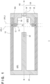
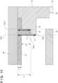
- Fig. 1 schematically shows the arrangement of an X-ray generating tube 1 according to a first embodiment of the present invention.
- the X-ray generating tube 1 according to the first embodiment can include an insulating tube 10, a cathode 20, an anode 30, and a tubular electrical conductive member 50.
- the insulating tube 10 has a first open end OP1 and a second open end OP2.
- the insulating tube 10 is made of an insulating material (for example, ceramic or glass) and has a tubular shape extending in an axial direction AD.
- the tubular shape is a shape that forms a closed figure on a section perpendicular to the axial direction AD and is, for example, a cylindrical shape.
- the concept of the tubular shape can include a shape having different sectional areas at different positions in the axial direction AD.
- the cathode 20 is arranged to close the first open end OP1 of the insulating tube 10.
- the cathode 20 includes an electron emission source 22 configured to emit electrons.
- the electron emission source 22 can include, for example, a filament, a converging electrode configured to cause electrons emitted from the filament to converge, and the like.
- a potential of -100 kV with reference to the anode 30 can be applied to the cathode 20.
- the anode 30 is arranged to close the second open end OP2 of the insulating tube 10.
- the anode 30 can include a target 34, a target holding plate 33 that holds the target 34, and an electrode 32 that holds the target holding plate 33.
- the electrode 32 is electrically connected to the target 34 and applies a potential to the target 34. Electrons from the electron emission source 22 collide with the target 34 and the target 34 generates an X-ray. The generated X-ray passes through the target holding plate 33 and is radiated outside the X-ray generating tube 1.
- the anode 30 can be maintained at, for example, the ground potential but may be maintained at another potential.
- the target 34 can be formed from a material of high melting point and high X-ray generation efficiency such as tungsten, tantalum, or molybdenum.
- the target holding plate 33 can be formed from, for example, a material that transmits an X-ray, such as beryllium or diamond.
- the tubular electrical conductive member 50 is arranged to extend from the anode 30 in the inner space of the insulating tube 10.
- the tubular electrical conductive member 50 has a tubular shape extending in the axial direction AD.
- the tubular electrical conductive member 50 is electrically connected to the anode 30.
- the tubular electrical conductive member 50 is spaced apart from the cathode 20.
- the tubular electrical conductive member 50 can be arranged to surround at least part of the orbit (path between the electron emission source 22 and the target 34) of electrons emitted from the electron emission source 22.
- the tubular electrical conductive member 50 can function to reduce the influence of charge of the insulating tube 10 on the orbit of electrons emitted from the electron emission source 22.
- the tubular electrical conductive member 50 can be arranged to, for example, contact the inner side surface of the insulating tube 10, but may be arranged apart from the inner side surface of the insulating tube 10.
- the tubular electrical conductive member 50 may be constituted integrally with the anode 30, but may be constituted separately from the anode 30 and coupled or fixed to the anode 30.
- the tubular electrical conductive member 50 can be, for example, a film formed on the inner side surface of the insulating tube 10 by vapor deposition such as CVD (Chemical Vapor Deposition) or PVD (Physical Vapor Deposition), plating, coating, or the like.
- CVD Chemical Vapor Deposition
- PVD Physical Vapor Deposition
- the insulating tube 10 can include a tubular rib 12 at a position spaced apart from the first open end OP1 and spaced apart from the second open end OP2.
- the thickness of a portion of the insulating tube 10 where the tubular rib 12 is arranged is larger than that of the remaining portion of the insulating tube 10.
- the tubular rib 12 increases the strength of the insulating tube 10.
- the tubular rib 12 is provided advantageously to decrease the thickness of a portion of the insulating tube 10 except the portion where the tubular rib 12 is arranged. This can contribute to lightening of the X-ray generating tube 1.
- the tubular rib 12 can be arranged to face the inner space of the insulating tube 10.
- the tubular rib 12 can be arranged in a radiation direction RD when viewed from an end 52 of the tubular electrical conductive member 50 on the cathode 20 side.
- the end 52 of the tubular electrical conductive member 50 is a portion where the field strength readily increases.
- the tubular rib 12 is advantageous for achieving both suppression of discharge passing through the insulating tube 10 and ensuring of the strength of the insulating tube 10.
- the end 52 of the tubular electrical conductive member 50 on the cathode 20 side can be positioned between a first virtual plane VPL1 including an end face of the tubular rib 12 on the cathode 20 side and a second virtual plane VPL2 including an end face of the tubular rib 12 on the anode 30 side.
- the first virtual plane VPL1 and an end face 51 of the tubular electrical conductive member 50 on the cathode 20 side are preferably spaced apart from each other in terms of improvement of the withstand voltage.
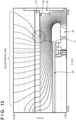
- Fig. 13 shows a simulation result representing a potential in the X-ray generating tube.
- the field strength is high at a portion where the interval between equipotential lines is small.
- the field strength at the end of the tubular electrical conductive member 50 is high and discharge passing through the insulating tube 10 readily occurs at this portion. To suppress the discharge, it is effective to provide the tubular rib 12 at this portion and thicken the insulating tube 10.
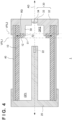
- Fig. 2 schematically shows the arrangement of an X-ray generating tube 1 according to a second embodiment of the present invention. Matters not mentioned in the second embodiment can comply with the first embodiment.
- the X-ray generating tube 1 according to the second embodiment is different from the X-ray generating tube 1 according to the first embodiment in that it includes a covering member 40 which is arranged to cover the outside of an insulating tube 10 and receives a potential.
- the covering member 40 can be arranged to be electrically connected to a cathode 20 and an anode 30.
- the covering member 40 can cover the cathode 20, the insulating tube 10, and the anode 30 so as to, for example, contact the cathode 20 and the anode 30.
- the sheet resistance value of the covering member 40 is smaller than that of the insulating tube 10.
- the sheet resistance value of the insulating tube 10 at 100°C is R s 1
- the sheet resistance value of the covering member 40 at 100°C is R s 2.
- R s 2/R s 1 is preferably equal to or higher than 1 ⁇ 10 -5 and equal to or lower than 1 ⁇ 10 -1 .
- the covering member 40 can be formed from, for example, a glassy material such as Kovar glass, glaze, or frit glass, or a metal oxide film.
- the covering member 40 covers the insulating tube 10 advantageously to, for example, form a smooth surface on the outside of the insulating tube 10 and suppress entrance of dirt between particles constituting the insulating tube 10. This can improve a creepage withstand voltage on the outer surface of the insulating tube 10.
- the covering member 40 has low conductivity, and even if charge occurs on the outer surface of the insulating tube 10, charges can be moved before generating a large potential difference. Generation of discharge that may damage the insulating tube 10 can be prevented.
- the covering of the insulating tube 10 with the covering member 40 may increase the field strength at the end of a tubular electrical conductive member 50, as shown in Fig. 14.
- Fig. 14 shows a simulation result representing a potential in the X-ray generating tube in which the insulating tube 10 is covered with the covering member 40.
- the field strength (interval between equipotential lines) on the surface of the covering member 40 is uniformed by providing the covering member 40.
- this further increases the field strength at the end of the tubular electrical conductive member 50 near the end of the tubular electrical conductive member 50, as indicated by a symbol A.
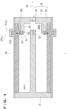
- Fig. 3 schematically shows the arrangement of an X-ray generating tube 1 according to a third embodiment of the present invention. Matters not mentioned in the third embodiment can comply with the first or second embodiment.
- a covering member 40 covering an insulating tube 10 is provided in all the following embodiments, the covering member 40 is not an essential constituent in the present invention.
- the covering member 40 is arranged to be electrically connected to a cathode 20 and an anode 30, but is arranged not to cover the side surfaces of the cathode 20 and anode 30.
- Fig. 4 schematically shows the arrangement of an X-ray generating tube 1 according to a fourth embodiment of the present invention. Matters not mentioned in the fourth embodiment can comply with the first or second embodiment.
- a covering member 40 is arranged to be electrically connected to a cathode 20 and an anode 30, but is arranged not to cover the side surfaces of the cathode 20 and anode 30.
- the cathode 20 has a portion covering part of the side surface of the covering member 40
- the anode 30 has a portion covering part of the side surface of the covering member 40.
- Fig. 5 schematically shows the arrangement of an X-ray generating tube 1 according to a fifth embodiment of the present invention. Matters not mentioned in the fifth embodiment can comply with the first to fourth embodiments.
- a tubular electrical conductive member 50 is arranged to surround an end of an electron emission source 22 on an anode 30 side.
- Fig. 5 shows an example in which the arrangement in which the tubular electrical conductive member 50 is arranged to surround the end of the electron emission source 22 on the anode 30 side is applied to the X-ray generating tube 1 according to the second embodiment. This arrangement is applicable to even the X-ray generating tubes 1 according to the first, third, and fourth embodiments.
- Fig. 6 schematically shows the arrangement of an X-ray generating tube 1 according to a sixth embodiment of the present invention. Matters not mentioned in the sixth embodiment can comply with the first to fifth embodiments.
- a tubular electrical conductive member 50 is arranged to form a space between the outer surface of the tubular electrical conductive member 50 and the inner surface of an insulating tube 10. This arrangement is applicable to even the X-ray generating tubes 1 according to the first to fifth embodiments.
- Fig. 7 schematically shows the arrangement of an X-ray generating tube 1 according to a seventh embodiment of the present invention. Matters not mentioned in the seventh embodiment can comply with the first to sixth embodiments.
- an end face 51 of a tubular electrical conductive member 50 on a cathode 20 side belongs to a first virtual plane VPL1 including an end face of a tubular rib 12 on the cathode 20 side. This arrangement is applicable to even the X-ray generating tubes 1 according to the first and third to fifth embodiments.
- Fig. 8 schematically shows the arrangement of an X-ray generating tube 1 according to an eighth embodiment of the present invention. Matters not mentioned in the eighth embodiment can comply with the first to seventh embodiments.
- a tubular rib 12 is arranged to project toward the outer space of an insulating tube 10. This arrangement is applicable to even the X-ray generating tubes 1 according to the first and third to seventh embodiments.
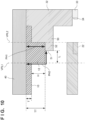
- Fig. 9 schematically shows the arrangement of an X-ray generating tube 1 according to a ninth embodiment of the present invention. Matters not mentioned in the ninth embodiment can comply with the first to seventh embodiments.
- a tubular rib 12 includes an inner tubular rib 121 arranged to face the inner space of an insulating tube 10 and an outer tubular rib 122 arranged to project toward the outer space of the insulating tube 10. This arrangement is applicable to even the X-ray generating tubes 1 according to the first and third to seventh embodiments.
- T is the thickness of a portion of the insulating tube 10 that does not have the tubular rib
- H is the thickness of the tubular rib
- TT is the thickness of a portion of the insulating tube 10 that has the tubular rib 12.
- L is the distance between the first virtual plane VPL1 and the end face 51 of the tubular electrical conductive member 50 on the cathode 20 side.
- the creepage withstand voltage of an insulator is lower than the bulk withstand voltage, and the creepage withstand voltage is experimentally known to be 1/3 to 1/10 times.
- E1 (kV/mm) is the bulk withstand voltage of an insulator forming the insulating tube 10
- E2 (kV/mm) is the creepage withstand voltage of the insulator.
- a withstand voltage (withstand voltage on a path PH1) in the direction of thickness of the portion of the insulating tube 10 that has the tubular rib 12 is E1 ⁇ TT (kV).
- a withstand voltage (withstand voltage on a path PH2) via the creepage surface of the tubular rib 12 is E2 ⁇ (L + H) + E1 ⁇ T.
- the withstand voltage (withstand voltage on the path PH2) via the creepage surface of the tubular rib 12 is E2 ⁇ H + E1 ⁇ T.
- the arrangement in Fig. 10 is superior in the withstand voltage via the creepage surface to the arrangement in Fig. 11 .
- an insulating tube 10 includes a tubular rib 12 arranged in the radial direction when viewed from an end of a tubular electrical conductive member 50 on a cathode 20 side.
- An end 52 of the tubular electrical conductive member 50 on the cathode 20 side can be positioned between a first virtual plane VPL1 including an end face of the tubular rib 12 on the cathode 20 side and a second virtual plane VPL2 including an end face of the tubular rib 12 on an anode 30 side.
- the second virtual plane VPL2 can form an end face of the insulating tube 10 on the anode 30 side.
- the end face of the tubular rib 12 on the anode 30 side can belong to the same plane as that of the end face of the insulating tube 10 on the anode 30 side.
- the tubular rib 12 can be arranged in contact with the anode 30.
- the X-ray generating tube 1 according to the 10th embodiment can include a covering member 40 that is arranged to cover the outside of the insulating tube 10 and receives a potential.
- the covering member 40 can be arranged to be electrically connected to the cathode 20 and the anode 30.
- the covering member 40 can cover the cathode 20, the insulating tube 10, and the anode 30 so as to, for example, contact the cathode 20 and the anode 30.
- the sheet resistance value of the covering member 40 is smaller than that of the insulating tube 10.
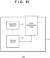
- Fig. 15 shows the arrangement of an X-ray generating apparatus 100 according to an embodiment of the present invention.
- the X-ray generating apparatus 100 can include an X-ray generating tube 1 and a driving circuit 3 that drives the X-ray generating tube 1.
- the X-ray generating apparatus 100 can further include a booster circuit 2 that applies a boosted voltage to the driving circuit 3.
- the X-ray generating apparatus 100 can further include a container 4 that contains the X-ray generating tube 1, the driving circuit 3, and the booster circuit 2.
- the container 4 can be filled with insulating oil.
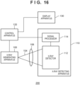
- Fig. 16 shows the arrangement of an X-ray imaging apparatus 200 according to an embodiment of the present invention.
- the X-ray imaging apparatus 200 can include an X-ray generating apparatus 100, and an X-ray detecting apparatus 110 that detects an X-ray 104 having passed through an object 106 after radiated from the X-ray generating apparatus 100.
- the X-ray imaging apparatus 200 may further include a control apparatus 120 and a display apparatus 130.
- the X-ray detecting apparatus 110 can include an X-ray detector 112 and a signal processor 114.
- the control apparatus 120 can control the X-ray generating apparatus 100 and the X-ray detecting apparatus 110.
- the X-ray detector 112 detects or images the X-ray 104 having passed through the object 106 after radiated from the X-ray generating apparatus 100.
- the signal processor 114 can process a signal output from the X-ray detector 112 and supply the processed signal to the control apparatus 120.
- the control apparatus 120 causes the display apparatus 130 to display an image based on the signal supplied from the signal processor 114.
- Item 1 An X-ray generating tube characterized by comprising:
- Item 2 The X-ray generating tube according to item 1, characterized in that the end of the tubular electrical conductive member on the side of the cathode is positioned between a first virtual plane including an end face of the tubular rib on the side of the cathode and a second virtual plane including an end face of the tubular rib on a side of the anode.
- Item 3 The X-ray generating tube according to item 1, characterized in that the end face of the tubular electrical conductive member on the side of the cathode belongs to a first virtual plane including an end face of the tubular rib on the side of the cathode.
- Item 4 The X-ray generating tube according to any one of items 1 to 3, characterized in that the tubular electrical conductive member is arranged to define a space between an outer surface of the tubular electrical conductive member and an inner surface of the insulating tube.
- Item 5 The X-ray generating tube according to any one of items 1 to 4, characterized in that the tubular rib is arranged to face the inner space.
- Item 6 The X-ray generating tube according to any one of items 1 to 4, characterized in that the tubular rib is arranged to project toward an outer space of the insulating tube.
- Item 7 The X-ray generating tube according to any one of items 1 to 4, characterized in that the tubular rib includes an inner tubular rib arranged to face the inner space and an outer tubular rib arranged to project toward an outer space of the insulating tube.
- Item 8 The X-ray generating tube according to any one of items 1 to 7, characterized by further comprising a covering member arranged to cover an outside of the insulating tube and configured to receive a potential, wherein a sheet resistance value of the covering member is smaller than a sheet resistance value of the insulating tube.
- Item 9 The X-ray generating tube according to item 8, characterized in that the covering member is electrically connected to the cathode and the anode.
- Item 10 The X-ray generating tube according to any one of items 1 to 9, characterized in that the tubular electrical conductive member is arranged to surround an end of the electron emission source on a side of the anode.
- An X-ray generating tube characterized by comprising:
- Item 12 The X-ray generating tube according to item 11, characterized in that the covering member is electrically connected to the cathode and the anode.
- Item 13 The X-ray generating tube according to item 11 or 12, characterized in that the end of the tubular electrical conductive member on the side of the cathode is positioned between a virtual plane including an end face of the tubular rib on the side of the cathode and a virtual plane including the second open end.
- Item 14 The X-ray generating tube according to any one of items 11 to 13, characterized in that the tubular electrical conductive member is arranged to surround an end of the electron emission source on a side of the anode.
- An X-ray generating apparatus characterized by comprising:
- An X-ray imaging apparatus characterized by comprising:
Landscapes
- Physics & Mathematics (AREA)
- Health & Medical Sciences (AREA)
- Life Sciences & Earth Sciences (AREA)
- Chemical & Material Sciences (AREA)
- Analytical Chemistry (AREA)
- Biochemistry (AREA)
- General Health & Medical Sciences (AREA)
- General Physics & Mathematics (AREA)
- Immunology (AREA)
- Pathology (AREA)
- X-Ray Techniques (AREA)
Priority Applications (1)
| Application Number | Priority Date | Filing Date | Title |
|---|---|---|---|
| EP24223612.3A EP4509824A3 (de) | 2018-12-28 | 2018-12-28 | Röntgenstrahlerzeugungsröhre, röntgenstrahlerzeugungsvorrichtung und röntgenbildgebungsvorrichtung |
Applications Claiming Priority (3)
| Application Number | Priority Date | Filing Date | Title |
|---|---|---|---|
| EP18944566.1A EP3905301B1 (de) | 2018-12-28 | 2018-12-28 | Röntgenstrahlröhre, röntgenstrahlenerzeugungsvorrichtung und röntgenstrahlenbildgebungsvorrichtung |
| PCT/JP2018/048607 WO2020136911A1 (ja) | 2018-12-28 | 2018-12-28 | X線発生管、x線発生装置およびx線撮像装置 |
| EP24223612.3A EP4509824A3 (de) | 2018-12-28 | 2018-12-28 | Röntgenstrahlerzeugungsröhre, röntgenstrahlerzeugungsvorrichtung und röntgenbildgebungsvorrichtung |
Related Parent Applications (2)
| Application Number | Title | Priority Date | Filing Date |
|---|---|---|---|
| EP18944566.1A Division-Into EP3905301B1 (de) | 2018-12-28 | 2018-12-28 | Röntgenstrahlröhre, röntgenstrahlenerzeugungsvorrichtung und röntgenstrahlenbildgebungsvorrichtung |
| EP18944566.1A Division EP3905301B1 (de) | 2018-12-28 | 2018-12-28 | Röntgenstrahlröhre, röntgenstrahlenerzeugungsvorrichtung und röntgenstrahlenbildgebungsvorrichtung |
Publications (2)
| Publication Number | Publication Date |
|---|---|
| EP4509824A2 true EP4509824A2 (de) | 2025-02-19 |
| EP4509824A3 EP4509824A3 (de) | 2026-03-11 |
Family
ID=68613345
Family Applications (2)
| Application Number | Title | Priority Date | Filing Date |
|---|---|---|---|
| EP24223612.3A Pending EP4509824A3 (de) | 2018-12-28 | 2018-12-28 | Röntgenstrahlerzeugungsröhre, röntgenstrahlerzeugungsvorrichtung und röntgenbildgebungsvorrichtung |
| EP18944566.1A Active EP3905301B1 (de) | 2018-12-28 | 2018-12-28 | Röntgenstrahlröhre, röntgenstrahlenerzeugungsvorrichtung und röntgenstrahlenbildgebungsvorrichtung |
Family Applications After (1)
| Application Number | Title | Priority Date | Filing Date |
|---|---|---|---|
| EP18944566.1A Active EP3905301B1 (de) | 2018-12-28 | 2018-12-28 | Röntgenstrahlröhre, röntgenstrahlenerzeugungsvorrichtung und röntgenstrahlenbildgebungsvorrichtung |
Country Status (7)
| Country | Link |
|---|---|
| US (1) | US10720299B1 (de) |
| EP (2) | EP4509824A3 (de) |
| JP (1) | JP6609088B1 (de) |
| KR (1) | KR102367142B1 (de) |
| CN (1) | CN113272931B (de) |
| TW (2) | TWI766217B (de) |
| WO (1) | WO2020136911A1 (de) |
Families Citing this family (6)
| Publication number | Priority date | Publication date | Assignee | Title |
|---|---|---|---|---|
| JP6609088B1 (ja) | 2018-12-28 | 2019-11-20 | キヤノンアネルバ株式会社 | X線発生管、x線発生装置およびx線撮像装置 |
| US11152184B2 (en) | 2019-08-06 | 2021-10-19 | Moxtek, Inc. | X-ray tube insulation, window, and focusing plate |
| JP6683903B1 (ja) * | 2019-09-03 | 2020-04-22 | キヤノンアネルバ株式会社 | X線発生装置およびx線撮像装置 |
| JP7486694B1 (ja) * | 2023-01-25 | 2024-05-17 | キヤノンアネルバ株式会社 | X線発生装置およびx線撮像装置 |
| JP7484032B1 (ja) * | 2023-01-25 | 2024-05-15 | キヤノンアネルバ株式会社 | X線発生装置およびx線撮像装置 |
| WO2025057338A1 (ja) * | 2023-09-13 | 2025-03-20 | キヤノンアネルバ株式会社 | X線発生装置およびx線撮像装置 |
Citations (2)
| Publication number | Priority date | Publication date | Assignee | Title |
|---|---|---|---|---|
| JP2016103451A (ja) | 2014-11-28 | 2016-06-02 | キヤノン株式会社 | X線発生管、x線発生装置およびx線撮影システム |
| EP3905301A1 (de) | 2018-12-28 | 2021-11-03 | Canon Anelva Corporation | Röntgenstrahlröhre, röntgenstrahlenerzeugungsvorrichtung und röntgenstrahlenbildgebungsvorrichtung |
Family Cites Families (14)
| Publication number | Priority date | Publication date | Assignee | Title |
|---|---|---|---|---|
| US2090636A (en) * | 1930-12-06 | 1937-08-24 | Dimitry E Olshevsky | X-ray tube |
| JPS58106745A (ja) * | 1981-12-18 | 1983-06-25 | Hitachi Ltd | 高電圧絶縁真空外囲器 |
| JP2766243B2 (ja) * | 1995-03-20 | 1998-06-18 | 日本電気株式会社 | 真空用絶縁スペーサ |
| DE19854199C1 (de) * | 1998-11-24 | 2000-03-30 | Siemens Ag | Röntgenbildverstärker mit Klebemontagetechnik und Verfahren zu dessen Herstellung |
| JP4435124B2 (ja) * | 2005-08-29 | 2010-03-17 | 株式会社東芝 | X線管 |
| JP5800578B2 (ja) | 2011-05-31 | 2015-10-28 | キヤノン株式会社 | X線管 |
| JP5804777B2 (ja) | 2011-06-01 | 2015-11-04 | キヤノン株式会社 | X線発生管及び、x線発生装置 |
| JP5921153B2 (ja) * | 2011-11-09 | 2016-05-24 | キヤノン株式会社 | 放射線発生管および放射線発生装置 |
| JP6049350B2 (ja) * | 2012-08-21 | 2016-12-21 | キヤノン株式会社 | 放射線発生管、放射線発生ユニット及び放射線撮影システム |
| JP2014086147A (ja) * | 2012-10-19 | 2014-05-12 | Canon Inc | 放射線発生管、放射線発生ユニット及び放射線撮影システム |
| JP6230389B2 (ja) * | 2013-06-05 | 2017-11-15 | キヤノン株式会社 | X線発生管及びそれを用いたx線発生装置とx線撮影システム |
| JP6327802B2 (ja) * | 2013-06-12 | 2018-05-23 | キヤノン株式会社 | 放射線発生管及びそれを用いた放射線発生装置と放射線撮影システム |
| JP6415250B2 (ja) * | 2014-10-29 | 2018-10-31 | キヤノン株式会社 | X線発生管、x線発生装置及びx線撮影システム |
| JP2017054679A (ja) * | 2015-09-09 | 2017-03-16 | 東芝電子管デバイス株式会社 | 固定陽極型x線管装置 |
-
2018
- 2018-12-28 JP JP2019532145A patent/JP6609088B1/ja active Active
- 2018-12-28 WO PCT/JP2018/048607 patent/WO2020136911A1/ja not_active Ceased
- 2018-12-28 KR KR1020217019801A patent/KR102367142B1/ko active Active
- 2018-12-28 CN CN201880100495.1A patent/CN113272931B/zh active Active
- 2018-12-28 EP EP24223612.3A patent/EP4509824A3/de active Pending
- 2018-12-28 EP EP18944566.1A patent/EP3905301B1/de active Active
-
2019
- 2019-06-24 US US16/449,968 patent/US10720299B1/en active Active
- 2019-12-20 TW TW108146834A patent/TWI766217B/zh active
- 2019-12-20 TW TW110124726A patent/TWI766748B/zh active
Patent Citations (2)
| Publication number | Priority date | Publication date | Assignee | Title |
|---|---|---|---|---|
| JP2016103451A (ja) | 2014-11-28 | 2016-06-02 | キヤノン株式会社 | X線発生管、x線発生装置およびx線撮影システム |
| EP3905301A1 (de) | 2018-12-28 | 2021-11-03 | Canon Anelva Corporation | Röntgenstrahlröhre, röntgenstrahlenerzeugungsvorrichtung und röntgenstrahlenbildgebungsvorrichtung |
Also Published As
| Publication number | Publication date |
|---|---|
| TW202032608A (zh) | 2020-09-01 |
| TW202139230A (zh) | 2021-10-16 |
| KR20210087102A (ko) | 2021-07-09 |
| EP3905301B1 (de) | 2025-02-12 |
| EP3905301A4 (de) | 2022-04-06 |
| US20200211808A1 (en) | 2020-07-02 |
| US10720299B1 (en) | 2020-07-21 |
| CN113272931A (zh) | 2021-08-17 |
| EP3905301A1 (de) | 2021-11-03 |
| CN113272931B (zh) | 2022-10-18 |
| EP3905301C0 (de) | 2025-02-12 |
| EP4509824A3 (de) | 2026-03-11 |
| KR102367142B1 (ko) | 2022-02-23 |
| TWI766217B (zh) | 2022-06-01 |
| TWI766748B (zh) | 2022-06-01 |
| JPWO2020136911A1 (ja) | 2021-02-18 |
| JP6609088B1 (ja) | 2019-11-20 |
| WO2020136911A1 (ja) | 2020-07-02 |
Similar Documents
| Publication | Publication Date | Title |
|---|---|---|
| EP3905301B1 (de) | Röntgenstrahlröhre, röntgenstrahlenerzeugungsvorrichtung und röntgenstrahlenbildgebungsvorrichtung | |
| US8837680B2 (en) | Radiation transmission type target | |
| US1211092A (en) | X-ray tube. | |
| KR20140066734A (ko) | 타겟 구조체 및 x선 발생장치 | |
| JP2012248505A (ja) | X線管 | |
| US9514910B2 (en) | Radiation tube, radiation generating apparatus, and radiation imaging system | |
| EP0009946A1 (de) | Röntgenröhre | |
| WO2008156361A2 (en) | Miniature x-ray source with guiding means for electrons and / or ions | |
| US11875965B2 (en) | X-ray tube | |
| EP2697814B1 (de) | Metallisierte keramik-abschlussplatte für einer röntgenröhre | |
| US3688146A (en) | Image amplifier having external electrostatic shield | |
| KR20160102748A (ko) | 전계 방출 엑스선 소스 장치 | |
| US12230468B2 (en) | X-ray system with field emitters and arc protection | |
| US20240021401A1 (en) | X-ray tube | |
| CN217444331U (zh) | 冷阴极x射线管及x射线发生装置 | |
| CN118571731A (zh) | 一种微焦点x射线管 | |
| JP4414114B2 (ja) | 蛍光表示管及びその駆動方法並びに駆動回路 | |
| EP4030459A1 (de) | Röntgenröhre | |
| US11955325B1 (en) | Electron multiplier and photoelectron multiplier including same | |
| US6147446A (en) | Image converter tube with means of prevention for stray glimmer | |
| AU763548B2 (en) | High energy X-ray tube | |
| US12125661B2 (en) | X-ray tube | |
| US1261708A (en) | Electron-discharge device. | |
| SU319007A1 (ru) | Электроннолучевая трубка для электростатической печати | |
| KR20220148725A (ko) | 엑스선 튜브 |
Legal Events
| Date | Code | Title | Description |
|---|---|---|---|
| PUAI | Public reference made under article 153(3) epc to a published international application that has entered the european phase |
Free format text: ORIGINAL CODE: 0009012 |
|
| STAA | Information on the status of an ep patent application or granted ep patent |
Free format text: STATUS: REQUEST FOR EXAMINATION WAS MADE |
|
| 17P | Request for examination filed |
Effective date: 20241230 |
|
| AC | Divisional application: reference to earlier application |
Ref document number: 3905301 Country of ref document: EP Kind code of ref document: P |
|
| AK | Designated contracting states |
Kind code of ref document: A2 Designated state(s): AL AT BE BG CH CY CZ DE DK EE ES FI FR GB GR HR HU IE IS IT LI LT LU LV MC MK MT NL NO PL PT RO RS SE SI SK SM TR |
|
| REG | Reference to a national code |
Ref country code: DE Ref legal event code: R079 Free format text: PREVIOUS MAIN CLASS: G01N0023040000 Ipc: H01J0035160000 |
|
| RIC1 | Information provided on ipc code assigned before grant |
Ipc: G01N 23/04 20180101ALI20250403BHEP Ipc: H01J 35/08 20060101ALI20250403BHEP Ipc: H01J 35/16 20060101AFI20250403BHEP |
|
| PUAL | Search report despatched |
Free format text: ORIGINAL CODE: 0009013 |
|
| AK | Designated contracting states |
Kind code of ref document: A3 Designated state(s): AL AT BE BG CH CY CZ DE DK EE ES FI FR GB GR HR HU IE IS IT LI LT LU LV MC MK MT NL NO PL PT RO RS SE SI SK SM TR |
|
| RIC1 | Information provided on ipc code assigned before grant |
Ipc: H01J 35/16 20060101AFI20260204BHEP Ipc: H01J 35/08 20060101ALI20260204BHEP Ipc: G01N 23/04 20180101ALI20260204BHEP |