EP4509848A1 - Mécanisme de mesure et chaîne de production de batterie - Google Patents
Mécanisme de mesure et chaîne de production de batterie Download PDFInfo
- Publication number
- EP4509848A1 EP4509848A1 EP23802139.8A EP23802139A EP4509848A1 EP 4509848 A1 EP4509848 A1 EP 4509848A1 EP 23802139 A EP23802139 A EP 23802139A EP 4509848 A1 EP4509848 A1 EP 4509848A1
- Authority
- EP
- European Patent Office
- Prior art keywords
- detected
- detection unit
- detection mechanism
- detection
- unit
- Prior art date
- Legal status (The legal status is an assumption and is not a legal conclusion. Google has not performed a legal analysis and makes no representation as to the accuracy of the status listed.)
- Pending
Links
Images
Classifications
-
- B—PERFORMING OPERATIONS; TRANSPORTING
- B65—CONVEYING; PACKING; STORING; HANDLING THIN OR FILAMENTARY MATERIAL
- B65G—TRANSPORT OR STORAGE DEVICES, e.g. CONVEYORS FOR LOADING OR TIPPING, SHOP CONVEYOR SYSTEMS OR PNEUMATIC TUBE CONVEYORS
- B65G43/00—Control devices, e.g. for safety, warning or fault-correcting
- B65G43/08—Control devices operated by article or material being fed, conveyed or discharged
-
- G—PHYSICS
- G01—MEASURING; TESTING
- G01J—MEASUREMENT OF INTENSITY, VELOCITY, SPECTRAL CONTENT, POLARISATION, PHASE OR PULSE CHARACTERISTICS OF INFRARED, VISIBLE OR ULTRAVIOLET LIGHT; COLORIMETRY; RADIATION PYROMETRY
- G01J5/00—Radiation pyrometry, e.g. infrared or optical thermometry
- G01J5/0022—Radiation pyrometry, e.g. infrared or optical thermometry for sensing the radiation of moving bodies
-
- G—PHYSICS
- G01—MEASURING; TESTING
- G01J—MEASUREMENT OF INTENSITY, VELOCITY, SPECTRAL CONTENT, POLARISATION, PHASE OR PULSE CHARACTERISTICS OF INFRARED, VISIBLE OR ULTRAVIOLET LIGHT; COLORIMETRY; RADIATION PYROMETRY
- G01J5/00—Radiation pyrometry, e.g. infrared or optical thermometry
- G01J5/02—Constructional details
- G01J5/0205—Mechanical elements; Supports for optical elements
-
- G—PHYSICS
- G01—MEASURING; TESTING
- G01J—MEASUREMENT OF INTENSITY, VELOCITY, SPECTRAL CONTENT, POLARISATION, PHASE OR PULSE CHARACTERISTICS OF INFRARED, VISIBLE OR ULTRAVIOLET LIGHT; COLORIMETRY; RADIATION PYROMETRY
- G01J5/00—Radiation pyrometry, e.g. infrared or optical thermometry
- G01J5/02—Constructional details
- G01J5/04—Casings
- G01J5/047—Mobile mounting; Scanning arrangements
-
- G—PHYSICS
- G01—MEASURING; TESTING
- G01K—MEASURING TEMPERATURE; MEASURING QUANTITY OF HEAT; THERMALLY-SENSITIVE ELEMENTS NOT OTHERWISE PROVIDED FOR
- G01K13/00—Thermometers specially adapted for specific purposes
-
- H—ELECTRICITY
- H01—ELECTRIC ELEMENTS
- H01M—PROCESSES OR MEANS, e.g. BATTERIES, FOR THE DIRECT CONVERSION OF CHEMICAL ENERGY INTO ELECTRICAL ENERGY
- H01M10/00—Secondary cells; Manufacture thereof
- H01M10/04—Construction or manufacture in general
- H01M10/0404—Machines for assembling batteries
-
- H—ELECTRICITY
- H10—SEMICONDUCTOR DEVICES; ELECTRIC SOLID-STATE DEVICES NOT OTHERWISE PROVIDED FOR
- H10P—GENERIC PROCESSES OR APPARATUS FOR THE MANUFACTURE OR TREATMENT OF DEVICES COVERED BY CLASS H10
- H10P72/00—Handling or holding of wafers, substrates or devices during manufacture or treatment thereof
- H10P72/06—Apparatus for monitoring, sorting, marking, testing or measuring
- H10P72/0602—Temperature monitoring
-
- B—PERFORMING OPERATIONS; TRANSPORTING
- B65—CONVEYING; PACKING; STORING; HANDLING THIN OR FILAMENTARY MATERIAL
- B65G—TRANSPORT OR STORAGE DEVICES, e.g. CONVEYORS FOR LOADING OR TIPPING, SHOP CONVEYOR SYSTEMS OR PNEUMATIC TUBE CONVEYORS
- B65G2203/00—Indexing code relating to control or detection of the articles or the load carriers during conveying
- B65G2203/02—Control or detection
- B65G2203/0208—Control or detection relating to the transported articles
- B65G2203/0233—Position of the article
-
- B—PERFORMING OPERATIONS; TRANSPORTING
- B65—CONVEYING; PACKING; STORING; HANDLING THIN OR FILAMENTARY MATERIAL
- B65G—TRANSPORT OR STORAGE DEVICES, e.g. CONVEYORS FOR LOADING OR TIPPING, SHOP CONVEYOR SYSTEMS OR PNEUMATIC TUBE CONVEYORS
- B65G2203/00—Indexing code relating to control or detection of the articles or the load carriers during conveying
- B65G2203/04—Detection means
- B65G2203/042—Sensors
- B65G2203/045—Thermic
-
- B—PERFORMING OPERATIONS; TRANSPORTING
- B65—CONVEYING; PACKING; STORING; HANDLING THIN OR FILAMENTARY MATERIAL
- B65G—TRANSPORT OR STORAGE DEVICES, e.g. CONVEYORS FOR LOADING OR TIPPING, SHOP CONVEYOR SYSTEMS OR PNEUMATIC TUBE CONVEYORS
- B65G2203/00—Indexing code relating to control or detection of the articles or the load carriers during conveying
- B65G2203/04—Detection means
- B65G2203/047—Switches
-
- G—PHYSICS
- G01—MEASURING; TESTING
- G01J—MEASUREMENT OF INTENSITY, VELOCITY, SPECTRAL CONTENT, POLARISATION, PHASE OR PULSE CHARACTERISTICS OF INFRARED, VISIBLE OR ULTRAVIOLET LIGHT; COLORIMETRY; RADIATION PYROMETRY
- G01J5/00—Radiation pyrometry, e.g. infrared or optical thermometry
- G01J5/0096—Radiation pyrometry, e.g. infrared or optical thermometry for measuring wires, electrical contacts or electronic systems
Definitions
- the present application relates to the technical field of batteries, and more specifically, to a detection mechanism and a battery production line.
- a temperature detection mechanism often has a single detection item for battery cells and poor universality and cannot well adapt to temperature test requirements in production.
- a first aspect of the embodiments of the present application provides a detection mechanism configured to detect a device to be detected.
- the detection mechanism includes: a conveying unit, configured to convey the device to be detected; a first detection unit, configured to detect the temperature of the device to be detected; and a trigger unit, configured to detect the distance between the first detection unit and the device to be detected.
- the trigger unit controls the conveying unit to stop conveying.
- the detection mechanism includes a second detection unit; the second detection unit is configured to detect the temperature of a top surface of the device to be detected; and the first detection unit is configured to detect the temperature of a side surface of the device to be detected.
- the detection mechanism includes a rack; the first detection unit is movably arranged on a side of the rack; the second detection unit is movably arranged at the top of the rack; and the conveying unit passes through the rack.
- the first detection unit includes a first moving assembly, a second moving assembly, and a first temperature probe; the first moving assembly is movably arranged on the rack along an X-axis direction; the second moving assembly is movably arranged on the first moving assembly along a Y-axis direction; and the first temperature probe is movably arranged on the second moving assembly along a Z-axis direction.
- the conveying unit passes through the rack along the X-axis direction.
- the trigger unit is arranged on one side or two opposite sides of the first temperature probe along the X-axis direction.
- the first moving assembly includes a first driver, a sliding rail, and a sliding block; the sliding rail extends along the X-axis direction and is fixed to the rack; and the first driver is capable of driving the sliding block to reciprocate relative to the sliding rail.
- the first moving assembly includes a drag chain, and the first driver is electrically connected to the outside through the drag chain.
- the second moving assembly includes a second driver and a movable member; the second driver is fixedly arranged on the sliding block; and the second driver is capable of driving the movable member to reciprocate along the Y-axis direction.
- the second moving assembly includes a sensor, and the sensor is configured to sense the position of the movable member along the Y-axis direction.
- the second moving assembly includes a guide rod extending along the Z-axis direction and a fixing bracket; the guide rod is arranged on the movable member; the fixing bracket is movably arranged on the guide rod; and the first temperature probe is fixedly arranged on the fixing bracket.
- the trigger unit includes a micro switch and a controller; the micro switch is configured to detect the distance between the first detection unit and the device to be detected; the micro switch is in signal connection with the controller; and when the distance between the first detection unit and the device to be detected is less than the preset distance value, the controller controls the conveying unit to stop conveying.
- the detection mechanism further includes a third detection unit; and the third detection unit is arranged at the top of the rack and configured to perform dielectric voltage withstand test on an electrode terminal on the top surface of the device to be detected.
- the detection mechanism further includes a third detection unit; the third detection unit includes a probe plate, a fixed plate, and a third driver; the fixed plate is erected at the top of the rack; the probe plate is movably arranged relative to the fixed plate; the third driver is configured to drive the probe plate to be close to or away from the electrode terminal on the top surface of the device to be detected along the Z-axis direction; and the probe plate is configured to perform dielectric voltage withstand test on the electrode terminal on the top surface of the device to be detected.
- the third detection unit includes a probe plate, a fixed plate, and a third driver
- the fixed plate is erected at the top of the rack
- the probe plate is movably arranged relative to the fixed plate
- the third driver is configured to drive the probe plate to be close to or away from the electrode terminal on the top surface of the device to be detected along the Z-axis direction
- the probe plate is configured to perform dielectric voltage withstand test on the electrode terminal on the top surface of the device to be detected.
- the detection mechanism includes a second detection unit; the second detection unit is configured to detect the temperature of a top surface of the device to be detected; the second detection unit is arranged on the probe plate; and when the probe plate is close to the electrode terminal on the top surface of the device to be detected, the second detection unit detects the temperature of the electrode terminal on the top surface of the device to be detected.
- the second detection unit includes at least one second temperature probe, and the second temperature probe is a contact type temperature probe.
- a second aspect of the embodiments of the present application provides a battery production line including the above detection mechanism.
- the conveying unit is arranged to convey the device to be detected
- the first detection unit is arranged to detect the temperature of the device to be detected instead of a manual operation
- the trigger unit is arranged to detect the distance between the first detection unit and the device to be detected. In this way, it can be ensured that a suitable detection distance is always maintained between the device to be detected and the first detection unit, so the measured data is more accurate.
- the trigger unit can control the conveying unit to stop conveying so as to avoid larger temperature data errors, and also avoid the interference between the device to be detected and the first detection unit in time, so the universality of the detection mechanism is better.
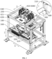
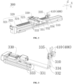
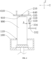
- 100-conveying unit 200-second detection unit, 210-second temperature probe, 300-first detection unit, 310-first temperature probe, 320-first moving assembly, 321-first driver, 322-sliding rail, 323-sliding block, 324-drag chain, 330-second moving assembly, 331-second driver, 332-movable member, 333-sensor, 334-guide rod, 335-fixing bracket, 400-trigger unit, 410-micro switch, 500-rack, 600-third detection unit, 610-probe plate, 620-fixed plate, 630-third driver, 900-device to be detected, 910-electrode terminal.
- the term "and/or” is simply a description of an association relationship between associated objects, which indicates that there may be three relationships, for example, A and/or B may mean: the presence of A, the presence of both A and B, and the presence of B.
- a and/or B may mean: the presence of A, the presence of both A and B, and the presence of B.
- the character "/" herein generally means that the associated objects before and after it are in an "or" relationship.
- the meaning of “multiple” refers to at least two (including two), such as two and three, unless otherwise explicitly and specifically defined.
- the meaning of “multiple groups” refers to more than two groups (including two groups); and if the term “multiple pieces” appears, the meaning of “multiple pieces” refers to more than two pieces (including two pieces).
- orientation or position relationships indicated by the terms are orientation or position relationships based on the drawings.
- connection may be fixed connection, detachable connection, or integrated connection, or may be mechanical connection or electrical connection, or may be direct connection, indirect connection through an intermediate medium, internal communication between two elements, or interaction relationship between two elements.
- connection may be fixed connection, detachable connection, or integrated connection, or may be mechanical connection or electrical connection, or may be direct connection, indirect connection through an intermediate medium, internal communication between two elements, or interaction relationship between two elements.
- first feature being “on” or “under” a second feature
- the expression may be the case that the first feature is in direct contact with the second feature, or the first feature is in indirect contact with the second feature through an intermediate medium.
- first feature being “over,” “above” and “on” the second feature may mean that the first feature is directly above or obliquely above the second feature, or only means that the level of the first feature is higher than that of the second feature.
- the first feature being “below”, “underneath” or “under” the second feature may mean that the first feature is directly underneath or obliquely underneath the second feature, or only means that the level of the first feature is lower than that of the second feature.
- Power batteries are more and more widely used.
- Power batteries are used in energy storage power systems such as hydraulic, thermal, wind and solar power stations, and are widely used in electric vehicles such as electric bicycles, electric motorcycles and electric cars, as well as in multiple fields such as aerospace. With the continuous expansion of the application field of power batteries, the market demand is also constantly expanding.
- Detection items are a checkpoint for the safety inspection of battery cells, and are crucial to control the safety of products.
- a conveying unit conveys the battery cells to detection stations of the corresponding positions during the conveying process. Regions to be detected of the battery cells have distance and position differences according to different thicknesses, heights or placement angles of the battery cells at the detection stations.
- a temperature detection unit for battery cells in a detection mechanism targets multiple types of battery cells simultaneously, a too far or too close distance between a precise temperature probe and a region to be detected may affect the detection accuracy. Moreover, it is necessary to consider that the interference between the precise temperature probe and the battery cell may cause damage, resulting in poor universality.
- a trigger unit may be arranged to detect battery cells conveyed by the conveying unit at detection stations, thereby increasing the universality.
- the temperature of a large surface on a side of a battery cell and the temperature of a terminal on a top surface of the battery cell are detected simultaneously at the same station, thereby increasing the detection efficiency.
- the inventors have designed a detection mechanism which can be configured to detect battery cells to be detected.
- the temperature detection of the battery cells can be implemented by conveying the battery cells to the corresponding detection stations. Considering the position difference between the battery cells during the conveying process, collision or position deviation can be prevented by controlling the distance between the battery cells and the detection mechanism.
- the battery disclosed in the embodiments of the present application refers to a single physical module including one or a plurality of battery cells to provide a higher voltage and capacity.
- the battery mentioned in the present application may include a battery pack and the like.
- Some batteries may include separate box for encapsulating one or more battery cells or a plurality of battery modules. The box can prevent liquids or other foreign matters from affecting the charging or discharging of the battery cell.
- some batteries may not include the above separate box, and a battery cell or battery module is directly arranged in a battery mounting compartment of an electrical apparatus, that is, the battery mounting compartment serves as a box.
- the battery disclosed in the embodiments of the present application can be used in, but not limited to, an electrical apparatus such as a vehicle, a ship or an aircraft.
- a power system of the electrical apparatus may be composed of the battery cell, the battery, and the like disclosed in the present application.
- the battery cell may include a lithium-ion secondary battery, a lithium-ion primary battery, a lithium-sulfur battery, a sodium/lithium-ion battery, a sodium-ion battery, a magnesium-ion battery, or the like, which is not limited in the embodiments of the present application.
- the battery cell may be cylindrical, flat, rectangular, or in other shapes, which is not limited in the embodiments of the present application. Battery cells are generally divided into three types according to encapsulating manners: cylindrical battery cells, square battery cells, and pouch cells, which are not limited in the embodiments of the present application.
- the battery cell may include a shell, an electrode assembly, and an electrolyte.
- the shell may be provided with functional components such as an electrode terminal.
- the electrode terminal may be electrically connected to the electrode assembly to output or input the electric energy of the battery cell.
- An internal environment formed in the shell may be used for accommodating the electrode assembly, the electrolyte, and other components.
- the electrode assembly is a component in which an electrochemical reaction occurs in the battery cell.
- the shell may include one or more electrode assemblies inside.
- the electrode assembly is mainly formed by winding or stacking a positive electrode plate and a negative electrode plate, and a separator is usually arranged between the positive electrode plate and the negative electrode plate.
- the positive electrode plate includes a positive electrode current collector and a positive electrode active material layer, the positive electrode active material layer is coated on a surface of the positive electrode current collector, the positive electrode current collector which is not coated with the positive electrode active material layer protrudes from the positive electrode current collector coated with the positive electrode active material layer, and the positive electrode current collector which is not coated with the positive electrode active material layer is used as a positive tab.
- the material of the positive electrode current collector may be aluminum, and the positive electrode active material may be lithium cobalt oxide, lithium iron phosphate, ternary lithium, lithium manganate, or the like.
- the negative electrode plate includes a negative electrode current collector and a negative electrode active material layer, the negative electrode active material layer is coated on a surface of the negative electrode current collector, the negative electrode current collector which is not coated with the negative electrode active material layer protrudes from the negative electrode current collector which is coated with the negative electrode active material layer, and the negative electrode current collector which is not coated with the negative electrode active material layer is used as a negative tab.
- the material of the negative electrode current collector may be copper, and the negative electrode active material may be carbon, silicon, or the like.
- the material of the separator may be polypropylene (PP), polyethylene (PE), or the like.
- the electrode assembly may be of a wound structure or a stacked structure, which is not limited in the embodiments of the present application.
- the first aspect of the present application provides a detection mechanism configured to detect a device to be detected 900.
- Detection items may include, but are not limited to, temperature.
- the device to be detected 900 may be a battery cell, an electrode assembly, or a battery.
- the device to be detected 900 being one or more battery cells, is taken as an example for illustration.
- a detection mechanism includes: a conveying unit 100, a first detection unit 300, and a trigger unit 400.
- the conveying unit 100 is configured to convey the device to be detected 900.
- the conveying unit 100 is provided with one or more carriers, and each carrier is provided with a positioning slot 110 suitable for carrying the device to be detected 900.
- the conveying unit 100 moves according to a specified path, and then, the device to be detected 900, carried by the carrier, can move according to the specified path and move to a detection station in the detection mechanism, thereby ensuring that the device to be detected 900 on the detection station can be smoothly detected by the first detection unit 300, and the loading and unloading can be smoothly achieved.
- the conveying unit 100 may be a conveying belt, a sliding rail, a magnetic suspension track, or the like.
- the first detection unit 300 is configured to detect the temperature of the device to be detected 900.
- the trigger unit 400 is configured to detect the distance A between the first detection unit 300 and the device to be detected 900.
- the trigger unit 400 controls the conveying unit 100 to stop conveying.
- the preset distance value can be set respectively according to different models and types of the device to be detected 900, and the value can be obtained in advance through limited data accumulations, calculated theoretically, or given by designers.
- the conveying unit 100 is arranged to convey the device to be detected 900
- the first detection unit 300 is arranged to detect the device to be detected 900 instead of a manual operation
- the trigger unit 400 is arranged to detect the distance A between the first detection unit 300 and the device to be detected 900. In this way, it can be ensured that a suitable detection distance is always maintained between the device to be detected 900 and the first detection unit 300, so the measured data is more accurate.
- the trigger unit 400 can control the conveying unit 100 to stop conveying so as to avoid generation of temperature data with larger errors, and also avoid the interference between the device to be detected 900 and the first detection unit 300 in time, so the universality of the detection mechanism is better.
- the temperature detection of a large surface on a side of a battery cell and the temperature detection of a terminal on a top surface of the battery cell are divided into two stations, resulting in low space utilization rate.
- the detection mechanism includes a second detection unit 200; the second detection unit 200 is configured to detect the temperature of a top surface of the device to be detected 900; and the first detection unit 300 is configured to detect the temperature of a side surface of the device to be detected 900.
- the second detection unit 200 can be configured to detect the temperature of a top surface of the device to be detected 900. That is, when the device to be detected 900 is conveyed from the conveying unit 100 to a detection station, the second detection unit 200 detects the temperature of the device to be detected 900 at the detection station.
- the detected part includes at least one of a top surface of the shell of the device to be detected 900 (that is, an upper end surface with an electrode terminal 910 on the shell; correspondingly, a lower end surface without a terminal on the shell can be considered as a bottom surface), and components arranged on the top surface (including, but not limited to, the electrode terminal 910, an explosion-proof pressure relief valve, and the like).
- the temperature detection here can be performed by a contact type temperature sensor and an infrared temperature sensor.
- the first detection unit 300 is configured to detect the temperature of a side surface of the device to be detected 900. That is, when the device to be detected 900 is conveyed from the conveying unit 100 to a detection station, the first detection unit 3000 detects the temperature of the device to be detected 900 at the detection station.
- the detected part includes at least one of a side surface of the shell of the device to be detected 900, and components arranged on the side surface.
- the shell of the device to be detected 900 includes a plurality of enclosed side surfaces connected between the top surface and the bottom surface of the shell of the device to be detected 900, where in the plurality of side surfaces, a side surface with a relatively large area is a large side surface, and a side surface with a relatively small area is a connecting surface. If the device to be detected 900 is a cylindrical battery cell, a peripheral surface connected between the top surface and the bottom surface of the shell of the device to be detected 900 is a side surface.
- the conveying unit 100 is arranged to convey the device to be detected 900, and the second detection unit 200 at the top and the first detection unit 300 on the side are arranged to detect the temperature of the top surface and the temperature of the side surface of the device to be detected 900 instead of a manual operation.
- the efficiency is higher, safety accidents caused by defects of the device to be detected 900 are avoided, and the safety performance is improved.
- the detection mechanism includes a rack 500; the first detection unit 300 is movably arranged on a side of the rack 500; the second detection unit 200 is movably arranged at the top of the rack 500; and the conveying unit 100 passes through the rack 500.
- the first detection unit 300 may include a first moving assembly 320, a second moving assembly 330, and a first temperature probe 310.
- the first moving assembly 320 is movably arranged on the rack 500 along an X-axis direction
- the second moving assembly 330 is movably arranged on the first moving assembly 320 along a Y-axis direction
- the first temperature probe 310 is movably arranged on the second moving assembly 330 along a Z-axis direction.
- the position of the first temperature probe 310 on the first detection unit 300 can be adjusted through the first moving assembly 320 and the second moving assembly 330, so that the distance A between the first temperature probe 310 and the device to be detected 900 is maintained in a suitable scope, and the detection accuracy of the first temperature probe 310 is ensured.
- the trigger unit 400 controls the conveying unit 100 to stop conveying, so as to avoid larger errors in the temperature data of the first temperature probe 310, and also avoid the interference between the device to be detected 900 and the first temperature probe 310 in time.
- the first temperature probe 310 is an infrared temperature probe.
- the infrared temperature probe has certain requirements for a measuring distance.
- the trigger unit 400 is arranged to control the conveying unit 100 to stop conveying in time, so as to avoid the infrared temperature probe from generating temperature data with larger errors, also avoid the collision between the device to be detected 900 and the first detection unit 300 in time, and finally avoid the damage to the detection mechanism.
- the direction of the top surface of the device to be detected 900 pointing to the bottom surface is the Z-axis direction, the X-axis direction, the Y-axis direction and Z-axis direction intersect with each other, and an intersection angle may be 90° or slightly larger or smaller.
- the device to be detected 900 can be arranged vertically.
- the Z-axis direction is the vertical direction
- the X-axis direction and the Y-axis direction may be two horizontal directions that intersect vertically in the horizontal plane.
- the trigger unit 400 includes a micro switch 410 and a controller (not shown); the micro switch 410 is configured to detect the distance A between the first detection unit 300 and the device to be detected 900; the micro switch 410 is in signal connection with the controller; and when the distance between the first detection unit 300 and the device to be detected 900 is less than the preset distance value, the controller controls the conveying unit 100 to stop conveying.
- the controller of the trigger unit 400 may be a CPU.
- the controller can be in signal connection with a second temperature probe 210 (mentioned below) of the second detection unit 200, a first temperature probe 310 (mentioned below) of the first detection unit 300, and the micro switch 410 to collect the corresponding data.
- the controller controls and is connected to the conveying unit 100, a first driver 321 (mentioned below) of the first moving assembly 320, a second driver 331 (mentioned below) of the second moving assembly 330, and a third driver 630 (mentioned below) of a third detection unit 600 (mentioned below). Therefore, the controller coordinates the actions of various moving components according to the collected corresponding data.
- the conveying unit 100 passes through the rack 500 along the X-axis direction.
- the first detection unit 3000 detects the temperature of the side surface of the device to be detected 900
- the second detection unit 200 detects the temperature of the top surface of the device to be detected 900 at the detection station.
- the manual operation can be replaced to detect the temperature of the top surface and the temperature of the side surface of the device to be detected 900, there are more comprehensive detection items, and the efficiency is higher.
- the trigger unit 400 may be arranged on one side or two opposite sides of the first temperature probe 310 along the X-axis direction.
- the micro switch 410 of the trigger unit 400 may be arranged on one side of the first temperature probe 310 along the X-axis direction.
- the conveying unit 100 conveys the device to be detected 900 to one side along the X-axis direction, thus the micro switch 410 can detect the device to be detected 900 on the conveying unit 100 before the first temperature probe 310 to prevent collision.
- the micro switch 410 of the trigger unit 400 may be arranged on two opposite sides of the first temperature probe 310 along the X-axis direction.
- the conveying unit 100 conveys the device to be detected 900 to any side along the X-axis direction.
- the micro switch 410 can detect the device to be detected 900 on the conveying unit 100 before the first temperature probe 310 to prevent collision, thus being beneficial for the normal production of the battery production line or reversion the conveying belt in other situations.
- the first moving assembly 320 includes a first driver 321, a sliding rail 322, and a sliding block 323; the sliding rail 322 extends along the X-axis direction and is fixed to the rack 500; the sliding block 323 is slidably arranged on the sliding rail 322; and the first driver 321 can drive the sliding block 323 to reciprocate relative to the sliding rail 322.
- the first driver 321 may be a servo motor or a cylinder. Taking the servo motor as an example, a programmable logic controller (PLC) (not shown) is configured to control the first driver 321, resulting in higher motion accuracy. In this way, the sliding block 323 can be accurately driven to move along the X-axis direction relative to the sliding rail 322, so that the positions of the second moving assembly 330 and the first temperature probe 310 in the X-axis direction can be adjusted.
- PLC programmable logic controller
- the second moving assembly 330 includes a second driver 331 and a movable member 332; the second driver 331 is fixedly arranged on the sliding block 323; and the second driver 331 is capable of driving the movable member 332 to reciprocate along the Y-axis direction.
- the first temperature probe 310 may be movably arranged at an end of the movable member 332 along the Z-axis direction.
- the movable member 332 may be a rod piece or a plate body.
- the second driver 331 may be a cylinder or a servo motor. Taking the cylinder as an example, a telescopic rod in a cylinder body of the second driver 331 is arranged along the Y-axis direction.
- the telescopic rod of the second driver 331 drives the movable member 332 to extend along the Y-axis direction; and with reference to the orientation shown in FIG. 4 , the movable member 332 drives the first temperature probe 310 to move leftwards along the Y-axis direction, equivalent to being close to the device to be detected 900.
- the telescopic rod of the second driver 331 drives the movable member 332 to retract along the Y-axis direction; and with reference to the orientation shown in FIG. 4 , the movable member 332 drives the first temperature probe 310 to move rightwards along the Y-axis direction, equivalent to being away from the device to be detected 900.
- the distance A between the first temperature probe 310 and the device to be detected 900 along the Y-axis direction can be adjusted in time by arranging the second driver 331 and the movable member 332, and then, a suitable detection distance is always maintained between the device to be detected 900 and the first detection unit 300, so that the measured data is more accurate, and unnecessary collision can also be avoided.
- the first moving assembly 320 includes a drag chain 324, and the first driver 321 is electrically connected to the outside through the drag chain 324.
- a cable or an air pipe for the first driver 321 and the second driver 331 are arranged in the drag chain 324.
- the drag chain 324 plays roles in traction and protection of the cable or the air pipe, thereby prolonging the service life of the detection mechanism.
- the second driver 331 may be a servo motor.
- the second moving assembly 330 includes a sensor 333, and the sensor 333 is configured to sense the position of the movable member 332 along the Y-axis direction.
- the sensor 333 may be a photoelectric sensor or an electromagnetic sensor.
- the second moving assembly 330 may include three sensors 333, and the three sensors 333 are sequentially arranged on the body of the second driver 331 along the Y-axis direction to sense the position of the movable member 332 along the Y-axis direction.
- the position of the Y-axis direction corresponding to the intermediate sensor 333 may be set as an original point.
- the position of the Y-axis direction corresponding to the sensor 333 away from the first moving assembly 320 is the farthest point where the movable member 332 extends along the Y-axis direction, and at this time, the value of the distance A is minimum.
- the position of the Y-axis direction corresponding to the sensor 333 close to the first moving assembly 320 is the closest point where the movable member 332 retracts along the Y-axis direction, and at this time, the value of the distance A is maximum.
- the PLC can be flexibly used to control the point position of the second driver 331 and accurately control the positions of both ends based on the original point.
- the second moving assembly 330 includes a guide rod 334 extending along the Z-axis direction and a fixing bracket 335, and the guide rod 334 is arranged on the movable member 332.
- the fixing bracket 335 is movably arranged on the guide rod 334, and the first temperature probe 310 is fixedly arranged on the fixing bracket 335.
- the guide rod 334 usually can be arranged at an end of the movable member 332 to avoid collision between the protruding movable member 332 and the device to be detected 900.
- the first temperature probe 310 is fixedly arranged on the fixing bracket 335.
- the micro switch 410 can be arranged on the fixing bracket 335 through a bolt or other structures, and located on one side or both sides of the first temperature probe 310 along the X-axis direction.
- the fixing bracket 335 adjusts the distance relative to the guide rod 334 along the Z-axis direction
- the micro switch 410 and the first temperature probe 310 can together adjust the positions in the X-axis direction, the Y-axis direction and the Z-axis direction, and the micro switch 410 and the first temperature probe 310 are relatively fixed to ensure that the micro switch 410 can detect the device to be detected 900 on the conveying unit 100 before the first temperature probe 310 to prevent collision.
- the trigger unit 400 further includes an alarm apparatus (not shown), and the controller controls and is connected to the alarm apparatus.
- the controller controls the conveying unit 100 to stop conveying and can control the alarm apparatus to give a corresponding alarm to remind operators to eliminate faults.
- the detection mechanism further includes a third detection unit 600; and the third detection unit 600 is arranged at the top of the rack 500 and configured to perform dielectric voltage withstand test on the electrode terminal 910 on the top surface of the device to be detected 900.
- the third detection unit 600 applies a voltage to the device to be detected 900 and maintains the voltage for a certain period of time, and then detects whether the magnitude of the leakage current is maintained in the specified range to determine whether there is a short circuit between positive and negative electrodes of a battery cell.
- the applied voltage is 800-1500 V.
- the third detection unit 600 includes a probe plate 610, a fixed plate 620, and a third driver 630; the fixed plate 620 is erected at the top of the rack 500; the probe plate 610 is movably arranged relative to the fixed plate 620; the third driver 630 is configured to drive the probe plate 610 to be close to or away from the electrode terminal 910 on the top surface of the device to be detected 900 along the Z-axis direction; and the probe plate 610 is configured to perform dielectric voltage withstand test on the electrode terminal 910 on the top surface of the device to be detected 900.
- the probe plate 610 may be a metallic conductor plate, such as a copper plate, a copper clad steel plate, or an aluminum plate.
- the probe plate 610 is located below the fixed plate 620 along the Z-axis direction and is movably arranged.
- the third driver 630 may be a cylinder or a motor.
- the fixed plate 620 may be provided with a guide cylinder 621, one end of a guide post 640 is connected to the probe plate 610, and the guide post 640 can be inserted into the guide cylinder 621.
- the guide post 640 is guided by the guide cylinder 621 to enable the probe plate 610 to be close to or away from the electrode terminal 910 on the top surface of the device to be detected 900 along the Z-axis direction.
- a power supply assembly (not shown) in the third detection unit 600 applies a preset voltage to the probe plate 610 and maintains the preset voltage for a certain period of time, and then detects whether the magnitude of the leakage current is maintained in the specified range to determine whether there is a short circuit between positive and negative electrodes of a battery cell.
- the preset voltage is 1000 V.
- the probe plate 610 moves upwards along the Z-axis direction and then is separated from the electrode terminal 910 of the device to be detected 900.
- the second detection unit 200 is arranged on the probe plate 610; and when the probe plate 610 is close to the electrode terminal 910 on the top surface of the device to be detected 900, the second detection unit 200 detects the temperature of the electrode terminal 910 on the top surface of the device to be detected 900.
- the second temperature probe 210 of the second detection unit 200 is also in contact with the electrode terminal 910.
- the third detection unit 600 performs dielectric voltage withstand test on the device to be detected 900, and the second temperature probe 210 of the second detection unit 200 detects the temperature of the electrode terminal 910 on the top surface of the device to be detected 900, thereby increasing the detection efficiency, and improving the takt time.
- different detection mechanisms in related technologies can be combined, so that the detection mechanism of the present application can achieve three purposes.
- the second detection unit 200 includes at least one second temperature probe 210.
- second temperature probes 210 may be distributed on the second detection unit 200, the number of the second temperature probes 210 may be different according to different numbers of electrode assemblies in a battery cell, and each second temperature probe 210 is in signal connection with the controller respectively.
- the probe plate 610 is in contact with the electrode terminal 910 of the device to be detected 900, multiple second temperature probes 210 can measure the temperatures of terminals on different electrode assemblies respectively.
- the second temperature probe 210 may be a contact type temperature probe which has the advantages of high detection accuracy and high temperature resistance.
- the second temperature probe 210 may also be an infrared temperature probe depending on the specific design.
- the second aspect of the present application provides a battery production line, including the above detection mechanism.
Landscapes
- Physics & Mathematics (AREA)
- General Physics & Mathematics (AREA)
- Spectroscopy & Molecular Physics (AREA)
- Engineering & Computer Science (AREA)
- Manufacturing & Machinery (AREA)
- Chemical & Material Sciences (AREA)
- Chemical Kinetics & Catalysis (AREA)
- Electrochemistry (AREA)
- General Chemical & Material Sciences (AREA)
- Secondary Cells (AREA)
Applications Claiming Priority (1)
| Application Number | Priority Date | Filing Date | Title |
|---|---|---|---|
| PCT/CN2023/101801 WO2024259657A1 (fr) | 2023-06-21 | 2023-06-21 | Mécanisme de mesure et chaîne de production de batterie |
Publications (2)
| Publication Number | Publication Date |
|---|---|
| EP4509848A4 EP4509848A4 (fr) | 2025-02-19 |
| EP4509848A1 true EP4509848A1 (fr) | 2025-02-19 |
Family
ID=93928462
Family Applications (1)
| Application Number | Title | Priority Date | Filing Date |
|---|---|---|---|
| EP23802139.8A Pending EP4509848A1 (fr) | 2023-06-21 | 2023-06-21 | Mécanisme de mesure et chaîne de production de batterie |
Country Status (4)
| Country | Link |
|---|---|
| US (1) | US20240425294A1 (fr) |
| EP (1) | EP4509848A1 (fr) |
| CN (1) | CN119866448B (fr) |
| WO (1) | WO2024259657A1 (fr) |
Families Citing this family (2)
| Publication number | Priority date | Publication date | Assignee | Title |
|---|---|---|---|---|
| CN120427982B (zh) * | 2025-05-27 | 2025-12-02 | 山东国信电力科技有限公司 | 一种配电设备用接触器触点电阻检测装置 |
| CN120468701B (zh) * | 2025-06-06 | 2026-01-09 | 苏州锐洁新能源有限公司 | 一种电池包健康诊断设备及电池包健康检测方法 |
Family Cites Families (8)
| Publication number | Priority date | Publication date | Assignee | Title |
|---|---|---|---|---|
| JP2018087735A (ja) * | 2016-11-29 | 2018-06-07 | セイコーエプソン株式会社 | 電子部品搬送装置および電子部品検査装置 |
| CN215930844U (zh) * | 2021-09-29 | 2022-03-01 | 斯德拉马机械(太仓)有限公司 | 一种电池涂层厚度检测装置 |
| CN217505684U (zh) * | 2022-03-29 | 2022-09-27 | 宁德时代新能源科技股份有限公司 | 外观检测装置、外观检测设备及电池单体外观检测设备 |
| CN217504735U (zh) * | 2022-05-20 | 2022-09-27 | 宁德时代新能源科技股份有限公司 | 工装夹具及模组生产系统 |
| CN115077396A (zh) * | 2022-06-16 | 2022-09-20 | 深圳市新威尔电子有限公司 | 全自动电池性能检测机构 |
| CN217931435U (zh) * | 2022-09-09 | 2022-11-29 | 宁德时代新能源科技股份有限公司 | 检测装置 |
| CN218956652U (zh) * | 2023-01-10 | 2023-05-02 | 宁德时代新能源科技股份有限公司 | 电池托盘、电池的测试系统 |
| CN219066893U (zh) * | 2022-12-13 | 2023-05-23 | 横店集团东磁股份有限公司 | 电池内部短路检测装置 |
-
2023
- 2023-06-21 EP EP23802139.8A patent/EP4509848A1/fr active Pending
- 2023-06-21 CN CN202380066566.1A patent/CN119866448B/zh active Active
- 2023-06-21 WO PCT/CN2023/101801 patent/WO2024259657A1/fr not_active Ceased
- 2023-10-30 US US18/497,923 patent/US20240425294A1/en active Pending
Also Published As
| Publication number | Publication date |
|---|---|
| CN119866448B (zh) | 2026-03-03 |
| US20240425294A1 (en) | 2024-12-26 |
| WO2024259657A1 (fr) | 2024-12-26 |
| CN119866448A (zh) | 2025-04-22 |
Similar Documents
| Publication | Publication Date | Title |
|---|---|---|
| US20240425294A1 (en) | Detection mechanism and battery production line | |
| US20240243444A1 (en) | Electrode plate, electrode assembly, battery cell, battery, and electric device | |
| US20230261244A1 (en) | Case-put-in apparatus and battery assembling device | |
| EP4498488A1 (fr) | Capuchon d'extrémité, cellule de batterie, batterie et dispositif électrique | |
| US12491588B2 (en) | Welding positioning apparatus, battery production line, and welding method | |
| US20210218116A1 (en) | Battery system with flexible printed circuit | |
| CN104185911B (zh) | 母线安装装置和母线安装方法 | |
| EP4456267A1 (fr) | Élément de batterie et son procédé de fabrication, dispositif, batterie et appareil électrique | |
| US12472622B2 (en) | Transfer apparatus | |
| US11309603B2 (en) | Square secondary battery, battery module, storage device, vehicle, and flying object | |
| US20240339626A1 (en) | Electrode assembly, battery cell, battery, and electric device | |
| KR20150033269A (ko) | 배터리 팩의 크기 측정장치 | |
| US12494519B2 (en) | Secondary battery and detecting system | |
| CN222914878U (zh) | 电池及用电装置 | |
| KR20230125673A (ko) | 셀 이송 장치 및 이를 포함하는 셀 이송 시스템 | |
| CN222573393U (zh) | 电池运输设备 | |
| CN224109462U (zh) | 电极组件外观检测设备和电池生产线 | |
| US20240106083A1 (en) | Battery system with flexible printed circuit | |
| US20240021897A1 (en) | Sampling assembly and manufacturing method thereof, battery, and electric device | |
| US20260074265A1 (en) | Assembly apparatus and assembly method | |
| US20240274963A1 (en) | Positioning apparatus and method for battery, compartment base, battery swapping station, and electrical apparatus | |
| CN223757523U (zh) | 电池单体、电池装置和用电装置 | |
| EP4568023A1 (fr) | Connecteur, appareil, batterie et dispositif électrique | |
| US20250132435A1 (en) | Case, battery module comprising case, and manufacturing method of case | |
| US20230361436A1 (en) | Battery, electric device, and manufacturing method and manufacturing device of battery |
Legal Events
| Date | Code | Title | Description |
|---|---|---|---|
| STAA | Information on the status of an ep patent application or granted ep patent |
Free format text: STATUS: UNKNOWN |
|
| STAA | Information on the status of an ep patent application or granted ep patent |
Free format text: STATUS: THE INTERNATIONAL PUBLICATION HAS BEEN MADE |
|
| PUAI | Public reference made under article 153(3) epc to a published international application that has entered the european phase |
Free format text: ORIGINAL CODE: 0009012 |
|
| STAA | Information on the status of an ep patent application or granted ep patent |
Free format text: STATUS: REQUEST FOR EXAMINATION WAS MADE |
|
| 17P | Request for examination filed |
Effective date: 20231117 |
|
| A4 | Supplementary search report drawn up and despatched |
Effective date: 20240619 |
|
| AK | Designated contracting states |
Kind code of ref document: A1 Designated state(s): AL AT BE BG CH CY CZ DE DK EE ES FI FR GB GR HR HU IE IS IT LI LT LU LV MC ME MK MT NL NO PL PT RO RS SE SI SK SM TR |