EP4509864A1 - Détection radar améliorée utilisant des informations d'objet suivies antérieures - Google Patents
Détection radar améliorée utilisant des informations d'objet suivies antérieures Download PDFInfo
- Publication number
- EP4509864A1 EP4509864A1 EP24190666.8A EP24190666A EP4509864A1 EP 4509864 A1 EP4509864 A1 EP 4509864A1 EP 24190666 A EP24190666 A EP 24190666A EP 4509864 A1 EP4509864 A1 EP 4509864A1
- Authority
- EP
- European Patent Office
- Prior art keywords
- range
- doppler
- candidate
- antenna data
- object information
- Prior art date
- Legal status (The legal status is an assumption and is not a legal conclusion. Google has not performed a legal analysis and makes no representation as to the accuracy of the status listed.)
- Pending
Links
Images



Classifications
-
- G—PHYSICS
- G01—MEASURING; TESTING
- G01S—RADIO DIRECTION-FINDING; RADIO NAVIGATION; DETERMINING DISTANCE OR VELOCITY BY USE OF RADIO WAVES; LOCATING OR PRESENCE-DETECTING BY USE OF THE REFLECTION OR RERADIATION OF RADIO WAVES; ANALOGOUS ARRANGEMENTS USING OTHER WAVES
- G01S13/00—Systems using the reflection or reradiation of radio waves, e.g. radar systems; Analogous systems using reflection or reradiation of waves whose nature or wavelength is irrelevant or unspecified
- G01S13/66—Radar-tracking systems; Analogous systems
- G01S13/72—Radar-tracking systems; Analogous systems for two-dimensional [2D] tracking, e.g. combination of angle and range tracking, track-while-scan radar
- G01S13/723—Radar-tracking systems; Analogous systems for two-dimensional [2D] tracking, e.g. combination of angle and range tracking, track-while-scan radar by using numerical data
- G01S13/726—Multiple target tracking
-
- G—PHYSICS
- G01—MEASURING; TESTING
- G01S—RADIO DIRECTION-FINDING; RADIO NAVIGATION; DETERMINING DISTANCE OR VELOCITY BY USE OF RADIO WAVES; LOCATING OR PRESENCE-DETECTING BY USE OF THE REFLECTION OR RERADIATION OF RADIO WAVES; ANALOGOUS ARRANGEMENTS USING OTHER WAVES
- G01S7/00—Details of systems according to groups G01S13/00, G01S15/00, G01S17/00
- G01S7/02—Details of systems according to groups G01S13/00, G01S15/00, G01S17/00 of systems according to group G01S13/00
- G01S7/41—Details of systems according to groups G01S13/00, G01S15/00, G01S17/00 of systems according to group G01S13/00 using analysis of echo signal for target characterisation; Target signature; Target cross-section
-
- G—PHYSICS
- G01—MEASURING; TESTING
- G01S—RADIO DIRECTION-FINDING; RADIO NAVIGATION; DETERMINING DISTANCE OR VELOCITY BY USE OF RADIO WAVES; LOCATING OR PRESENCE-DETECTING BY USE OF THE REFLECTION OR RERADIATION OF RADIO WAVES; ANALOGOUS ARRANGEMENTS USING OTHER WAVES
- G01S13/00—Systems using the reflection or reradiation of radio waves, e.g. radar systems; Analogous systems using reflection or reradiation of waves whose nature or wavelength is irrelevant or unspecified
- G01S13/02—Systems using reflection of radio waves, e.g. primary radar systems; Analogous systems
- G01S13/06—Systems determining position data of a target
- G01S13/08—Systems for measuring distance only
- G01S13/32—Systems for measuring distance only using transmission of continuous waves, whether amplitude-, frequency-, or phase-modulated, or unmodulated
- G01S13/34—Systems for measuring distance only using transmission of continuous waves, whether amplitude-, frequency-, or phase-modulated, or unmodulated using transmission of continuous, frequency-modulated waves while heterodyning the received signal, or a signal derived therefrom, with a locally-generated signal related to the contemporaneously transmitted signal
- G01S13/343—Systems for measuring distance only using transmission of continuous waves, whether amplitude-, frequency-, or phase-modulated, or unmodulated using transmission of continuous, frequency-modulated waves while heterodyning the received signal, or a signal derived therefrom, with a locally-generated signal related to the contemporaneously transmitted signal using sawtooth modulation
-
- G—PHYSICS
- G01—MEASURING; TESTING
- G01S—RADIO DIRECTION-FINDING; RADIO NAVIGATION; DETERMINING DISTANCE OR VELOCITY BY USE OF RADIO WAVES; LOCATING OR PRESENCE-DETECTING BY USE OF THE REFLECTION OR RERADIATION OF RADIO WAVES; ANALOGOUS ARRANGEMENTS USING OTHER WAVES
- G01S13/00—Systems using the reflection or reradiation of radio waves, e.g. radar systems; Analogous systems using reflection or reradiation of waves whose nature or wavelength is irrelevant or unspecified
- G01S13/02—Systems using reflection of radio waves, e.g. primary radar systems; Analogous systems
- G01S13/50—Systems of measurement based on relative movement of target
- G01S13/58—Velocity or trajectory determination systems; Sense-of-movement determination systems
- G01S13/583—Velocity or trajectory determination systems; Sense-of-movement determination systems using transmission of continuous unmodulated waves, amplitude-, frequency-, or phase-modulated waves and based upon the Doppler effect resulting from movement of targets
- G01S13/584—Velocity or trajectory determination systems; Sense-of-movement determination systems using transmission of continuous unmodulated waves, amplitude-, frequency-, or phase-modulated waves and based upon the Doppler effect resulting from movement of targets adapted for simultaneous range and velocity measurements
-
- G—PHYSICS
- G01—MEASURING; TESTING
- G01S—RADIO DIRECTION-FINDING; RADIO NAVIGATION; DETERMINING DISTANCE OR VELOCITY BY USE OF RADIO WAVES; LOCATING OR PRESENCE-DETECTING BY USE OF THE REFLECTION OR RERADIATION OF RADIO WAVES; ANALOGOUS ARRANGEMENTS USING OTHER WAVES
- G01S13/00—Systems using the reflection or reradiation of radio waves, e.g. radar systems; Analogous systems using reflection or reradiation of waves whose nature or wavelength is irrelevant or unspecified
- G01S13/66—Radar-tracking systems; Analogous systems
-
- G—PHYSICS
- G01—MEASURING; TESTING
- G01S—RADIO DIRECTION-FINDING; RADIO NAVIGATION; DETERMINING DISTANCE OR VELOCITY BY USE OF RADIO WAVES; LOCATING OR PRESENCE-DETECTING BY USE OF THE REFLECTION OR RERADIATION OF RADIO WAVES; ANALOGOUS ARRANGEMENTS USING OTHER WAVES
- G01S3/00—Direction-finders for determining the direction from which infrasonic, sonic, ultrasonic or electromagnetic waves, or particle emission, not having a directional significance, are being received
- G01S3/02—Direction-finders for determining the direction from which infrasonic, sonic, ultrasonic or electromagnetic waves, or particle emission, not having a directional significance, are being received using radio waves
- G01S3/14—Systems for determining direction or deviation from predetermined direction
-
- G—PHYSICS
- G01—MEASURING; TESTING
- G01S—RADIO DIRECTION-FINDING; RADIO NAVIGATION; DETERMINING DISTANCE OR VELOCITY BY USE OF RADIO WAVES; LOCATING OR PRESENCE-DETECTING BY USE OF THE REFLECTION OR RERADIATION OF RADIO WAVES; ANALOGOUS ARRANGEMENTS USING OTHER WAVES
- G01S7/00—Details of systems according to groups G01S13/00, G01S15/00, G01S17/00
- G01S7/02—Details of systems according to groups G01S13/00, G01S15/00, G01S17/00 of systems according to group G01S13/00
- G01S7/35—Details of non-pulse systems
- G01S7/352—Receivers
- G01S7/356—Receivers involving particularities of FFT processing
-
- G—PHYSICS
- G01—MEASURING; TESTING
- G01S—RADIO DIRECTION-FINDING; RADIO NAVIGATION; DETERMINING DISTANCE OR VELOCITY BY USE OF RADIO WAVES; LOCATING OR PRESENCE-DETECTING BY USE OF THE REFLECTION OR RERADIATION OF RADIO WAVES; ANALOGOUS ARRANGEMENTS USING OTHER WAVES
- G01S13/00—Systems using the reflection or reradiation of radio waves, e.g. radar systems; Analogous systems using reflection or reradiation of waves whose nature or wavelength is irrelevant or unspecified
- G01S13/88—Radar or analogous systems specially adapted for specific applications
- G01S13/93—Radar or analogous systems specially adapted for specific applications for anti-collision purposes
- G01S13/931—Radar or analogous systems specially adapted for specific applications for anti-collision purposes of land vehicles
Definitions
- Some radar systems are included in vehicles as part of automated driving assistance systems and used to assist in perception of environments around the vehicles. To accurately represent the environment, a radar system performs peak detection to identify objects. However, performing peak detection based on a constant detection threshold within each range bin can lead to false negative detections where a signal strength of radar reflections off an object is close to a noise floor.
- some techniques for performing peak detection can lead to false negative detections where a signal strength of radar reflections off an object is close to a noise floor of the radar system.
- the disclosed techniques and radar systems implementing the disclosed techniques are able to adapt a detection threshold based on information about tracked objects to selectively reduce a detection threshold in regions in which an object is expected to be. Peaks detected by the lowered detection threshold are further processed, resulting in a lower probability of missed detections or false negative rate. Peaks detected by the lowered detection threshold can increase the density of detections over the object.
- the peaks detected by the lowered detection threshold are already associated with a tracked object and better able to represent extended objects.
- FIG. 1 shows, in block diagram form, an example radar system 100, according to an embodiment.
- Radar system 100 can be included in a vehicle, such as for an automotive driver assistance system.
- the example radar system 100 is a frequency-modulated continuous wave (FMCW) radar system, also referred to as a continuous-wave frequency-modulated (CWFM) radar, and capable of determining the distance or range, velocity, and angle of arrival of an object in the field of view of radar system 100.
- FMCW frequency-modulated continuous wave
- CWFM continuous-wave frequency-modulated
- the term "angle of arrival" of an object is used herein to indicate the angle of arrival of a signal reflected off the object relative to the alignment of the radar system and usually includes azimuthal and elevation angles.
- radar system 100 is described herein as a linear chirp radar system, any appropriate radar system that generates range or Doppler information can be used.
- radar system 100 includes a microcontroller and processor unit (MCPU) 110, a digital-to-analog converter (DAC) 120, a radar sensor circuit 130, a first antenna array 145, a second antenna array 150, an analog-to-digital converter (ADC) 170, and storage 180.
- the MCPU 110 comprises one or more MCPU cores, general purpose processing cores, array or vector processing cores, parallel processing cores, graphic processing units, neural net and linear algebra accelerators, field-programable gate arrays, digital signal processors, application-specific integrated circuits, and the like, or any combination thereof.
- MCPU in the singular is used herein to refer to either a single or multiple of the MCPU cores, general purpose processing cores, array or vector processing cores, parallel processing cores, graphic processing units, digital signal processors, neural net and linear algebra accelerators, application-specific integrated circuits, field-programable gate arrays, and the like, or any combination thereof comprised in the MCPU 110.
- the MCPU 110 includes a radar controller 115, a signal processor 175, and an object tracker 180.
- the radar controller 115 can receive data from the radar sensor circuit 130 and control radar parameters of the radar sensor circuit 130 such as frequency band, length of a radar frame, and the like via the DAC 120.
- a control signal from DAC 120 can be used to adjust the radar chirp signals output from a chirp generator 135 included in radar sensor circuit 130.
- the signal processor 175 in MCPU 110 can also receive the data from the radar sensor circuit 130 and perform signal processing for determining a distance or range between a target object and radar system 100, a radial velocity of the target object, an angle of arrival for the target object, and the like.
- the signal processor 175 can provide the calculated values to the storage 185 and/or to other systems via the interface 190.
- the object tracker 180 can obtain object information from storage 185 or from other kinds of sensing systems via the interface 190.
- the object tracker 180 can obtain object information from an imaging or stereo imaging system, a light detection and ranging (LIDAR) system, and the like, as well as combinations of sensing systems.
- LIDAR light detection and ranging
- the object tracker 180 is included in the MCPU 110, but in other implementations, the object tracker 180 can be included in a separate processing system and provide the object information to the signal processor 175 via the interface 190.
- the object information can include the number, if any, of objects in the environment; and the dynamic state of the objects in the environment, including at least one of the location, velocity, acceleration, turn rate, and the like of the objects in the environment in polar, Cartesian, or other coordinates.
- the object information can include information based on sensor data captured at a previous time, such as a radar frame prior to the current radar frame.
- the object information can include information based on sensor data captured at a same time as the current radar frame. For example, a different sensing system such as a camera system and the radar system 100 capture data at approximately the same time. Object detection performed on the camera data is completed before object detection performed on the radar data is completed, such that the object information includes camera data captured at approximately the same time as the radar data.
- the interface 190 can enable the MCPU 110 to communicate with other systems over local and wide area networks, the internet, automotive communication buses, and/or other kinds of wired or wireless communication systems, for example.
- the MCPU 110 can provide the calculated values over the interface 190 to other systems, such as a radar-camera-lidar fusion system; an automated driving assistance system including parking, braking, or lane-change assistance features; and the like.
- the storage 185 can be used to store instructions for the MCPU 110, received data from the radar sensor circuit 130, calculated values from the signal processor 175, and the like.
- Storage 185 can be any appropriate storage medium, such as a volatile or non-volatile memory.
- the radar sensor circuit 130 includes the chirp generator 135, a transmitter 140, a receiver 155, and a baseband processor 160.
- the chirp generator 135 can include a local oscillator, for example, and generates radar chirp signals and provides them to the transmitter 140.
- the chirp generator 135 frequency can modulate a continuous wave signal to form a series of linear chirp signals.
- the transmitted chirp signal of a known, stable frequency continuous wave varies up or down in frequency over a period of time by the modulated signal.
- the chirp generator 135 provides the generated chirp signals to the transmitter 140, which drives the first antenna array 145 of one or more transmitter (TX) antennas.
- TX transmitter
- the second antenna array 150 comprises one or more receiver (RX) antennas and receives signals reflected from objects in the path of the transmitted chirp signals from the TX antenna array 145.
- the TX antenna array 145 and the RX antenna array 150 can be stationary or configured to transmit and receive across a range of area, such as by mechanical movement.
- the receiver 155 receives the reflected signals from the RX antenna array 150 and provides them to the baseband processor 160.
- the baseband processor 160 also receives the transmitted chirp signals from the chirp generator 135 and down-converts the received chirp signals directly into the baseband using the copy of the transmitted chirp signals from the chirp generator 135.
- the baseband processor 160 can then filter and amplify the baseband signal.
- the baseband processor 160 provides the filtered and amplified baseband signal to the ADC 170, which digitizes the signal and provides it to the MCPU 110.
- the signal processor 175 in the MCPU 110 can then perform time domain to frequency domain transforms such as fast Fourier transforms (FFTs) and other signal processing to determine the distance, radial velocity, and angle of arrival between the target object and the radar system 100.
- FFTs fast Fourier transforms
- Frequency differences between the received reflections and the transmitted chirp signal increase with delay and so are proportional to distance.
- the phase differences between the received reflections across consecutive chirps in a radar frame are indicative of the velocity of objects in the field of view.
- the phase difference between received reflections at a first RX antenna and received reflections at a second RX antenna can be used to determine the angle of arrival of target objects.
- the down-converted and digitized receive signal corresponding to each chirp is first transformed using an FFT (called the range FFT).
- the range FFT produces a series of range bins with the absolute value of each range bin denoting the signal strength of reflected targets at the corresponding range.
- a further "Doppler" FFT is then performed for each range bin across all the chirps in a frame to estimate the velocities of reflected targets. Additional processing can then be performed to determine the angle of arrival between the targets and the radar system 100.
- the radar system 100 can then output a point cloud that is representative of the environment around the radar system 100, and each point in the point cloud can include information indicative of the range between the radar system 100 and the point in the environment, the radial velocity of the point, the azimuth angle of the point relative to the radar system 100, the elevation angle of the point relative to the radar system 100, and any combination thereof.
- the automated driving assistance system can use the determined distance, velocity, and angle of arrival for objects in the field of view from the radar system 100 to provide parking, braking, or lane-change assistance.
- the radar system 100 must detect objects in the field of view of the radar system 100 and determine the corresponding distances, velocities, and/or angles of arrival. Radar systems according to the disclosed invention adjust object detection thresholds based on object information.
- FIG. 2 shows a diagram 200 of an example point cloud generated using conventional techniques and a diagram 250 of an example point cloud generated using disclosed techniques for adjusted detection thresholds, according to one embodiment.
- Diagram 200 includes points generated using conventional techniques and a constant detection threshold within each range bin, without reference to the object information indicated by regions 210, 220, and 230.
- the regions 210, 220, and 230 can indicate areas of the point cloud in which objects were detected at an earlier time, such as the radar frame prior to the current radar frame.
- a different sensing system such as a camera system and the radar system capture data at approximately the same time.
- diagram 250 includes points generated using a detection threshold that is adjusted based on the object information indicated by regions 260, 270, and 280.
- the adjusted detection threshold can be equal to the constant detection threshold within each range bin used to generate diagram 200 for the areas of the point cloud outside of the regions 260, 270, and 280, and within the regions 260, 270, and 280, the adjusted detection threshold can be reduced based on the probability that an object is at the particular point.
- a number of additional points are detected-two additional points in region 260, three additional points in region 270, and six additional points in region 280.
- the adjusted detection threshold used to generate diagram 250 can be used to identify extended objects better than the fixed detection threshold of diagram 200. That is, the adjusted detection threshold can be used to identify an object that occupies more than a single range or velocity bin more effectively than the fixed detection threshold.
- the adjusted detection threshold can be used to identify a long vehicle such as a semi-truck that occupies multiple range bins. Extended objects result in signal from the radar reflections across multiple bins, which conventional techniques can interpret as an increased noise floor and thus increase the detection threshold.
- the disclosed techniques for an adjusted detection threshold leverage the object information indicated by regions 260, 270, and 280 to more accurately resolve object detections.
- FIG. 3 shows diagrams 300 and 350 illustrating an example data processing flow for generating a point cloud based on prior tracked object information, according to one embodiment.
- Diagram 300 shows a signal processing flow at a first time t0 for a digitized received radar signal 310A.
- the signal processor 175 performs a range FFT 315 on the digitized received radar signal 310A, then the signal processor 175 performs a Doppler FFT 320 on the output of the range FFT 315.
- the signal processor 175 then performs peak detection 330 based on object information 325.
- the object information 325 can include the number, if any, of objects in the environment and dynamic state information for the objects, as described previously herein with respect to FIG. 1 .
- the object information 325 can include information indicative of at least the positions and the velocities of previously identified objects in the environment.
- the object information 325 can include the positions ( p x , p y ) and the velocities ( v x , v y ) in Cartesian coordinates of previously identified objects in the environment.
- the object information 325 can include additional information about the previously identified objects, such as the heights p z .
- the object information can be from the radar system 100, an imaging system, a LIDAR system, and the like, or any combination thereof.
- the signal processor 175 can use the object information 325 to determine an adapted threshold that is equal to a default threshold value for range-Doppler bins that are outside tracked object regions indicated by the object information 325 and a lower, adapted threshold value inside the tracked object regions indicated by the object information 325.
- the signal processor 175 can perform angle of arrival calculations 335 to determine the azimuth and/or elevation of detected objects in the environment.
- the output of the angle of arrival calculations 335 is a point cloud 345A that can include information about the range, Doppler, azimuth, and elevation of detected points associated with the time t0.
- the point cloud 345A can be used to generate updated object information 340. That is, the signal processor 175 or an object tracker updates the object information 325 to include object information associated with the radar data at time t0.
- Diagram 350 is substantially similar to the diagram 300, and shows a signal processing flow at a second, subsequent time t1 for a digitized received radar signal 310B.
- the signal processor 175 performs the range FFT 315 and the Doppler FFT 320, then performs peak detection 330 based on the updated object information 340 that includes the object information associated with the time t0.
- the signal processor 175 can use the object information 340 to determine an adapted threshold that is equal to a default threshold value for range-Doppler bins that are outside tracked object regions indicated by the object information 340 and a lower, adapted threshold value inside the tracked object regions indicated by the object information 340.
- the signal processor 175 can perform angle of arrival calculations 335 to determine the azimuth and/or elevation of detected objects in the environment.
- the output of the angle of arrival calculations 335 is a point cloud 345B that can include information about the range, Doppler, azimuth, and elevation of detected points associated with time t1.
- the point cloud 345B can be used to generate updated object information 355. That is, the signal processor 175 or an object tracker updates the object information 340 to include object information associated with the radar data at time t1.
- FIG. 4 shows, in flow chart form, an example process 400 for generating a point cloud based on object information, according to one embodiment.
- the process 400 is described herein with reference to the radar system 100 shown in FIG. 1 and the diagram 250 shown in FIG. 2 .
- the process 400 is described herein as being performed by the signal processor 175 in the MCPU 110 executing instructions stored in storage 185 of the radar system 100, but can be performed by any appropriate processing unit executing instructions stored in any appropriate non-transitory computer-readable medium.
- the steps of process 400 are shown in a particular order in FIG. 4 , but the steps of process 400 may be performed in a different order and/or some steps may be performed simultaneously.
- One or more steps of process 400 can be optional, and process 400 can include additional steps.
- the process begins at step 410, at which signal processor 175 performs a range FFT on digitized received radar data to obtain a range-antenna data array 415.
- the signal processor 175 performs a Doppler FFT on the range-antenna data array 415 to obtain a range-Doppler-antenna data cube 425.
- the signal processor 175 performs peak detection on the range-Doppler-antenna data cube 425 using object information.
- the signal processor 175 can obtain object information from the object tracker 180 included in the radar system 100, from storage 185, or from an object tracker or storage not included in the radar system 100 via interface 190.
- the output of the peak detection is a subset 435 of the range-Doppler-antenna data cube 425 that includes "confirmed peaks"-peaks detected outside the tracked object regions 260, 270, and 280 shown in diagram 250 using the default threshold value-and "candidate peaks"-peaks detected inside the tracked object regions 260, 270, and 280 using the lower, adapted threshold value.
- the signal processor 175 performs angle of arrival calculations on the subset 435 of the range-Doppler-antenna data cube 425 at step 440 to determine the azimuth and/or elevation of the confirmed and candidate peaks in the subset 435.
- the signal processor 175 filters candidate peaks in subset 435 of the range-Doppler-antenna data cube 425 at step 450.
- the signal processor 175 filters candidate peaks peaks based on the corresponding signal-to-noise ratios (SNRs), ranges, Doppler, azimuth, elevation, or a combination thereof.
- SNRs signal-to-noise ratios
- the filtering step 450 is shown as being performed after the angle of arrival calculations step 440, the filtering step 450 can be performed at other places in process 400.
- the candidate peaks are filtered based on SNR and azimuth.
- the signal processor 175 can perform a first filtering step 450A after the peak detection step 430 to filter candidate peaks based on SNR.
- the angle of arrival calculation step 440 can then be performed on fewer candidate peaks, reducing the computational cost of step 440.
- a second filtering step 450B can be performed after the angle of arrival calculation step 440 to filter candidate peaks based on the determined azimuths.
- the result of the filtering step 450B after the angle of arrival calculation step 440 is the point cloud 455, which can be provided to an automated driving assistance system, for example.
- the signal processor 175 then updates the object information at step 460 based on the point cloud 455.
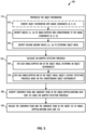
- FIG. 5 shows, in flow chart form, an example process 500 for performing peak detection using object information, according to one embodiment.
- the process 500 can be used to implement the peak detection step 430 of process 400 shown in FIG. 4 .
- the process 500 is described herein with reference to the radar system 100 shown in FIG. 1 and the diagrams 600, 630, and 650 shown in FIG. 6 .
- the process 500 is described herein as being performed by the signal processor 175 in the MCPU 110 executing instructions stored in storage 185 of the radar system 100, but can be performed by any appropriate processing unit executing instructions stored in any appropriate non-transitory computer-readable medium.
- the steps of process 500 are shown in a particular order in FIG. 5 , but the steps of process 500 may be performed in a different order and/or some steps may be performed simultaneously.
- One or more steps of process 500 can be optional, and process 500 can include additional steps.
- Step 510 the process begins at step 510, at which signal processor 175 preprocesses the object information.
- Step 510 includes an optional step 520 and steps 530 and 540.
- the signal processor 175 converts the object information into radar coordinates representative of the range R, Doppler D, and azimuth ⁇ .
- the object information is presented in Cartesian coordinates and includes position and velocity information for each object included in the object information. That is, the object information includes state information x cart for each object.
- the state information x cart for a particular object in Cartesian coordinates can be represented as: x cart ⁇ p x p y v x v y where ( p x , p y ) represents the position of the particular object in Cartesian coordinates and ( v x , v y ) represents the velocity of the particular object in Cartesian coordinates.
- the state information x cart for a particular object is represented by a probability distribution p ( x ) in the object information.
- a Gaussian distribution is used herein, any appropriate probability distribution can be used.
- x radar h ( x cart ) .
- H is the Jacobian matrix of the nonlinear transform h ( ⁇ cart )
- N is the sensor covariance matrix representative of the measurement noise of the radar system 100
- ⁇ r 2 represents the noise variance for the range measurement
- ⁇ d 2 represents the noise variance for the Doppler measurement
- ⁇ ⁇ 2 represents the noise variance for the azimuth measurement.
- the uncertainty of the state estimate p ( x cart ) of the object in Cartesian coordinates is propagated to the state estimate p ( x radar ) of the object in radar coordinates by the linear approximation of h ( ⁇ ) around the point ⁇ cart , and the measurement noise is considered.
- the mean and uncertainties refer to a center of the tracked object.
- the extent of the object is also estimated, such that the uncertainty of the state estimate p ( x ) also captures the extent of the object. That is, the uncertainty of the state estimate p ( x ) can also represent the uncertainty regarding the number of range bins the object occupies.
- Optional step 520 can be omitted for object information already in radar coordinates.
- the signal processor 175 identifies the indices (Ir, Id) of range-Doppler bins corresponding to the radar coordinates (R, D, ⁇ ). That is, for each object included in the object information, the signal processor 175 identifies the range bin index Ir and the Doppler bin index Id corresponding to the determined radar coordinates of the object.
- the signal processor 175 identifies regions around the indices (Ir, Id) to determine object areas. For example, the signal processor 175 determines regions 260, 270, and 280 in the diagram 250.
- the number n r of range bins and the number n d of Doppler bins around the indices (Ir, Id) can be chosen based on the covariance matrix P radar .
- the number n r of range bins and the number n d of Doppler bins are determined by dividing the square root of the first diagonal element of the covariance matrix P radar by the range resolution of the radar system 100 and dividing the square root of the second diagonal element of the covariance matrix P radar by the Doppler resolution of the radar system 100.
- the number n r of range bins can be a fixed value, to reduce the computational complexity.
- the number n r of range bins can set equal to five, such that the tracked object areas include range bins having the indices [ i r - 2, i r - 1, i r , i r + 1 , i r + 2 ].
- the signal processor 175 calculates an adapted detection threshold.
- Step 550 includes step 560 and 570.
- the signal processor 175 determines an object probability density for each range-Doppler bin in the object areas.
- the bin probabilities Pr object [ j ] are the probabilities that the center of an object is in the particular Doppler bin j and can be calculated using a cumulative distribution function of the Gaussian distribution or other numerical approximations.
- w noise is a weight associated with the noise distribution
- a number M of objects are included in the object information
- w object m is a weight associated with the object distribution of a particular object m.
- the weights w noise and w object m are nonnegative and sum to one.
- the particular values of the weights w noise and w object m can be chosen based on the particular implementation. For example, w noise and the sum of w object m can be set equal to fixed values, and the fixed value for the sum of w object m is divided equally between the weights w object m of the M objects in the object information, such that the likelihood of each object is the same. In other implementations, the fixed value for the sum of w object m can be divided between the weights w object m of the M objects in the object information to reflect the relative existence probability of the objects, such that objects with a higher confidence in existence based on prior measurements are weighted more heavily than objects with a lower confidence in existence.
- the weights w noise and w object can be calculated adaptively, for example based on the existence probability of a particular object, the SNR of a particular object, and the like. For example, an object with a greater than 50% existence probability can result in w object being greater than w noise , while an object with a less than 50% existence probability can result in w object being less than w noise .
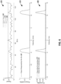
- diagram 600 shown in FIG. 6 represents the object bin probabilities Pr object [ j ] 610 and the noise bin probabilities Pr noise [ j ] 620 over velocity.
- the radar system 100 implements a Doppler-division multiplexing scheme, with the result that a single object is represented at two velocities-in this example, at approximately negative four meters per second (m/s) and at approximately eleven m/s-which are disambiguated by a Doppler disambiguation process.
- a negative velocity is indicative of an object moving towards the radar system 100
- a positive velocity is indicative of an object moving away from the radar system 100.
- the noise bin probabilities Pr noise [ j ] 620 are constant across velocity to reflect the uniform noise distribution.
- the object bin probabilities Pr object [ j ] 610 include peaks at approximately negative four m/s and at approximately eleven m/s, which indicates that the contribution of a radar reflection off the object to the radar signal is much greater than the noise contribution at those velocities.
- the object responsibility per bin R [ object ] [ j ] can be a number between 0 and 1, such that multiplying by 100 gives the percentage-wise contribution of the radar reflections off the tracked object to the total measured radar signal at a particular Doppler bin j.
- the diagram 630 shown in FIG. 6 shows the object responsibility per bin R [ object ] [ j ] 640 for the object bin probabilities Pr object [ j ] 610 and the noise bin probabilities Pr noise [ j ] 620 in diagram 600.
- the contribution of the object bin probabilities Pr object [ j ] 610 relative to the contribution of the noise bin Pr noise [ j ] 620 to the total probability distribution Pr total [ j ] is much higher at the velocities approximately negative four m/s and at approximately eleven m/s than at other velocities.
- the signal processor 175 adjusts a default detection threshold for each range-Doppler bin in the tracked object areas based on the corresponding object responsibility.
- the default detection threshold value Thr default can be lowered by an amount based on the contribution from an object to that particular Doppler bin.
- the maximum permissible decrease a can be chosen based on an SNR characteristic of the radar system 100, an application-specific balance between false alarms and the probability of detection, and the like.
- the radar signal 660 illustrates the radar signal 660, the default detection threshold value Thr default 670, and the adapted detection threshold Thr adapted 680.
- the default detection threshold value Thr default 670 and the a value of the adapted detection threshold Thr adapted 680 are equal.
- the adapted detection threshold Thr adapted 680 has a lower value than the default detection threshold value Thr default 670 based on the object responsibility per bin R [ object ] [ j ] 640 shown in diagram 630.
- the value of the adapted detection threshold Thr adapted 680 is slightly lower than the default detection threshold value Thr default 670, and at a velocity of approximately negative four m/s, the value of the adapted detection threshold Thr adapted 680 is much lower than the default detection threshold value Thr default 670.
- the greater difference between the default detection threshold value Thr default 670 and the value of the adapted detection threshold Thr adapted 680 at negative four m/s relative to negative five m/s reflects the greater object responsibility per bin R [ object ] [ j ] 640 at negative four m/s compared to negative five m/s.
- the signal processor 175 identifies confirmed peaks and candidate peaks in the range-Doppler-antenna data cube 425 using the adapted detection threshold calculated at step 550.
- confirmed peaks are peaks detected outside the object areas in which the adapted detection threshold has a value equal to the default detection threshold.
- Candidate peaks are peaks detected within the object areas in which the adapted detection threshold has a value less than the default detection threshold. For example in diagram 250 shown in FIG. 2 , the points detected with adjusted detection threshold are considered candidate peaks, while the points detected with a constant detection threshold are considered confirmed peaks.
- Candidate peaks can be filtered at step 450 of process 400 as described previously herein, to prevent the introduction of false positives into the point cloud 455.
- the signal processor 175 includes the confirmed peaks and the candidate peaks in the subset 435 of the range-Doppler-antenna data cube 425.
- FIG. 7 shows, in flow chart form, an example process 700 for filtering candidate peaks, according to one embodiment.
- the process 700 can be used to implement the candidate peak filtering step 450 of process 400 shown in FIG. 4 .
- the process 700 is described herein with reference to the radar system 100 shown in FIG. 1 .
- the process 700 is described herein as being performed by the signal processor 175 in the MCPU 110 executing instructions stored in storage 185 of the radar system 100, but can be performed by any appropriate processing unit executing instructions stored in any appropriate non-transitory computer-readable medium.
- the steps of process 700 are shown in a particular order in FIG. 7 , but the steps of process 700 may be performed in a different order and/or some steps may be performed simultaneously.
- One or more steps of process 700 can be optional, and process 700 can include additional steps.
- the process begins at step 705, at which signal processor 175 determines a signal strength for a candidate peak.
- the signal processor 175 determines whether the determined signal strength satisfies a SNR criterion.
- the SNR criterion can be a minimum SNR such that the signal processor 175 determines whether the determined signal strength is greater than the minimum SNR.
- the signal processor 175 discards the candidate peak at step 715. That is, the candidate peak is not sufficiently distinct from noise in the radar signal, and would introduce clutter if included in the point cloud 455.
- the signal processor 175 In response to determining that the signal strength satisfies the SNR criterion, the signal processor 175 includes the candidate peak in a subset at step 720. The signal processor 175 then determines whether there are any remaining candidate peaks at step 725. In response to determining that there are remaining candidate peaks, the signal processor 175 returns to step 705 to analyze the next candidate peak.
- the signal processor 175 proceeds to step 730 and determines a similarity metric between characteristics of the candidate peak and the corresponding tracked object in the prior tracked object information. For example, the signal processor 175 can determine an L1 norm between the value of a characteristic of the candidate peak and the value of the characteristic of the corresponding tracked object.
- the characteristic of the candidate peak and the corresponding tracked object can be a Doppler value 735, an azimuth 740, an elevation 745, and a range 750.
- the signal processor 175 determines similarity metrics between more than one characteristic. For example, the signal processor 175 determines a first similarity metric for the Doppler value 735 and a second similarity metric for the azimuth 740.
- the radar system 100 has a low accuracy and/or resolution for the elevation 745, such that the elevation 745 is not a useful characteristic on which to filter the candidate peaks and the signal processor 175 omits the elevation 745 from consideration.
- the range 750 is already similar between the candidate peak and the corresponding tracked object because the candidate peak is determined from the reduced detection threshold in the tracked object areas.
- the signal processor 175 omits the range 750 from consideration to reduce the computational complexity.
- the signal processor 175 determines whether the one or more similarity metrics satisfy a criterion, such as a maximum difference between the characteristic of the candidate peak and the corresponding tracked object. In response to the similarity metric not satisfying the criterion-for example, in response to the characteristic of the candidate peak and the corresponding tracked object exceeding the maximum difference-the signal processor 175 discards the candidate peak at step 760. In response to the similarity metric satisfying the criterion-for example, in response to the characteristic of the candidate peak and the corresponding tracked object being within the maximum difference-the signal processor 175 includes the candidate peak in the point cloud 455 at step 765. The signal processor 175 then determines whether there are any remaining candidate peaks in the subset at step 770. In response to determining that there are remaining candidate peaks, the signal processor 175 returns to step 730 to analyze the next candidate peak. In response to determining that there are no remaining candidate peaks in the subset, the signal processor 175 outputs the point cloud 455.
- a criterion such as a maximum
- the steps of filtering process 700 can be interspersed among the steps of process 400 to reduce the number of candidate peaks for which the steps of process 400 are completed.
- steps 705-725 can be performed immediately after the candidate peaks are identified at step 430 to filter out candidate peaks based on the corresponding signal strength.
- the steps 730-770 can be performed for the range 750 immediately after the candidate peaks are identified at step 430 to filter out candidate peaks based on the corresponding range.
- the steps 730-770 can be performed for the disambiguated Doppler 735 after the Doppler disambiguation process is performed, reducing the number of candidate peaks for which the angle of arrival is calculated.
- the disclosed techniques for adapting a peak detection threshold based on prior tracked object information reduce the number of false negatives by lowering the detection threshold in regions around tracked objects included in the prior tracked object information, thus increasing the detection sensitivity locally.
- Strategic filtering of the candidate peaks reduces the number of false positives and clutter introduced into the resulting point cloud by the lower detection threshold.
- Strategic filtering also reduces the number of candidate peaks for which additional calculations are performed, thereby reducing the computational cost of the additional peaks identified by the lower detection threshold.
- the adapted detection threshold enables the resulting point cloud to better represent extended objects that occupy more than a single range bin.
- Couple may cover connections, communications, or signal paths that enable a functional relationship consistent with this description, including intermediate or intervening components that do not alter the functional relationship.
- a device that is "configured to" perform a task or function may be configured by programming or hardwiring, for example, at a time of manufacturing by a manufacturer and/or may be configurable or reconfigurable by a user after manufacturing. The configuring may be done through firmware and/or software, construction and/or layout of hardware components and connections, or any combination thereof.
- node "pin”, and “lead” are used interchangeably.
- a circuit or device described herein as including certain components may be adapted to be coupled to those components instead, to form the described circuitry or device.
- a system includes at least one processor and at least one non-transitory computer-readable medium storing machine instructions.
- the machine instructions when executed by the at least one processor, cause the processor to perform a first FFT on received radar data to obtain a range-antenna data array and to perform a second FFT on the range-antenna data array to obtain a range-Doppler-antenna data cube.
- the processor performs peak detection on the range-Doppler-antenna data cube based on object information to obtain a subset of the range-Doppler-antenna data cube.
- the subset of the range-Doppler-antenna data cube includes confirmed peaks and candidate peaks.
- the processor performs angle of arrival calculations for the subset of the range-Doppler-antenna data cube and filters candidate peaks in the subset of the range-Doppler-antenna data cube to obtain a point cloud representative of an environment.
- the confirmed peaks are detected based on a default threshold value, and the candidate peaks are detected based on at least one adapted threshold value.
- the at least one adapted threshold value is determined based on the object information.
- the machine instructions to perform peak detection on the range-Doppler-antenna data cube include machine instructions to preprocess the object information to identify at least one object area and calculate an adapted detection threshold.
- the adapted detection threshold is equal to the default threshold value outside the at least one object area and equal to the at least one adapted threshold value within the at least one object area.
- the processor then identifies confirmed and candidate peaks in the range-Doppler-antenna data cube using the adapted detection threshold.
- the machine instructions to preprocess the object information include machine instructions to, for each tracked object in the object information, convert an object location into radar coordinates and identify indices of range-Doppler bins corresponding to the radar coordinates. The processor then determines regions around the identified indices to obtain the at least one object area.
- the machine instructions to calculate the adapted detection threshold include machine instructions to, for each range-Doppler bin in the at least one object area, determine an object responsibility and adjust the default threshold value based on the corresponding object responsibility to obtain the adapted threshold value.
- the machine instructions to filter candidate peaks include machine instructions to, for each candidate peak, determine a signal strength of the candidate peak and determine whether the signal strength satisfies a first criterion. In response to the signal strength not satisfying the first criterion, the processor discards the candidate peak. In response to the signal strength satisfying the first criterion, the processor includes the candidate peak in a subset.
- the machine instructions to filter candidate peaks further include machine instructions to, for each candidate peak in the subset, determine a similarity metric between a characteristic of the candidate peak and a corresponding characteristic of a corresponding tracked object in the object information and determine whether the similarity metric satisfies a second criterion.
- the processor discards the candidate peak.
- the processor includes the candidate peak in the point cloud.
- the characteristic of the candidate peak and the corresponding characteristic of the corresponding tracked object in the object information includes at least one of a range, a velocity, an azimuth, and an elevation.
- a non-transitory computer-readable medium stores machine instructions which, when executed by at least one processor, cause the processor to perform a first FFT on received radar data to obtain a range-antenna data array and to perform a second FFT on the range-antenna data array to obtain a range-Doppler-antenna data cube.
- the machine instructions cause the processor to perform peak detection on the range-Doppler-antenna data cube based on object information to obtain a subset of the range-Doppler-antenna data cube.
- the subset of the range-Doppler-antenna data cube includes confirmed peaks and candidate peaks.
- the machine instructions cause the processor to perform angle of arrival calculations for the subset of the range-Doppler-antenna data cube and filter candidate peaks in the subset of the range-Doppler-antenna data cube to obtain a point cloud representative of an environment.
- the confirmed peaks are detected based on a default threshold value, and the candidate peaks are detected based on at least one adapted threshold value.
- the at least one adapted threshold value is determined based on the object information.
- the machine instructions to perform peak detection on the range-Doppler-antenna data cube include machine instructions to preprocess the object information to identify at least one object area and calculate an adapted detection threshold.
- the adapted detection threshold is equal to the default threshold value outside the at least one object area and equal to the at least one adapted threshold value within the at least one object area.
- the machine instructions then cause the processor to identify confirmed and candidate peaks in the range-Doppler-antenna data cube using the adapted detection threshold.
- the machine instructions to preprocess the object information include machine instructions to, for each tracked object in the object information, convert an object location into radar coordinates and identify indices of range-Doppler bins corresponding to the radar coordinates.
- the machine instructions cause the processor to determine regions around the identified indices to obtain the at least one object area.
- the machine instructions to calculate the adapted detection threshold include machine instructions to, for each range-Doppler bin in the at least one object area, determine an object responsibility and adjust the default threshold value based on the corresponding object responsibility to obtain the adapted threshold value.
- the machine instructions to filter candidate peaks include machine instructions to, for each candidate peak, determine a signal strength of the candidate peak and determine whether the signal strength satisfies a first criterion. In response to the signal strength not satisfying the first criterion, the machine instructions cause the processor to discard the candidate peak. In response to the signal strength satisfying the first criterion, the machine instructions cause the processor to include the candidate peak in a subset.
- the machine instructions to filter candidate peaks further include machine instructions to, for each candidate peak in the subset, determine a similarity metric between a characteristic of the candidate peak and a corresponding characteristic of a corresponding tracked object in the object information and determine whether the similarity metric satisfies a second criterion.
- the machine instructions In response to the similarity metric not satisfying the second criterion, the machine instructions cause the processor to discard the candidate peak. In response to the similarity metric satisfying the second criterion, the machine instructions cause the processor to include the candidate peak in the point cloud.
- the characteristic of the candidate peak and the corresponding characteristic of the corresponding tracked object in the object information includes at least one of a range, a velocity, an azimuth, and an elevation.
- a method includes performing a first FFT on received radar data to obtain a range-antenna data array and performing a second FFT on the range-antenna data array to obtain a range-Doppler-antenna data cube.
- Peak detection is performed on the range-Doppler-antenna data cube based on object information to obtain a subset of the range-Doppler-antenna data cube.
- the subset of the range-Doppler-antenna data cube includes confirmed peaks and candidate peaks.
- Angle of arrival calculations are performed for the subset of the range-Doppler-antenna data cube and candidate peaks in the subset of the range-Doppler-antenna data cube are filtered to obtain a point cloud representative of an environment.
- the confirmed peaks are detected based on a default threshold value, and the candidate peaks are detected based on at least one adapted threshold value.
- the at least one adapted threshold value is determined based on the object information.
- performing peak detection on the range-Doppler-antenna data cube includes preprocessing the object information to identify at least one object area and calculating an adapted detection threshold.
- the adapted detection threshold is equal to the default threshold value outside the at least one object area and equal to the at least one adapted threshold value within the at least one object area. Confirmed and candidate peaks in the range-Doppler-antenna data cube are identified using the adapted detection threshold.
- preprocessing the object information includes converting, for each tracked object in the object information, an object location into radar coordinates and identifying, for each tracked object in the object information, indices of range-Doppler bins corresponding to the radar coordinates. Regions around the identified indices are determined to obtain the at least one object area.
- calculating the adapted detection threshold includes determining, for each range-Doppler bin in the at least one object area, an object responsibility and adjusting, for each range-Doppler bin in the at least one object area, the default threshold value based on the corresponding object responsibility to obtain the adapted threshold value.
- filtering candidate peaks includes determining, for each candidate peak, a signal strength of the candidate peak and whether the signal strength satisfies a first criterion. In response to the signal strength not satisfying the first criterion, the candidate peak is discarded. In response to the signal strength satisfying the first criterion, the candidate peak is included in a subset. Filtering candidate peaks further includes determining, for each candidate peak in the subset, a similarity metric between a characteristic of the candidate peak and a corresponding characteristic of a corresponding tracked object in the object information and determining whether the similarity metric satisfies a second criterion. In response to the similarity metric not satisfying the second criterion, the candidate peak is discarded.
- the candidate peak is included in the point cloud.
- the characteristic of the candidate peak and the corresponding characteristic of the corresponding tracked object in the object information includes at least one of a range, a velocity, an azimuth, and an elevation.
Landscapes
- Engineering & Computer Science (AREA)
- Radar, Positioning & Navigation (AREA)
- Remote Sensing (AREA)
- Physics & Mathematics (AREA)
- General Physics & Mathematics (AREA)
- Computer Networks & Wireless Communication (AREA)
- Electromagnetism (AREA)
- Radar Systems Or Details Thereof (AREA)
Applications Claiming Priority (1)
| Application Number | Priority Date | Filing Date | Title |
|---|---|---|---|
| US18/365,350 US12585011B2 (en) | 2023-08-04 | 2023-08-04 | Radar detection using prior tracked object information |
Publications (1)
| Publication Number | Publication Date |
|---|---|
| EP4509864A1 true EP4509864A1 (fr) | 2025-02-19 |
Family
ID=91968906
Family Applications (1)
| Application Number | Title | Priority Date | Filing Date |
|---|---|---|---|
| EP24190666.8A Pending EP4509864A1 (fr) | 2023-08-04 | 2024-07-24 | Détection radar améliorée utilisant des informations d'objet suivies antérieures |
Country Status (3)
| Country | Link |
|---|---|
| US (1) | US12585011B2 (fr) |
| EP (1) | EP4509864A1 (fr) |
| CN (1) | CN119439090A (fr) |
Families Citing this family (1)
| Publication number | Priority date | Publication date | Assignee | Title |
|---|---|---|---|---|
| JP7470729B2 (ja) * | 2022-03-28 | 2024-04-18 | アンリツ株式会社 | 移動端末試験装置とその移動端末の位置補正方法 |
Citations (2)
| Publication number | Priority date | Publication date | Assignee | Title |
|---|---|---|---|---|
| US20190146081A1 (en) * | 2017-11-16 | 2019-05-16 | GM Global Technology Operations LLC | Vehicle radar control |
| US20200341134A1 (en) * | 2019-04-26 | 2020-10-29 | Infineon Technologies Ag | Radar device and method for detecting radar targets |
Family Cites Families (64)
| Publication number | Priority date | Publication date | Assignee | Title |
|---|---|---|---|---|
| US5465095A (en) * | 1994-08-05 | 1995-11-07 | The United States Of America As Represented By The Secretary Of The Air Force | Time efficient method for processing adaptive target detection thresholds in doppler radar systems |
| BR0308287A (pt) * | 2002-03-13 | 2005-01-11 | Raytheon Canada Ltd | Sistema e método de detecção adaptáveis |
| US20080018523A1 (en) * | 2006-07-18 | 2008-01-24 | Kelly Jr Thomas M | Method and system for radar processing |
| JP2014025916A (ja) * | 2012-06-21 | 2014-02-06 | Furuno Electric Co Ltd | 物標探知装置、およびエコー信号処理方法 |
| DE102012024999A1 (de) * | 2012-12-19 | 2014-06-26 | Valeo Schalter Und Sensoren Gmbh | Verfahren zum Einstellen einer Detektionsschwelle für ein Empfangssignal eines Frequenzmodulations-Dauerstrich-Radarsensors eines Kraftfahrzeugs abhängig vom Rauschpegel, Radarsensor und Kraftfahrzeug |
| JP5972402B2 (ja) * | 2013-02-01 | 2016-08-17 | 三菱電機株式会社 | レーダ装置 |
| US9594159B2 (en) * | 2013-07-15 | 2017-03-14 | Texas Instruments Incorporated | 2-D object detection in radar applications |
| US10054680B2 (en) * | 2014-07-09 | 2018-08-21 | Bae Systems Information And Electronic Systems Integration Inc. | Radar detection of endo-clutter high-value targets using tracker feedback |
| US10627480B2 (en) * | 2014-07-17 | 2020-04-21 | Texas Instruments Incorporated | Distributed radar signal processing in a radar system |
| US9470777B2 (en) * | 2014-09-19 | 2016-10-18 | Delphi Technologies, Inc. | Radar system for automated vehicle with phase change based target catagorization |
| US10514454B1 (en) * | 2014-10-24 | 2019-12-24 | The United States of America, as represented by the Administrator of the Federal Aviation Administration | Techniques for mitigating the effects of complex structures on radar systems |
| JP6567832B2 (ja) * | 2015-01-29 | 2019-08-28 | 日本電産株式会社 | レーダシステム、レーダ信号処理装置、車両走行制御装置および方法、ならびにコンピュータプログラム |
| WO2017218876A1 (fr) * | 2016-06-17 | 2017-12-21 | Quovard Management Llc | Réseau d'antennes radar |
| US10775489B2 (en) * | 2016-12-15 | 2020-09-15 | Texas Instruments Incorporated | Maximum measurable velocity in frequency modulated continuous wave (FMCW) radar |
| GB2559157A (en) * | 2017-01-27 | 2018-08-01 | Ucl Business Plc | Apparatus, method and system for alignment of 3D datasets |
| EP3370365B1 (fr) * | 2017-03-02 | 2020-07-01 | Nxp B.V. | Module de traitement et procédé associé |
| US11047970B2 (en) * | 2017-05-05 | 2021-06-29 | Texas Instruments Incorporated | Multi-mode radar systems, signal processing methods and configuration methods using pushing windows |
| US11005179B2 (en) * | 2017-06-05 | 2021-05-11 | Metawave Corporation | Feed structure for a metamaterial antenna system |
| US20190096866A1 (en) * | 2017-09-26 | 2019-03-28 | Powertech Technology Inc. | Semiconductor package and manufacturing method thereof |
| KR102071457B1 (ko) * | 2018-03-13 | 2020-01-30 | 삼성전자주식회사 | 팬-아웃 반도체 패키지 |
| DE102018106858A1 (de) * | 2018-03-22 | 2019-09-26 | Infineon Technologies Ag | Fmcw-radar mit zusätzlicher am zur störungsdetektion |
| DE102018208366B3 (de) * | 2018-05-28 | 2019-11-28 | Deutsches Zentrum für Luft- und Raumfahrt e.V. | Synthetik-Apertur-Radarverfahren und Synthetik-Apertur-Radarvorrichtung |
| US10962637B2 (en) * | 2018-06-25 | 2021-03-30 | Texas Instruments Incorporated | Radar data processing using neural network classifier and confidence metrics |
| DE102018116378A1 (de) * | 2018-07-06 | 2020-01-09 | Valeo Schalter Und Sensoren Gmbh | Verfahren zur Ermittlung von wenigstens einer Objektinformation wenigstens eines Zielobjekts, das mit einem Radarsystem insbesondere eines Fahrzeugs erfasst wird, Radarsystem und Fahrerassistenzsystem |
| KR102532205B1 (ko) * | 2018-07-09 | 2023-05-12 | 삼성전자 주식회사 | 반도체 칩 및 그 반도체 칩을 포함한 반도체 패키지 |
| EP3620810B1 (fr) * | 2018-09-05 | 2022-07-13 | Nxp B.V. | Détection d'interférences radar |
| US11073608B2 (en) * | 2018-10-11 | 2021-07-27 | Raytheon Company | Resolving radar angle ambiguities using a multiple hypothesis tracker |
| US10996313B2 (en) * | 2018-10-29 | 2021-05-04 | Texas Instruments Incorporated | FMCW radar reduced power mode |
| DE102018127947B3 (de) * | 2018-11-08 | 2020-03-19 | Infineon Technologies Ag | Mimo fmcw radarsystem |
| DE102019106529B4 (de) * | 2019-03-14 | 2024-10-31 | Infineon Technologies Ag | Fmcw radar mit störsignalunterdrückung mittels künstlichem neuronalen netz |
| US11782148B2 (en) * | 2019-03-25 | 2023-10-10 | Texas Instruments Incorporated | Radar system |
| KR102661671B1 (ko) * | 2019-07-25 | 2024-04-29 | 삼성전자주식회사 | 적층된 반도체 칩들을 포함하는 반도체 패키지 |
| DE102019216017A1 (de) * | 2019-10-17 | 2021-04-22 | Robert Bosch Gmbh | Verfahren und Vorrichtung zur Verarbeitung einer Doppler-Range-Matrix und Radarsystem |
| DE102019133977A1 (de) * | 2019-12-11 | 2021-06-17 | Valeo Schalter Und Sensoren Gmbh | Verfahren zur Ermittlung von wenigstens einer Objektinformation wenigstens eines Objektes, das mit einem Radarsystem erfasst wird und Radarsystem |
| KR102749279B1 (ko) * | 2020-02-27 | 2025-01-02 | 삼성전자주식회사 | 반도체 패키지 |
| WO2021177956A1 (fr) * | 2020-03-04 | 2021-09-10 | Google Llc | Système radar basé sur un dispositif intelligent réalisant une détection à portée proximale |
| EP3939005B1 (fr) * | 2020-05-15 | 2024-10-23 | Baidu.com Times Technology (Beijing) Co., Ltd. | Détecteur pour une fusion de nuages de points |
| EP3923023A3 (fr) * | 2020-05-20 | 2022-03-09 | Infineon Technologies AG | Traitement de signaux radar |
| US12013484B2 (en) * | 2020-05-20 | 2024-06-18 | Infineon Technologies Ag | Radar receiving system and method for compensating a phase error between radar receiving circuits |
| US11982732B2 (en) * | 2020-06-09 | 2024-05-14 | Samsung Electronics Co., Ltd. | Method and apparatus for processing radar signal by correcting phase distortion |
| US11047963B1 (en) * | 2020-08-21 | 2021-06-29 | Aeva, Inc. | Selective sub-band processing for angular resolution and detection sensitivity in a LIDAR system |
| DE102020127177A1 (de) * | 2020-10-15 | 2022-04-21 | Infineon Technologies Ag | Radarvorrichtung und verfahren zum detektieren von radarzielen |
| KR102907016B1 (ko) * | 2020-10-29 | 2026-01-05 | 삼성전자주식회사 | 반도체 패키지 |
| WO2022139783A1 (fr) * | 2020-12-21 | 2022-06-30 | Intel Corporation | Radar d'imagerie haut de gamme |
| WO2022165211A1 (fr) * | 2021-01-29 | 2022-08-04 | Indie Semiconductor, Inc. | Procédé de détection d'objets dans des signaux radar de qualité automobile |
| KR102939567B1 (ko) * | 2021-03-09 | 2026-03-13 | 삼성전자주식회사 | 반도체 패키지 |
| DE102021110060A1 (de) * | 2021-04-21 | 2022-10-27 | Infineon Technologies Ag | Systeme, vorrichtungen und verfahren zur radardetektion |
| US12196880B2 (en) * | 2021-04-28 | 2025-01-14 | The United States Of America As Represented By The Secretary Of The Army | Method and apparatus for detecting and characterizing pulse sequences |
| KR20230052367A (ko) * | 2021-10-12 | 2023-04-20 | 삼성전자주식회사 | 반도체 패키지 및 이의 제조 방법 |
| US20230138813A1 (en) * | 2021-11-02 | 2023-05-04 | Samsung Electronics Co., Ltd. | Semiconductor package |
| KR20230063426A (ko) * | 2021-11-02 | 2023-05-09 | 삼성전자주식회사 | 반도체 패키지 및 그 제조방법 |
| KR20230064405A (ko) * | 2021-11-03 | 2023-05-10 | 삼성전자주식회사 | 반도체 패키지 |
| KR20230167163A (ko) * | 2022-05-30 | 2023-12-08 | 삼성전자주식회사 | 반도체 패키지 및 제조방법 |
| US12270930B1 (en) * | 2022-07-12 | 2025-04-08 | Spartan Radar, Inc. | Methods and systems for processing radar signals |
| KR20240015225A (ko) * | 2022-07-26 | 2024-02-05 | 삼성전자주식회사 | 반도체 패키지 |
| KR20240037739A (ko) * | 2022-09-15 | 2024-03-22 | 삼성전자주식회사 | 반도체 패키지 |
| US12372639B2 (en) * | 2022-09-16 | 2025-07-29 | GM Global Technology Operations LLC | Doppler radar resolution based on inertial measurement unit of vehicle |
| KR20240085948A (ko) * | 2022-12-08 | 2024-06-18 | 삼성전자주식회사 | 관통 전극을 갖는 반도체 칩을 포함하는 반도체 패키지 |
| KR20240088451A (ko) * | 2022-12-13 | 2024-06-20 | 삼성전자주식회사 | 반도체 칩 및 이를 포함하는 반도체 패키지 |
| EP4414739B1 (fr) * | 2023-02-08 | 2025-03-26 | Axis AB | Procédé, dispositif et système pour identifier qu'une première unité radar est soumise à une interférence à partir d'une seconde unité radar |
| US12571880B2 (en) * | 2023-03-14 | 2026-03-10 | Infineon Technologies Ag | Hardware boundary checking for radar |
| US20240353529A1 (en) * | 2023-04-21 | 2024-10-24 | Infineon Technologies Ag | Integration of virtual channels from doppler division multiplex (ddm) fmcw radar signal |
| US12461196B2 (en) * | 2023-05-17 | 2025-11-04 | Nxp B.V. | Method and apparatus for processing joint multiple chirp sequences |
| US12386038B2 (en) * | 2023-06-07 | 2025-08-12 | Aptiv Technologies AG | Radar system using a machine-learned model for identifying a number of objects |
-
2023
- 2023-08-04 US US18/365,350 patent/US12585011B2/en active Active
-
2024
- 2024-07-24 EP EP24190666.8A patent/EP4509864A1/fr active Pending
- 2024-08-05 CN CN202411063006.3A patent/CN119439090A/zh active Pending
Patent Citations (2)
| Publication number | Priority date | Publication date | Assignee | Title |
|---|---|---|---|---|
| US20190146081A1 (en) * | 2017-11-16 | 2019-05-16 | GM Global Technology Operations LLC | Vehicle radar control |
| US20200341134A1 (en) * | 2019-04-26 | 2020-10-29 | Infineon Technologies Ag | Radar device and method for detecting radar targets |
Also Published As
| Publication number | Publication date |
|---|---|
| CN119439090A (zh) | 2025-02-14 |
| US20250044439A1 (en) | 2025-02-06 |
| US12585011B2 (en) | 2026-03-24 |
Similar Documents
| Publication | Publication Date | Title |
|---|---|---|
| CN112630768B (zh) | 一种改进调频连续波雷达目标检测的降噪方法 | |
| US11249180B2 (en) | Method and device for ascertaining transverse relative velocity components of radar targets | |
| CN107076836B (zh) | 用于对机动车辆周围区域中的对象分类的方法、驾驶员辅助系统和机动车辆 | |
| CN110058239B (zh) | 一种车载毫米波雷达装置及目标探测方法 | |
| TWI504916B (zh) | 調頻連續波雷達感測系統之信號處理方法及信號處理裝置 | |
| WO2021247427A1 (fr) | Groupement dans une imagerie automobile | |
| JP7173735B2 (ja) | レーダ装置及び信号処理方法 | |
| US11709246B2 (en) | Radar apparatus | |
| US20190346548A1 (en) | Filtering to address range walk effect in range-doppler map | |
| EP3483630B1 (fr) | Détection de configuration de place de stationnement basée sur des modèles répétitifs | |
| US11300655B2 (en) | Object detection using radar | |
| EP4509864A1 (fr) | Détection radar améliorée utilisant des informations d'objet suivies antérieures | |
| US20240369681A1 (en) | Method for Calibration of a Radar Sensor | |
| CN114859337B (zh) | 数据处理方法、装置、电子设备、计算机存储介质 | |
| US20230384440A1 (en) | Super-Resolution Based on Iterative Multiple-Source Angle-of-Arrival Estimation | |
| CN118584469B (zh) | 一种基于置信度加权的毫米波雷达远距离目标测角方法 | |
| US20220381901A1 (en) | Pre-Processing of Radar Measurement Data for Object Detection | |
| CN120500646A (zh) | 一种占据栅格地图生成方法及装置 | |
| US12372641B2 (en) | Ego velocity estimator for radar systems | |
| US20240280692A1 (en) | Fine-near-range estimation method for automotive radar applications | |
| US12546876B2 (en) | Object sensing method and radar apparatus | |
| EP4492088A1 (fr) | Estimateur de direction d'arrivée assisté par la vitesse ego pour systèmes radar | |
| CN118962616A (zh) | 基于毫米波雷达与相机的目标检测方法、装置、车辆及介质 | |
| CN117111008A (zh) | 基于迭代多源到达角估计的超分辨率 | |
| CN120630135A (zh) | 雷达设备以及雷达处理方法 |
Legal Events
| Date | Code | Title | Description |
|---|---|---|---|
| PUAI | Public reference made under article 153(3) epc to a published international application that has entered the european phase |
Free format text: ORIGINAL CODE: 0009012 |
|
| STAA | Information on the status of an ep patent application or granted ep patent |
Free format text: STATUS: THE APPLICATION HAS BEEN PUBLISHED |
|
| AK | Designated contracting states |
Kind code of ref document: A1 Designated state(s): AL AT BE BG CH CY CZ DE DK EE ES FI FR GB GR HR HU IE IS IT LI LT LU LV MC ME MK MT NL NO PL PT RO RS SE SI SK SM TR |
|
| STAA | Information on the status of an ep patent application or granted ep patent |
Free format text: STATUS: REQUEST FOR EXAMINATION WAS MADE |
|
| 17P | Request for examination filed |
Effective date: 20250819 |