EP4509878A1 - Verfahren und vorrichtung zur verarbeitung einer laserradarpunktwolke - Google Patents
Verfahren und vorrichtung zur verarbeitung einer laserradarpunktwolke Download PDFInfo
- Publication number
- EP4509878A1 EP4509878A1 EP23893155.4A EP23893155A EP4509878A1 EP 4509878 A1 EP4509878 A1 EP 4509878A1 EP 23893155 A EP23893155 A EP 23893155A EP 4509878 A1 EP4509878 A1 EP 4509878A1
- Authority
- EP
- European Patent Office
- Prior art keywords
- point cloud
- gray image
- target
- unit
- units
- Prior art date
- Legal status (The legal status is an assumption and is not a legal conclusion. Google has not performed a legal analysis and makes no representation as to the accuracy of the status listed.)
- Pending
Links
Images





Classifications
-
- G—PHYSICS
- G01—MEASURING; TESTING
- G01S—RADIO DIRECTION-FINDING; RADIO NAVIGATION; DETERMINING DISTANCE OR VELOCITY BY USE OF RADIO WAVES; LOCATING OR PRESENCE-DETECTING BY USE OF THE REFLECTION OR RERADIATION OF RADIO WAVES; ANALOGOUS ARRANGEMENTS USING OTHER WAVES
- G01S7/00—Details of systems according to groups G01S13/00, G01S15/00, G01S17/00
- G01S7/48—Details of systems according to groups G01S13/00, G01S15/00, G01S17/00 of systems according to group G01S17/00
- G01S7/4802—Details of systems according to groups G01S13/00, G01S15/00, G01S17/00 of systems according to group G01S17/00 using analysis of echo signal for target characterisation; Target signature; Target cross-section
-
- G—PHYSICS
- G01—MEASURING; TESTING
- G01S—RADIO DIRECTION-FINDING; RADIO NAVIGATION; DETERMINING DISTANCE OR VELOCITY BY USE OF RADIO WAVES; LOCATING OR PRESENCE-DETECTING BY USE OF THE REFLECTION OR RERADIATION OF RADIO WAVES; ANALOGOUS ARRANGEMENTS USING OTHER WAVES
- G01S13/00—Systems using the reflection or reradiation of radio waves, e.g. radar systems; Analogous systems using reflection or reradiation of waves whose nature or wavelength is irrelevant or unspecified
- G01S13/86—Combinations of radar systems with non-radar systems, e.g. sonar, direction finder
- G01S13/865—Combination of radar systems with lidar systems
-
- G—PHYSICS
- G01—MEASURING; TESTING
- G01S—RADIO DIRECTION-FINDING; RADIO NAVIGATION; DETERMINING DISTANCE OR VELOCITY BY USE OF RADIO WAVES; LOCATING OR PRESENCE-DETECTING BY USE OF THE REFLECTION OR RERADIATION OF RADIO WAVES; ANALOGOUS ARRANGEMENTS USING OTHER WAVES
- G01S13/00—Systems using the reflection or reradiation of radio waves, e.g. radar systems; Analogous systems using reflection or reradiation of waves whose nature or wavelength is irrelevant or unspecified
- G01S13/88—Radar or analogous systems specially adapted for specific applications
- G01S13/89—Radar or analogous systems specially adapted for specific applications for mapping or imaging
-
- G—PHYSICS
- G01—MEASURING; TESTING
- G01S—RADIO DIRECTION-FINDING; RADIO NAVIGATION; DETERMINING DISTANCE OR VELOCITY BY USE OF RADIO WAVES; LOCATING OR PRESENCE-DETECTING BY USE OF THE REFLECTION OR RERADIATION OF RADIO WAVES; ANALOGOUS ARRANGEMENTS USING OTHER WAVES
- G01S17/00—Systems using the reflection or reradiation of electromagnetic waves other than radio waves, e.g. lidar systems
- G01S17/88—Lidar systems specially adapted for specific applications
- G01S17/89—Lidar systems specially adapted for specific applications for mapping or imaging
-
- G—PHYSICS
- G01—MEASURING; TESTING
- G01S—RADIO DIRECTION-FINDING; RADIO NAVIGATION; DETERMINING DISTANCE OR VELOCITY BY USE OF RADIO WAVES; LOCATING OR PRESENCE-DETECTING BY USE OF THE REFLECTION OR RERADIATION OF RADIO WAVES; ANALOGOUS ARRANGEMENTS USING OTHER WAVES
- G01S17/00—Systems using the reflection or reradiation of electromagnetic waves other than radio waves, e.g. lidar systems
- G01S17/88—Lidar systems specially adapted for specific applications
- G01S17/93—Lidar systems specially adapted for specific applications for anti-collision purposes
- G01S17/931—Lidar systems specially adapted for specific applications for anti-collision purposes of land vehicles
-
- G—PHYSICS
- G01—MEASURING; TESTING
- G01S—RADIO DIRECTION-FINDING; RADIO NAVIGATION; DETERMINING DISTANCE OR VELOCITY BY USE OF RADIO WAVES; LOCATING OR PRESENCE-DETECTING BY USE OF THE REFLECTION OR RERADIATION OF RADIO WAVES; ANALOGOUS ARRANGEMENTS USING OTHER WAVES
- G01S7/00—Details of systems according to groups G01S13/00, G01S15/00, G01S17/00
- G01S7/48—Details of systems according to groups G01S13/00, G01S15/00, G01S17/00 of systems according to group G01S17/00
- G01S7/4808—Evaluating distance, position or velocity data
-
- G—PHYSICS
- G06—COMPUTING OR CALCULATING; COUNTING
- G06T—IMAGE DATA PROCESSING OR GENERATION, IN GENERAL
- G06T5/00—Image enhancement or restoration
- G06T5/70—Denoising; Smoothing
-
- G—PHYSICS
- G06—COMPUTING OR CALCULATING; COUNTING
- G06T—IMAGE DATA PROCESSING OR GENERATION, IN GENERAL
- G06T7/00—Image analysis
- G06T7/10—Segmentation; Edge detection
- G06T7/11—Region-based segmentation
-
- G—PHYSICS
- G06—COMPUTING OR CALCULATING; COUNTING
- G06T—IMAGE DATA PROCESSING OR GENERATION, IN GENERAL
- G06T7/00—Image analysis
- G06T7/10—Segmentation; Edge detection
- G06T7/12—Edge-based segmentation
-
- G—PHYSICS
- G06—COMPUTING OR CALCULATING; COUNTING
- G06T—IMAGE DATA PROCESSING OR GENERATION, IN GENERAL
- G06T7/00—Image analysis
- G06T7/10—Segmentation; Edge detection
- G06T7/13—Edge detection
-
- G—PHYSICS
- G06—COMPUTING OR CALCULATING; COUNTING
- G06T—IMAGE DATA PROCESSING OR GENERATION, IN GENERAL
- G06T7/00—Image analysis
- G06T7/50—Depth or shape recovery
- G06T7/55—Depth or shape recovery from multiple images
- G06T7/564—Depth or shape recovery from multiple images from contours
-
- G—PHYSICS
- G06—COMPUTING OR CALCULATING; COUNTING
- G06V—IMAGE OR VIDEO RECOGNITION OR UNDERSTANDING
- G06V10/00—Arrangements for image or video recognition or understanding
- G06V10/70—Arrangements for image or video recognition or understanding using pattern recognition or machine learning
- G06V10/77—Processing image or video features in feature spaces; using data integration or data reduction, e.g. principal component analysis [PCA] or independent component analysis [ICA] or self-organising maps [SOM]; Blind source separation
- G06V10/80—Fusion, i.e. combining data from various sources at the sensor level, preprocessing level, feature extraction level or classification level
- G06V10/806—Fusion, i.e. combining data from various sources at the sensor level, preprocessing level, feature extraction level or classification level of extracted features
-
- G—PHYSICS
- G06—COMPUTING OR CALCULATING; COUNTING
- G06V—IMAGE OR VIDEO RECOGNITION OR UNDERSTANDING
- G06V10/00—Arrangements for image or video recognition or understanding
- G06V10/98—Detection or correction of errors, e.g. by rescanning the pattern or by human intervention; Evaluation of the quality of the acquired patterns
-
- G—PHYSICS
- G06—COMPUTING OR CALCULATING; COUNTING
- G06T—IMAGE DATA PROCESSING OR GENERATION, IN GENERAL
- G06T2207/00—Indexing scheme for image analysis or image enhancement
- G06T2207/10—Image acquisition modality
- G06T2207/10028—Range image; Depth image; 3D point clouds
-
- G—PHYSICS
- G06—COMPUTING OR CALCULATING; COUNTING
- G06T—IMAGE DATA PROCESSING OR GENERATION, IN GENERAL
- G06T2207/00—Indexing scheme for image analysis or image enhancement
- G06T2207/10—Image acquisition modality
- G06T2207/10032—Satellite or aerial image; Remote sensing
- G06T2207/10044—Radar image
-
- G—PHYSICS
- G06—COMPUTING OR CALCULATING; COUNTING
- G06V—IMAGE OR VIDEO RECOGNITION OR UNDERSTANDING
- G06V10/00—Arrangements for image or video recognition or understanding
- G06V10/20—Image preprocessing
- G06V10/26—Segmentation of patterns in the image field; Cutting or merging of image elements to establish the pattern region, e.g. clustering-based techniques; Detection of occlusion
-
- G—PHYSICS
- G06—COMPUTING OR CALCULATING; COUNTING
- G06V—IMAGE OR VIDEO RECOGNITION OR UNDERSTANDING
- G06V20/00—Scenes; Scene-specific elements
- G06V20/50—Context or environment of the image
- G06V20/56—Context or environment of the image exterior to a vehicle by using sensors mounted on the vehicle
Definitions
- This application relates to point cloud processing technologies, and in particular, to a lidar point cloud processing method and apparatus.
- a lidar has become one of the most important manners for detecting data.
- a point cloud generated by the lidar may describe a scene in a 3D form.
- the point cloud may be missing.
- road conditions are complex.
- a high reflective target like a vehicle light, a vehicle license plate, or a road plate may cause a problem of a missing point cloud or point cloud hole.
- point cloud complement becomes a key technology of a key target detection algorithm.
- point cloud complement is implemented based on guidance of a 2D image generated by a camera.
- a series of calibration and registration operations need to be performed, and then feature extraction and fusion are performed on the 2D image and a 3D point cloud, to finally implement point cloud complement. This directly increases algorithm difficulty and reduces target detection accuracy.
- This application provides a lidar point cloud processing method and apparatus, to obtain a high-quality lidar point cloud without performing calibration and registration operations, so as to reduce hardware costs, and improve device utilization.
- this application provides a lidar point cloud processing method, including: obtaining a to-be-processed point cloud and a reference gray image corresponding to a radar field of view, where the to-be-processed point cloud is synthesized by point clouds of a plurality of units, the reference gray image is synthesized by gray images of the plurality of units, a point cloud of a first unit is obtained under laser illumination, a gray image of the first unit is obtained under ambient light illumination, the point cloud of the first unit and the gray image of the first unit are alternately collected by a same sensor, and the first unit is any one of the plurality of units; obtaining a contour of a target based on the reference gray image; and complementing the to-be-processed point cloud based on the contour of the target to obtain a target point cloud.
- the 3D point cloud and the 2D gray image of a same field of view are obtained by using a single sensor in a lidar in a time-division manner, to ensure coordinate consistency between the 3D point cloud and the 2D gray image.
- the gray image may be used as a reference to complement a hole or a missing point in the point cloud, to obtain a high-quality lidar point cloud.
- hardware costs are reduced and device utilization is improved.
- the to-be-processed point cloud is synthesized by the point clouds of the plurality of units, and the reference gray image is synthesized by the gray images of the plurality of units.
- the point cloud may include a plurality of units.
- the unit may be a single point in the point cloud, or the unit may be all points included in a line in the point cloud. For example, pixels corresponding to a complete point cloud of a frame are 576*96. If the unit is a single point, the point cloud includes 576*96 units. If the unit is a line, the point cloud may include 576 units or 96 units. It should be noted that another unit granularity may alternatively be used in embodiments of this application. This is not specifically limited.
- a sensor for example, a photon detector performs time-division collection, and may obtain a 3D point cloud and a 2D gray image of the unit.
- An active imaging (Active Imaging) signal is a point cloud formed based on photons collected by the sensor (for example, the photon detector) under a laser, and the point cloud includes depth information under laser illumination. Therefore, the active imaging signal may refer to the 3D point cloud of the unit, and the 3D point cloud includes spatial location and intensity information of the unit.
- the intensity information may be independently indicated as a 2D gray image. Because the 2D gray image and the 3D point cloud are collected in a same light field, information about the 2D gray image is completely included in the 3D point cloud. However, the 2D gray image also has the same hole or missing point as the 3D point cloud.
- An inactive imaging (Inactive Imaging) signal is an image formed based on photons collected by the sensor (for example, the photon detector) in ambient light, and the image includes intensity information under ambient light illumination. Therefore, the inactive imaging signal may refer to the 2D gray image of the unit.
- the image obtained through measurement by the lidar does not include the depth information but only includes the intensity information of the light because there is no laser.
- the point cloud of the first unit (the first unit is any one of the plurality of units) and the gray image of the first unit are separately collected by a same sensor in collection cycles that alternate with each other.
- the point clouds of the plurality of units may be synthesized into the to-be-processed point cloud, and the gray images of the plurality of units may be synthesized into the reference gray image.
- time-division collection of the single sensor for example, the photon detector
- Hardware costs are reduced, and device utilization can be improved.
- a same sensor alternately collects imaging signals (a point cloud and a gray image) of a same unit in short time, so that the point cloud and the gray image can correspond to a same field of view, to ensure coordinate consistency between the two. In this way, matching efficiency and accuracy between the two can be improved without a need to perform calibration and registration operations.
- the point clouds and the gray images may be obtained unit by unit in a predetermined order (for example, in a left-to-right order or a top-to-bottom order, or in a Z-shaped order, which is not specifically limited); the point clouds of the plurality of units are synthesized to obtain the to-be-processed point cloud; and the gray images of the plurality of units are synthesized to obtain the reference gray image.
- a predetermined order for example, in a left-to-right order or a top-to-bottom order, or in a Z-shaped order, which is not specifically limited
- the point clouds of the plurality of units are synthesized to obtain the to-be-processed point cloud
- the gray images of the plurality of units are synthesized to obtain the reference gray image.
- the synthesized frame data includes the 3D point cloud (namely, the to-be-processed point cloud) synthesized by the point clouds of all the units and the 2D gray image (namely, the reference gray image) synthesized by the gray images of all the units.
- the gray image is obtained by using the sensor in a first collection cycle
- the point cloud is obtained by using the sensor in a second collection cycle.
- the first collection cycle and the second collection cycle alternate with each other, and a laser light is turned off in the first collection cycle, and the laser light is turned on in the second collection cycle.
- the first collection cycle may be a HistTrg active cycle
- the second collection cycle may be a SlotTrg active cycle.
- the two collection cycles alternate with each other, and a sequence of the two collection cycles is not limited.
- the photon detector When the laser is turned on, the photon detector collects the depth information; and when the laser is turned off, the photon detector collects the intensity information of a scene in ambient light, to obtain a point cloud and a gray image of a unit in a time-division manner.
- the gray image is obtained based on received signals obtained by the sensor through a plurality of times of collection in the first collection cycle.
- a dynamic range and a signal-to-noise ratio of the 2D gray image can be improved by accumulating intensity information of the plurality of times of collection.
- a single-photon detector is used as an example.
- FIG. 4a and FIG. 4b are diagrams of a photon counting principle of the single-photon detector. As shown in FIG. 4a , one unit may be indicated as an M*N array, and each small pixel (matrix element) in the array may be indicated as 0 or 1. Therefore, a dynamic range of the photon detector is 0-M*N.
- the dynamic range of the photon detector may be increased to 0-M*N*t, and precision and a signal-to-noise ratio of light intensity can be further improved.
- the target may be detected from the reference gray image based on a preset target of interest, and then target segmentation is performed on the reference gray image to obtain the contour of the target.
- enhancement processing may be first performed on the reference gray image, where the enhancement processing includes noising filtering and/or grayscale enhancement.
- a contour feature and pixel coordinates of the target may be extracted from the reference gray image.
- Enhancement processing is first performed on the gray image, and the processing includes conventional noising filtering and grayscale enhancement. This can help extract the target of interest (for example, a vehicle, a pedestrian, or a road plate). Then segmentation for the target of interest is performed on the enhanced gray image, to obtain the contour and an area of the target.
- a point cloud depth image may be obtained based on the to-be-processed point cloud; then, a target area corresponding to same coordinates is found from the point cloud depth image based on the coordinates of the contour of the target on the reference gray image; a to-be-complemented target area is obtained from the to-be-processed point cloud based on the target area; and a point complementing operation is performed on the to-be-complemented target area to obtain the target point cloud.
- a target outer contour is segmented from the point cloud depth image based on guidance of the reference gray image. Because the point cloud and the gray image are for a same unit and are collected by a same sensor, coordinate systems of the point cloud and the gray image are completely the same, that is, coordinates of a pixel in the reference gray image and coordinates of corresponding pixel in the point cloud depth image are the same. Based on this, based on the coordinates of the contour of the target on the reference gray image, a pixel extracted from a location that is on the point cloud depth image and that is indicated by the coordinates same as the coordinates of the contour of the target is also the contour of the target, and the outer contour of the target is segmented from the point cloud depth image.
- time-division collection of the single sensor can be implemented.
- a same sensor alternately collects imaging signals (a point cloud and a gray image) in short time, so that the point cloud and the gray image can correspond to a same field of view, so as to ensure coordinate consistency between the point cloud and the gray image.
- a gray image (2D gray image) may be used as a reference to complement a hole or a missing point in a point cloud (3D point cloud), to obtain a high-quality lidar point cloud.
- an interpolation area and an extrapolation area (the interpolation area is an internal missing point, and does not border the outer contour, and the extrapolation area is the opposite of the interpolation area) that are to be complemented are calculated based on a contour segmented in the 2D gray image and a depth hole image.
- a centrosymmetric circular interpolation kernel (the interpolation kernel may be obtained by using any technology, and this is not specifically limited in embodiments of this application) is generated based on a hole area, and a convolution and division operation is performed on the depth image and the depth hole image, to implement hole interpolation (in this step, point complementing of a hole point is implemented, but it cannot ensure that a shape obtained through complementing meets a real outer contour feature).
- Bilateral guidance is performed, based on the contour segmented in the 2D gray image, on the area in which the hole interpolation is implemented, and an extra point is removed, to implement accurate point cloud missing complementing.
- this application provides a processing apparatus, including: an obtaining module, configured to: obtain a to-be-processed point cloud and a reference gray image corresponding to a radar field of view, where the to-be-processed point cloud is synthesized by point clouds of a plurality of units, the reference gray image is synthesized by gray images of the plurality of units, a point cloud of a first unit is obtained under laser illumination, a gray image of the first unit is obtained under ambient light illumination, the point cloud of the first unit and the gray image of the first unit are alternately collected by a same sensor, and the first unit is any one of the plurality of units; and obtain a contour of a target based on the reference gray image; and a point complementing module, configured to complement the to-be-processed point cloud based on the contour of the target to obtain a target point cloud.
- an obtaining module configured to: obtain a to-be-processed point cloud and a reference gray image corresponding to a radar field of view, where the to-
- the obtaining module is specifically configured to: obtain, for the plurality of units, the point clouds and the gray images unit by unit in a predetermined order; synthesize the point clouds of the plurality of units to obtain the to-be-processed point cloud; and synthesize the gray images of the plurality of units to obtain the reference gray image.
- the obtaining module is specifically configured to: when the first unit is processed, obtain the gray image by using the sensor in a first collection cycle; and obtain the point cloud by using the sensor in a second collection cycle, where the first collection cycle and the second collection cycle alternate with each other, a laser light is turned off in the first collection cycle, and the laser light is turned on in the second collection cycle.
- the gray image is obtained based on received signals obtained by the sensor through a plurality of times of collection in the first collection cycle.
- the first unit includes one or more points obtained through a single time of collection.
- the obtaining module is specifically configured to: detect the target from the reference gray image based on a preset target of interest; and perform target segmentation on the reference gray image to obtain the contour of the target.
- the obtaining module is further configured to perform enhancement processing on the reference gray image, where the enhancement processing includes noising filtering and/or grayscale enhancement.
- the point complementing module is specifically configured to: obtain a point cloud depth image based on the to-be-processed point cloud; find, from the point cloud depth image based on coordinates of the contour of the target on the reference gray image, a target area corresponding to same coordinates; obtain a to-be-complemented target area on the to-be-processed point cloud based on the target area; and perform a point complementing operation on the to-be-complemented target area to obtain the target point cloud.
- the point complementing module is specifically configured to: obtain a hole image from the to-be-processed point cloud, where the hole image is used to describe a missing status of the to-be-processed point cloud; and perform convolution on the hole image and the target area to obtain the to-be-complemented target area.
- this application provides a point cloud processing apparatus, including a laser control unit, a photon detector, and a signal processing unit, where the laser control unit is configured to control a laser to be turned on or turned off; the photon detector is configured to: separately collect an optical signal when the laser is turned on or turned off, and convert the optical signal into an electrical signal; and the signal processing unit is configured to: obtain a to-be-processed point cloud and a reference gray image corresponding to a radar field of view, where the to-be-processed point cloud is synthesized by point clouds of a plurality of units, the reference gray image is synthesized by gray images of the plurality of units, a point cloud of a first unit is obtained based on the electrical signal obtained when the laser is turned on, a gray image of the first unit is obtained based on the electrical signal obtained when the laser is turned off, the point cloud of the first unit and the gray image of the first unit are alternately collected by a same sensor, and the first unit is any one of the plurality
- the signal processing unit is further configured to implement the method according to any other implementation of the first aspect.
- this application provides a device, including: one or more processors; and a memory, configured to store one or more programs.
- the one or more processors are enabled to implement the method according to any implementation of the first aspect.
- this application provides a computer-readable storage medium, including a computer program.
- the computer program When the computer program is executed on a computer, the computer is enabled to perform the method according to any implementation of the first aspect.
- this application provides a computer program product.
- the computer program product includes computer program code.
- the computer program code When the computer program code is run on a computer, the computer is enabled to perform the method according to any implementation of the first aspect.
- this application provides a chip, including a processor and a memory.
- the memory is configured to store a computer program
- the processor is configured to: invoke and run the computer program stored in the memory, to perform the method according to any implementation of the first aspect.
- At least one (item) means one or more, and "a plurality of” means two or more.
- the term “and/or” is used for describing an association relationship between associated objects, and indicates that three relationships may exist. For example, “A and/or B” may indicate the following three cases: Only A exists, only B exists, and both A and B exist, where A and B may be singular or plural.
- the character “/” generally indicates an "or” relationship between the associated objects.
- the expression “at least one of the following items (pieces)” or a similar expression means any combination of these items, including a single item (piece) or any combination of a plurality of items (pieces).
- At least one of a, b, or c may indicate a, b, c, a and b, a and c, b and c, or a, b, and c, where a, b, and c may be singular or plural.
- Time division multiplexing (Time Division Multiplexing, TDM): A same physical component is used to transmit or obtain different signals in different time periods, to implement multi-channel transmission or use.
- Photon counting is a technology for detecting weak optical signals.
- a typical method in photon counting is to detect optical signals in a form of photoelectrons by using a photomultiplier tube as a receiver.
- a lidar detection system is based on photon counting.
- Point cloud A point cloud is a set of massive points that indicate a feature of a target surface.
- a point cloud obtained through measurement by a lidar includes three-dimensional coordinates (XYZ) and a laser reflection intensity (Intensity).
- Point cloud complement (Point Cloud Complement): When indicating a feature of a target surface, a point cloud obtained through measurement by the lidar encounters a phenomenon like a random hole or a missing point cloud due to particles in the air, a reflective attribute of an object surface, a signal loss, or the like.
- the point cloud complement is to implement a point complementing operation for a hole or a missing point based on a feature of a surrounding point.
- a point cloud is formed based on photons collected by a sensor under a laser, and the point cloud includes depth information under laser illumination.
- a 3D point cloud obtained through measurement by a lidar is active imaging, and includes spatial location and intensity information of each point. The intensity information may be independently indicated as a 2D gray image. Because the 2D gray image and the 3D point cloud are collected in a same light field, information about the 2D gray image is completely included in the 3D point cloud.
- Inactive imaging An image is formed based on photons collected by a sensor in ambient light, and the image indicates intensity information under ambient light illumination.
- an image obtained through measurement by a lidar does not include depth information but only includes intensity information of the light because there is no time of flight (time of flight, ToF) information of the laser. Therefore, the image is a 2D gray image.
- a point cloud hole or a missing point cloud may cause a loss of accuracy of a point cloud-based algorithm.
- a key target cannot be accurately detected from a point cloud.
- a scenario cannot be accurately replicated based on a point cloud. Therefore, the point cloud complement is a key technology of the point cloud-based algorithm. Based on this, embodiments of this application provide a lidar point cloud processing method, to implement point cloud complement.
- Application Scenario 1 Autonomous driving application scenario
- road conditions are complex.
- extreme weather conditions such as rain, snow, and fog
- a high reflective target like a vehicle light, a vehicle license plate, or a road plate may cause a problem of a missing point cloud or point cloud hole.
- Application Scenario 2 Monitoring or shooting application scenario
- a problem of a missing point cloud or point cloud hole also occurs due to particles in the air, a reflective attribute of an object surface, a signal loss, or the like. As a result, it is difficult to accurately detect a key target according to a detection algorithm.
- the point cloud complement can be implemented in the method in embodiments of this application, to improve point cloud quality, so as to ensure that the key target can be accurately detected according to the detection algorithm.
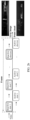
- FIG. 1 is a diagram of an application architecture according to an embodiment of this application.
- a 3D point cloud obtained through measurement by a lidar includes spatial location and intensity information of each point.
- the intensity information may be independently indicated as a 2D gray image. Because the 2D gray image and the 3D point cloud are collected in a same light field, information about the 2D gray image is completely included in the 3D point cloud. When a problem of a point cloud hole or a missing point cloud occurs in the 3D point cloud, the intensity information (the 2D gray image) included in the 3D point cloud also suffers the same problem.
- a solution is provided, that is, the lidar is disposed to obtain intensity information (a 2D gray image) of a same scenario under ambient light (without a laser).
- the another 2D gray image may be used as a reference for complementing lost information on the 3D point cloud.
- the lidar sequentially collects data by using a point (point) or a line as a unit.
- a time sequence of a laser light is preset.
- a collection cycle t1 and a collection cycle t2 are included.
- the laser light is turned off (Laser OFF), and a gray image (Gray image) is obtained.
- t2 the laser light is turned on (Laser ON), and a point cloud (Point cloud) is obtained.
- an image processing unit controls the laser light to be turned off, and there is only ambient light around.
- a lens (Lens) collects light in a field of view, and after the light passes through a filter (Filter), light is received by a photon detector.
- the photon detector converts an optical signal into an electrical signal and transmits the electrical signal to the image processing unit.
- the image processing unit obtains the gray image based on the electrical signal.
- the image processing unit controls the laser light to be turned on and emit a laser (Laser) in a field of view direction.
- the lens collects light in the field of view, and after the light passes through the filter (Filter), light is received by the photon detector.
- the photon detector converts an optical signal into an electrical signal and transmits the electrical signal to the image processing unit.
- the image processing unit obtains the point cloud based on the electrical signal.
- a 3D point cloud and a 2D gray image corresponding to the entire frame are obtained through synthesis, a contour and a feature of a target are extracted from the 2D gray image, and a 3D point cloud of a same unit is complemented, so as to obtain a final 3D point cloud.
- FIG. 2a is a diagram of a point cloud processing apparatus according to an embodiment of this application.
- the apparatus mainly includes a laser control unit, a photon detector, and a signal processing unit.
- the apparatus may further include: a radar scanning unit, a radar scanning control unit, a laser light compensation unit, an optical unit, and a frame data synthesis unit.
- the laser light compensation unit may correspond to the laser light in FIG. 1
- the optical unit may correspond to the lens in FIG. 1
- the photon detector may correspond to the photon detector in FIG. 1
- the signal processing unit and the frame data synthesis unit may be integrated into the image processing unit in FIG. 1
- the radar scanning control unit and the laser control unit may also be integrated into the image processing unit in FIG. 1 .
- the radar scanning control unit and the frame data synthesis unit are synchronized based on a frame signal, to control a rotation direction of the radar scanning unit, so as to change a field of view.
- the laser control unit and the photon detector implement ToF collection synchronization.
- the photon detector may always measure intensity information.
- intensity information measured during Laser ON includes laser information and ambient light information
- intensity information measured during Laser OFF includes only ambient light information.
- the photon detector may further measure depth information based on the laser. In this way, it can be ensured that at a start moment of Laser ON, the laser control unit controls the laser light compensation unit to be turned on, the photon detector starts to measure a laser distance to obtain the depth information, and simultaneously, the photon detector measures measurement the intensity information, to generate a 3D point cloud.
- Laser OFF the laser control unit controls the laser light compensation unit to be turned off, and the photon detector measures only the intensity information, to generate a 2D gray image.
- the signal processing unit and the frame data synthesis unit separately process signals collected during Laser ON and Laser OFF, to obtain data of an entire frame.
- Complete data of a frame includes the 3D point cloud and the corresponding 2D gray image.
- a lidar sequentially collects data by using a point or a line as a unit, the depth information and the intensity information are collected at each point or line in a time-division manner, and then these pieces of information are synthesized into the complete frame data.
- ON/OFF of the laser light compensation unit is strictly synchronized with a collection mode of the photon detector. During ON, the depth information is collected to obtain the 3D point cloud. During OFF, the intensity information is collected to obtain the 2D gray image.
- the photon detector used in the apparatus can implement a photon counting accumulation or histogram generation (Histogram Generation) function, and can respond to intensity characterization of a light field in a specific cycle.
- Histogram Generation histogram Generation
- FIG. 2b is a diagram of a time sequence chart.
- an inactive slot Inactive Slot 1, Inactive Slot 2, ..., or Inactive Slot n
- an active slot Active Slot 1, Active Slot 2, ..., or Active Slot n
- the 2D gray image Gray image
- the 3D point cloud Point cloud
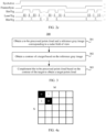
- FIG. 2c is a diagram of a control time sequence of time-division collection of a photon detector.
- the photon detector may keep ToF collection synchronization with the laser control unit, to achieve precise cooperation with the laser light compensation unit.
- time sequence control signals are set in this embodiment of this application, and the six time sequence control signals cooperate with each other, to implement the time sequence shown in FIG. 2c .
- a high electrical level indicates that a signal is active, and a low electrical level indicates that a signal is inactive.
- SysActive A system activation signal, where when the signal is at a high electrical level, another time sequence control signal is enabled.
- FrameSync An active frame signal, where when the signal is at a high electrical level, frame data is obtained; and when the signal is at a low electrical level, obtaining the frame data is stopped.
- SlotTrg A depth information collection mode of a unit, where when this signal is at a high electrical level, the photon detector enters the depth information collection mode, and in this case, the 3D point cloud is obtained.
- LaserTrg A laser pulse control signal, where when the signal is at a high electrical level, a laser beam is emitted.
- HistTrg Intensity information collection mode of a unit, where when this signal is at a high electrical level, the photon detector enters the intensity information collection mode, and in this case, the 2D gray image is obtained.
- a complete frame includes a plurality of groups of SlotTrg active cycles and HistTrg active cycles that alternate with each other. SlotTrg and HistTrg are enabled alternately, so that the depth information collection mode and the intensity information collection mode are implemented in a time-division manner.
- LaserTrg controls ON/OFF of the laser and controls ON/OFF of the laser to be strictly synchronized with the SlotTrg active cycles.
- a single SlotTrg active cycle includes a plurality of LaserTrg signals. In this way, a detection rate of the depth information of the target can be improved by using a multi-laser pulse.
- FIG. 3 is a flowchart of a process 300 of a lidar point cloud processing method according to an embodiment of this application.
- the process 300 may be performed by the image processing unit in the foregoing embodiment.
- the process 300 is described as a series of steps or operations. It should be understood that the process 300 may be performed in various orders and/or simultaneously, and is not limited to an execution order shown in FIG. 3 .
- the process 300 includes the following steps.
- Step 301 Obtain a to-be-processed point cloud and a reference gray image corresponding to a radar field of view.
- the to-be-processed point cloud is synthesized by point clouds of a plurality of units, and the reference gray image is synthesized by gray images of the plurality of units.
- the point cloud may include a plurality of units.
- the unit may be a single point in the point cloud, or the unit may be all points included in a line in the point cloud. For example, pixels corresponding to a complete point cloud of a frame are 576*96. If the unit is a single point, the point cloud includes 576*96 units. If the unit is a line, the point cloud may include 576 units or 96 units. It should be noted that another unit granularity may alternatively be used in embodiments of this application. This is not specifically limited.
- a sensor for example, a photon detector performs time-division collection, and may obtain a 3D point cloud and a 2D gray image of the unit.
- An active imaging (Active Imaging) signal is a point cloud formed based on photons collected by the sensor (for example, the photon detector) under a laser, and the point cloud includes depth information under laser illumination. Therefore, the active imaging signal may refer to the 3D point cloud of the unit, and the 3D point cloud includes spatial location and intensity information of the unit.
- the intensity information may be independently indicated as a 2D gray image. Because the 2D gray image and the 3D point cloud are collected in a same light field, information about the 2D gray image is completely included in the 3D point cloud. However, the 2D gray image also has the same hole or missing point as the 3D point cloud.
- An inactive imaging (Inactive Imaging) signal is an image formed based on photons collected by the sensor (for example, the photon detector) in ambient light, and the image includes intensity information under ambient light illumination. Therefore, the inactive imaging signal may refer to the 2D gray image of the unit.
- the image obtained through measurement by a lidar does not include the depth information but only includes the intensity information of the light because there is no laser.
- a point cloud of a first unit (the first unit is any one of the plurality of units) and a gray image of the first unit are separately collected by a same sensor in collection cycles that alternate with each other.
- the point clouds of the plurality of units may be synthesized into the to-be-processed point cloud, and the gray images of the plurality of units may be synthesized into the reference gray image.
- time-division collection of the single sensor for example, the photon detector
- Hardware costs are reduced, and device utilization can be improved.
- a same sensor alternately collects imaging signals (a point cloud and a gray image) of a same unit in short time, so that the point cloud and the gray image can correspond to a same field of view, to ensure coordinate consistency between the two. In this way, matching efficiency and accuracy between the two can be improved without a need to perform calibration and registration operations.
- the point clouds and the gray images may be obtained unit by unit in a predetermined order (for example, in a left-to-right order or a top-to-bottom order, or in a Z-shaped order, which is not specifically limited); the point clouds of the plurality of units are synthesized to obtain the to-be-processed point cloud; and the gray images of the plurality of units are synthesized to obtain the reference gray image.
- a predetermined order for example, in a left-to-right order or a top-to-bottom order, or in a Z-shaped order, which is not specifically limited
- the point clouds of the plurality of units are synthesized to obtain the to-be-processed point cloud
- the gray images of the plurality of units are synthesized to obtain the reference gray image.
- the point clouds of the units may be spliced based on locations of the units, to obtain the point cloud of an entire frame, and the gray images of the units are spliced, to obtain the gray image of the entire frame.
- the synthesized frame data includes the 3D point cloud (namely, the to-be-processed point cloud) synthesized by the point clouds of all the units and the 2D gray image (namely, the reference gray image) synthesized by the gray images of all the units.
- the gray image is obtained by using the sensor in a first collection cycle
- the point cloud is obtained by using the sensor in a second collection cycle.
- the first collection cycle and the second collection cycle alternate with each other, and a laser light is turned off in the first collection cycle, and the laser light is turned on in the second collection cycle.
- the first collection cycle may be a HistTrg active cycle
- the second collection cycle may be a SlotTrg active cycle.
- the two collection cycles alternate with each other, and a sequence of the two collection cycles is not limited.
- the photon detector When the laser is turned on, the photon detector collects the depth information; and when the laser is turned off, the photon detector collects the intensity information of a scene in ambient light, to obtain a point cloud and a gray image of a unit in a time-division manner.
- the gray image is obtained based on received signals obtained by the sensor through a plurality of times of collection in the first collection cycle.
- a dynamic range and a signal-to-noise ratio of the 2D gray image can be improved by accumulating intensity information of the plurality of times of collection.
- a single-photon detector is used as an example.
- FIG. 4a and FIG. 4b are diagrams of a photon counting principle of the single-photon detector. As shown in FIG. 4a , one unit may be indicated as an M*N array, and each small pixel (matrix element) in the array may be indicated as 0 or 1. Therefore, a dynamic range of the photon detector is 0-M*N.
- the dynamic range of the photon detector may be increased to 0-M*N*t, and precision and a signal-to-noise ratio of light intensity can be further improved.
- Step 302 Obtain a contour of a target based on the reference gray image.
- the target may be detected from the reference gray image based on a preset target of interest, and then target segmentation is performed on the reference gray image to obtain the contour of the target.
- enhancement processing may be first performed on the reference gray image, where the enhancement processing includes noising filtering and/or grayscale enhancement.
- FIG. 5 is a schematic flowchart of processing the reference gray image.
- enhancement processing is first performed on the gray image, and the processing includes conventional noising filtering and grayscale enhancement. This can help extract the target of interest (for example, a vehicle, a pedestrian, or a road plate).
- segmentation for the target of interest is performed on the enhanced gray image, to obtain the contour and an area of the target.
- Step 303 Complement the to-be-processed point cloud based on the contour of the target to obtain a target point cloud.
- a point cloud depth image may be obtained based on the to-be-processed point cloud; then, a target area corresponding to same coordinates is found from the point cloud depth image based on the coordinates of the contour of the target on the reference gray image; a to-be-complemented target area is obtained from the to-be-processed point cloud based on the target area; and a point complementing operation is performed on the to-be-complemented target area to obtain the target point cloud.
- FIG. 6 is a schematic flowchart of processing a point cloud.
- a target outer contour is segmented from the point cloud depth image based on guidance of the reference gray image. Because the point cloud and the gray image are for a same unit and are collected by a same sensor, coordinate systems of the point cloud and the gray image are completely the same, that is, coordinates of a pixel in the reference gray image and coordinates of corresponding pixel in the point cloud depth image are the same.
- a pixel extracted from a location that is on the point cloud depth image and that is indicated by the coordinates same as the coordinates of the contour of the target is also the contour of the target, and the outer contour of the target is segmented from the point cloud depth image.
- time-division collection of the single sensor can be implemented.
- a same sensor alternately collects imaging signals (a point cloud and a gray image) in short time, so that the point cloud and the gray image can correspond to a same field of view, so as to ensure coordinate consistency between the point cloud and the gray image.
- a gray image (2D gray image) may be used as a reference to complement a hole or a missing point in a point cloud (3D point cloud), to obtain a high-quality lidar point cloud.
- an interpolation area and an extrapolation area (the interpolation area is an internal missing point, and does not border the outer contour, and the extrapolation area is the opposite of the interpolation area) that are to be complemented are calculated based on a contour segmented in the 2D gray image and a depth hole image.
- a centrosymmetric circular interpolation kernel (the interpolation kernel may be obtained by using any technology, and this is not specifically limited in embodiments of this application) is generated based on a hole area, and a convolution and division operation is performed on the depth image and the depth hole image, to implement hole interpolation (in this step, point complementing of a hole point is implemented, but it cannot ensure that a shape obtained through complementing meets a real outer contour feature).
- Bilateral guidance is performed, based on the contour segmented in the 2D gray image, on the area in which the hole interpolation is implemented, and an extra point is removed, to implement accurate point cloud missing complementing.
- the 3D point cloud and the 2D gray image of a same field of view are obtained by using the single sensor in the lidar in a time-division manner, to ensure coordinate consistency between the 3D point cloud and the 2D gray image.
- the gray image may be used as a reference to complement a hole or a missing point in the point cloud, to obtain a high-quality lidar point cloud.
- hardware costs are reduced and device utilization is improved.
- An autonomous driving vehicle-mounted lidar is used as an example. Refer to the time sequence shown in FIG. 2c . Specific implementation steps are as follows:
- time for a single time of sampling performed by the photon detector is X1 ns.
- a gray image of a specific unit may be obtained by accumulating N times of sampling, that is, time for the N times of sampling is NX1 ns in total, to improve a signal-to-noise ratio and a dynamic range of the 2D gray image.
- time for a single time of sampling performed by the photon detector is X2 ns
- a point cloud of a specific unit may be obtained by accumulating M times of sampling, that is, time for the M times of sampling is MX2 ns in total. Echo signals of the laser are collected in the M times of sampling, to obtain depth information.
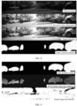
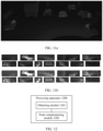
- FIG. 7 is a diagram of a 3D point cloud and a 2D gray image of a same field of view.
- FIG. 8 is a schematic flowchart of processing a 2D gray image.
- enhancement processing for example, noising filtering and/or grayscale enhancement
- target segmentation and contour extraction are facilitated.
- the target is detected from the enhanced gray image based on the preset target of interest. For example, a target of interest in a driving area is used as a to-be-complemented object (namely, the target).
- the target segmented from the enhanced gray image is matched with the target on the point cloud depth image through coordinate mapping, to obtain the target area that needs to be complemented on the point cloud depth image.
- FIG. 9 is a schematic flowchart of detecting a to-be-complemented area of a point cloud
- the contour of the target is mapped to the point cloud depth image (the point cloud depth image may be obtained by performing projection on the 3D point cloud) based on guidance of the contour of the target obtained through segmentation on the enhanced gray image, to obtain the target area on the point cloud depth image.
- a hole MASK no point or a point at infinity is filtered out
- convolution is performed on the hole MASK and the target area on the point cloud depth image, to obtain an actual to-be-complemented target area.
- the obtaining module 1201 is configured to: obtain a to-be-processed point cloud and a reference gray image corresponding to a radar field of view, where the to-be-processed point cloud is synthesized by point clouds of a plurality of units, the reference gray image is synthesized by gray images of the plurality of units, a point cloud of a first unit is obtained under laser illumination, a gray image of the first unit is obtained under ambient light illumination, the point cloud of the first unit and the gray image of the first unit are alternately collected by a same sensor, and the first unit is any one of the plurality of units; and obtain a contour of a target based on the reference gray image; and the point complementing module 1202 is configured to complement the to-be-processed point cloud based on the contour of the target to obtain a target point cloud.
- the obtaining module 1201 is specifically configured to: obtain, for the plurality of units, the point clouds and the gray images unit by unit in a predetermined order; synthesize the point clouds of the plurality of units to obtain the to-be-processed point cloud; and synthesize the gray images of the plurality of units to obtain the reference gray image.
- the obtaining module 1201 is specifically configured to: when the first unit is processed, obtain the gray image by using the sensor in a first collection cycle; and obtain the point cloud by using the sensor in a second collection cycle, where the first collection cycle and the second collection cycle alternate with each other, a laser light is turned off in the first collection cycle, and the laser light is turned on in the second collection cycle.
- the gray image is obtained based on received signals obtained by the sensor through a plurality of times of collection in the first collection cycle.
- the first unit includes one or more points obtained through a single time of collection.
- the obtaining module 1201 is specifically configured to: detect the target from the reference gray image based on a preset target of interest; and perform target segmentation on the reference gray image to obtain the contour of the target.
- the obtaining module 1201 is further configured to perform enhancement processing on the reference gray image, where the enhancement processing includes noising filtering and/or grayscale enhancement.
- the point complementing module 1202 is specifically configured to: obtain a point cloud depth image based on the to-be-processed point cloud; find, from the point cloud depth image based on coordinates of the contour of the target on the reference gray image, a target area corresponding to same coordinates; obtain a to-be-complemented target area on the to-be-processed point cloud based on the target area; and perform a point complementing operation on the to-be-complemented target area to obtain the target point cloud.
- the point complementing module 1202 is specifically configured to: obtain a hole image from the to-be-processed point cloud, where the hole image is used to describe a missing status of the to-be-processed point cloud; and perform convolution on the hole image and the target area to obtain the to-be-complemented target area.
- the apparatus in this embodiment may be configured to perform the technical solution of the method embodiment shown in FIG. 3 , an implementation principle and technical effect are similar, and details are not described herein again.
- the processor may be a general-purpose processor, a digital signal processor (digital signal processor, DSP), an application-specific integrated circuit (application-specific integrated circuit, ASIC), a field-programmable gate array (field-programmable gate array, FPGA) or another programmable logic device, a discrete gate or transistor logic device, or a discrete hardware component.
- DSP digital signal processor
- ASIC application-specific integrated circuit
- FPGA field-programmable gate array
- the general-purpose processor may be a microprocessor, or the processor may be any conventional processor or the like.
- a software module may be located in a mature storage medium in the art, such as a random access memory, a flash memory, a read-only memory, a programmable read-only memory, an electrically erasable programmable memory, or a register.
- the storage medium is located in the memory, and a processor reads information in the memory and completes the steps in the foregoing methods in combination with hardware of the processor.
- the memory in the foregoing embodiments may be a volatile memory or a nonvolatile memory, or may include both a volatile memory and a nonvolatile memory.
- the nonvolatile memory may be a read-only memory (read-only memory, ROM), a programmable read-only memory (programmable ROM, PROM), an erasable programmable read-only memory (erasable PROM, EPROM), an electrically erasable programmable read-only memory (electrically EPROM, EEPROM), or a flash memory.
- the volatile memory may be a random access memory (random access memory, RAM), used as an external cache.
- RAMs may be used, for example, a static random access memory (static RAM, SRAM), a dynamic random access memory (dynamic RAM, DRAM), a synchronous dynamic random access memory (synchronous DRAM, SDRAM), a double data rate synchronous dynamic random access memory (double data rate SDRAM, DDR SDRAM), an enhanced synchronous dynamic random access memory (enhanced SDRAM, ESDRAM), a synchlink dynamic random access memory (synchlink DRAM, SLDRAM), and a direct rambus dynamic random access memory (direct rambus RAM, DR RAM).
- static random access memory static random access memory
- DRAM dynamic random access memory
- DRAM dynamic random access memory
- SDRAM synchronous dynamic random access memory
- double data rate SDRAM double data rate SDRAM
- DDR SDRAM double data rate SDRAM
- ESDRAM enhanced synchronous dynamic random access memory
- synchlink dynamic random access memory synchlink dynamic random access memory
- direct rambus RAM direct rambus RAM
- the disclosed system, apparatus and method may be implemented in other manners.
- the described apparatus embodiment is merely an example.
- division into the units is merely logical function division and there may be another division manner in an actual implementation.
- a plurality of units or components may be combined or integrated into another system, or some features may be ignored or not performed.
- the displayed or discussed mutual couplings or direct couplings or communication connections may be implemented through some interfaces.
- the indirect couplings or communication connections between the apparatuses or units may be implemented in electrical, mechanical, or other forms.
- the units described as separate parts may or may not be physically separate, and parts displayed as units may or may not be physical units, that is, may be located at one location, or may be distributed on a plurality of network units. Some or all of the units may be selected based on actual requirements to achieve the objectives of the solutions of embodiments.
- the functions When the functions are implemented in the form of software functional unit and sold or used as an independent product, the functions may be stored in a computer-readable storage medium. Based on such an understanding, the technical solutions in this application essentially, or the part contributing to the conventional technology, or a part of the technical solutions may be implemented in a form of software product.
- the computer software product is stored in a storage medium and includes several instructions for instructing a computer device (a personal computer, a server, a network device, or the like) to perform all or a part of the steps of the methods in embodiments of this application.
- the foregoing storage medium includes any medium that can store program code, such as a USB flash drive, a removable hard disk drive, a read-only memory (read-only memory, ROM), a random access memory (random access memory, RAM), a magnetic disk, or an optical disc.
- program code such as a USB flash drive, a removable hard disk drive, a read-only memory (read-only memory, ROM), a random access memory (random access memory, RAM), a magnetic disk, or an optical disc.
Landscapes
- Engineering & Computer Science (AREA)
- Physics & Mathematics (AREA)
- General Physics & Mathematics (AREA)
- Remote Sensing (AREA)
- Radar, Positioning & Navigation (AREA)
- Theoretical Computer Science (AREA)
- Computer Networks & Wireless Communication (AREA)
- Computer Vision & Pattern Recognition (AREA)
- Electromagnetism (AREA)
- Multimedia (AREA)
- Health & Medical Sciences (AREA)
- Artificial Intelligence (AREA)
- Computing Systems (AREA)
- Databases & Information Systems (AREA)
- Evolutionary Computation (AREA)
- General Health & Medical Sciences (AREA)
- Medical Informatics (AREA)
- Software Systems (AREA)
- Quality & Reliability (AREA)
- Length Measuring Devices By Optical Means (AREA)
- Optical Radar Systems And Details Thereof (AREA)
Applications Claiming Priority (2)
| Application Number | Priority Date | Filing Date | Title |
|---|---|---|---|
| CN202211497989.2A CN118091696A (zh) | 2022-11-25 | 2022-11-25 | 激光雷达点云处理方法和装置 |
| PCT/CN2023/104076 WO2024109055A1 (zh) | 2022-11-25 | 2023-06-29 | 激光雷达点云处理方法和装置 |
Publications (2)
| Publication Number | Publication Date |
|---|---|
| EP4509878A1 true EP4509878A1 (de) | 2025-02-19 |
| EP4509878A4 EP4509878A4 (de) | 2025-09-03 |
Family
ID=91146478
Family Applications (1)
| Application Number | Title | Priority Date | Filing Date |
|---|---|---|---|
| EP23893155.4A Pending EP4509878A4 (de) | 2022-11-25 | 2023-06-29 | Verfahren und vorrichtung zur verarbeitung einer laserradarpunktwolke |
Country Status (4)
| Country | Link |
|---|---|
| US (1) | US20260016569A1 (de) |
| EP (1) | EP4509878A4 (de) |
| CN (1) | CN118091696A (de) |
| WO (1) | WO2024109055A1 (de) |
Families Citing this family (3)
| Publication number | Priority date | Publication date | Assignee | Title |
|---|---|---|---|---|
| CN121410706A (zh) * | 2024-07-19 | 2026-01-27 | 深圳引望智能技术有限公司 | 激光雷达成像方法及相关装置 |
| CN119027683B (zh) * | 2024-10-24 | 2025-01-03 | 深圳大学 | 基于空中点云先验引导的场景补全方法及系统 |
| CN121232201B (zh) * | 2025-12-04 | 2026-02-24 | 吉林大学 | 光学相控阵激光雷达及基于边缘轮廓的扫描方法 |
Family Cites Families (9)
| Publication number | Priority date | Publication date | Assignee | Title |
|---|---|---|---|---|
| US8976340B2 (en) * | 2011-04-15 | 2015-03-10 | Advanced Scientific Concepts, Inc. | Ladar sensor for landing, docking and approach |
| US10602242B2 (en) * | 2017-06-14 | 2020-03-24 | GM Global Technology Operations LLC | Apparatus, method and system for multi-mode fusion processing of data of multiple different formats sensed from heterogeneous devices |
| US10670725B2 (en) * | 2017-07-25 | 2020-06-02 | Waymo Llc | Determining yaw error from map data, lasers, and cameras |
| CN110147706B (zh) * | 2018-10-24 | 2022-04-12 | 腾讯科技(深圳)有限公司 | 障碍物的识别方法和装置、存储介质、电子装置 |
| CN110764070A (zh) * | 2019-10-29 | 2020-02-07 | 北科天绘(合肥)激光技术有限公司 | 基于三维数据与图像数据的数据实时融合处理方法、装置 |
| CN111340797B (zh) * | 2020-03-10 | 2023-04-28 | 山东大学 | 一种激光雷达与双目相机数据融合检测方法及系统 |
| CN111553859B (zh) * | 2020-04-29 | 2020-12-01 | 清华大学 | 一种激光雷达点云反射强度补全方法及系统 |
| CN113160327A (zh) * | 2021-04-09 | 2021-07-23 | 上海智蕙林医疗科技有限公司 | 一种点云补全的实现方法和系统 |
| CN114763997A (zh) * | 2022-04-14 | 2022-07-19 | 中国第一汽车股份有限公司 | 车辆采集到的雷达点云数据的处理方法、装置及电子设备 |
-
2022
- 2022-11-25 CN CN202211497989.2A patent/CN118091696A/zh active Pending
-
2023
- 2023-06-29 WO PCT/CN2023/104076 patent/WO2024109055A1/zh not_active Ceased
- 2023-06-29 EP EP23893155.4A patent/EP4509878A4/de active Pending
- 2023-06-29 US US18/994,063 patent/US20260016569A1/en active Pending
Also Published As
| Publication number | Publication date |
|---|---|
| WO2024109055A1 (zh) | 2024-05-30 |
| CN118091696A (zh) | 2024-05-28 |
| US20260016569A1 (en) | 2026-01-15 |
| EP4509878A4 (de) | 2025-09-03 |
Similar Documents
| Publication | Publication Date | Title |
|---|---|---|
| EP4509878A1 (de) | Verfahren und vorrichtung zur verarbeitung einer laserradarpunktwolke | |
| EP3438776B1 (de) | Verfahren, vorrichtung und computerprogramm für ein fahrzeug | |
| CN110084895B (zh) | 对点云数据进行标注的方法和设备 | |
| TWI709943B (zh) | 深度估計裝置、自動駕駛車輛及其深度估算方法 | |
| US10908257B2 (en) | Signal processing apparatus, signal processing method, and program | |
| JP6632474B2 (ja) | 監視装置、監視方法及び空港監視システム | |
| CN111971682A (zh) | 路面检测装置、利用了路面检测装置的图像显示装置、利用了路面检测装置的障碍物检测装置、路面检测方法、利用了路面检测方法的图像显示方法以及利用了路面检测方法的障碍物检测方法 | |
| US11999374B2 (en) | Spatial aware object detection by LIDAR and camera fusion based super-resolution | |
| US12306302B2 (en) | Image processing device, control program, and image processing method | |
| WO2022195954A1 (ja) | センシングシステム | |
| US20220373683A1 (en) | Image processing device, monitoring system, and image processing method | |
| CN115965847A (zh) | 交叉视角下多模态特征融合的三维目标检测方法和系统 | |
| US20230100249A1 (en) | Information processing device, control method, and non-transitory computer-readable media | |
| US12266080B2 (en) | Image processing device, image processing method, image processing program, and image processing system for generating high-resolution images with reflected light images and background light images | |
| CN111489397A (zh) | 一种成像设备标定方法以及装置 | |
| CN121069410A (zh) | 激光雷达与多光谱偏振成像融合的目标识别系统及方法 | |
| JP6379646B2 (ja) | 情報処理装置、測定方法及びプログラム | |
| CN112364741B (zh) | 无人机单目远距离障碍检测方法、装置及无人机 | |
| WO2022099225A1 (en) | Methods and systems for generating point clouds | |
| US20210258452A1 (en) | Image sensor circuitry for reducing effects of laser speckles | |
| WO2025195761A1 (en) | Method for object detection and optical detection system | |
| KR20250106037A (ko) | 차량 제어 장치 및 그 방법 | |
| WO2024204271A1 (ja) | 制御装置及び制御方法 | |
| WO2025204678A1 (ja) | 情報処理方法、情報処理装置、およびプログラム | |
| CN119904856A (zh) | 目标检测方法及装置 |
Legal Events
| Date | Code | Title | Description |
|---|---|---|---|
| STAA | Information on the status of an ep patent application or granted ep patent |
Free format text: STATUS: THE INTERNATIONAL PUBLICATION HAS BEEN MADE |
|
| PUAI | Public reference made under article 153(3) epc to a published international application that has entered the european phase |
Free format text: ORIGINAL CODE: 0009012 |
|
| STAA | Information on the status of an ep patent application or granted ep patent |
Free format text: STATUS: REQUEST FOR EXAMINATION WAS MADE |
|
| 17P | Request for examination filed |
Effective date: 20241202 |
|
| AK | Designated contracting states |
Kind code of ref document: A1 Designated state(s): AL AT BE BG CH CY CZ DE DK EE ES FI FR GB GR HR HU IE IS IT LI LT LU LV MC ME MK MT NL NO PL PT RO RS SE SI SK SM TR |
|
| A4 | Supplementary search report drawn up and despatched |
Effective date: 20250804 |
|
| RIC1 | Information provided on ipc code assigned before grant |
Ipc: G01S 17/89 20200101AFI20250729BHEP Ipc: G01S 13/89 20060101ALI20250729BHEP Ipc: G06V 10/80 20220101ALI20250729BHEP Ipc: G06T 7/11 20170101ALI20250729BHEP Ipc: G01S 7/48 20060101ALI20250729BHEP Ipc: G06T 7/12 20170101ALI20250729BHEP Ipc: G06T 7/13 20170101ALI20250729BHEP |
|
| DAV | Request for validation of the european patent (deleted) | ||
| DAX | Request for extension of the european patent (deleted) |