EP4510058A1 - Dispositif de détection et de manipulation de différents types de porteurs de charge sur une navette de transport - Google Patents
Dispositif de détection et de manipulation de différents types de porteurs de charge sur une navette de transport Download PDFInfo
- Publication number
- EP4510058A1 EP4510058A1 EP24194463.6A EP24194463A EP4510058A1 EP 4510058 A1 EP4510058 A1 EP 4510058A1 EP 24194463 A EP24194463 A EP 24194463A EP 4510058 A1 EP4510058 A1 EP 4510058A1
- Authority
- EP
- European Patent Office
- Prior art keywords
- shuttle
- underride
- load
- load carrier
- sensor arrangement
- Prior art date
- Legal status (The legal status is an assumption and is not a legal conclusion. Google has not performed a legal analysis and makes no representation as to the accuracy of the status listed.)
- Pending
Links
Images

Classifications
-
- G—PHYSICS
- G06—COMPUTING OR CALCULATING; COUNTING
- G06Q—INFORMATION AND COMMUNICATION TECHNOLOGY [ICT] SPECIALLY ADAPTED FOR ADMINISTRATIVE, COMMERCIAL, FINANCIAL, MANAGERIAL OR SUPERVISORY PURPOSES; SYSTEMS OR METHODS SPECIALLY ADAPTED FOR ADMINISTRATIVE, COMMERCIAL, FINANCIAL, MANAGERIAL OR SUPERVISORY PURPOSES, NOT OTHERWISE PROVIDED FOR
- G06Q10/00—Administration; Management
- G06Q10/08—Logistics, e.g. warehousing, loading or distribution; Inventory or stock management
-
- B—PERFORMING OPERATIONS; TRANSPORTING
- B66—HOISTING; LIFTING; HAULING
- B66F—HOISTING, LIFTING, HAULING OR PUSHING, NOT OTHERWISE PROVIDED FOR, e.g. DEVICES WHICH APPLY A LIFTING OR PUSHING FORCE DIRECTLY TO THE SURFACE OF A LOAD
- B66F9/00—Devices for lifting or lowering bulky or heavy goods for loading or unloading purposes
- B66F9/06—Devices for lifting or lowering bulky or heavy goods for loading or unloading purposes movable, with their loads, on wheels or the like, e.g. fork-lift trucks
- B66F9/075—Constructional features or details
- B66F9/0755—Position control; Position detectors
-
- B—PERFORMING OPERATIONS; TRANSPORTING
- B65—CONVEYING; PACKING; STORING; HANDLING THIN OR FILAMENTARY MATERIAL
- B65G—TRANSPORT OR STORAGE DEVICES, e.g. CONVEYORS FOR LOADING OR TIPPING, SHOP CONVEYOR SYSTEMS OR PNEUMATIC TUBE CONVEYORS
- B65G1/00—Storing articles, individually or in orderly arrangement, in warehouses or magazines
- B65G1/02—Storage devices
- B65G1/04—Storage devices mechanical
- B65G1/137—Storage devices mechanical with arrangements or automatic control means for selecting which articles are to be removed
- B65G1/1371—Storage devices mechanical with arrangements or automatic control means for selecting which articles are to be removed with data records
-
- B—PERFORMING OPERATIONS; TRANSPORTING
- B66—HOISTING; LIFTING; HAULING
- B66F—HOISTING, LIFTING, HAULING OR PUSHING, NOT OTHERWISE PROVIDED FOR, e.g. DEVICES WHICH APPLY A LIFTING OR PUSHING FORCE DIRECTLY TO THE SURFACE OF A LOAD
- B66F9/00—Devices for lifting or lowering bulky or heavy goods for loading or unloading purposes
- B66F9/06—Devices for lifting or lowering bulky or heavy goods for loading or unloading purposes movable, with their loads, on wheels or the like, e.g. fork-lift trucks
- B66F9/063—Automatically guided
-
- B—PERFORMING OPERATIONS; TRANSPORTING
- B66—HOISTING; LIFTING; HAULING
- B66F—HOISTING, LIFTING, HAULING OR PUSHING, NOT OTHERWISE PROVIDED FOR, e.g. DEVICES WHICH APPLY A LIFTING OR PUSHING FORCE DIRECTLY TO THE SURFACE OF A LOAD
- B66F9/00—Devices for lifting or lowering bulky or heavy goods for loading or unloading purposes
- B66F9/06—Devices for lifting or lowering bulky or heavy goods for loading or unloading purposes movable, with their loads, on wheels or the like, e.g. fork-lift trucks
- B66F9/065—Devices for lifting or lowering bulky or heavy goods for loading or unloading purposes movable, with their loads, on wheels or the like, e.g. fork-lift trucks non-masted
-
- B—PERFORMING OPERATIONS; TRANSPORTING
- B66—HOISTING; LIFTING; HAULING
- B66F—HOISTING, LIFTING, HAULING OR PUSHING, NOT OTHERWISE PROVIDED FOR, e.g. DEVICES WHICH APPLY A LIFTING OR PUSHING FORCE DIRECTLY TO THE SURFACE OF A LOAD
- B66F9/00—Devices for lifting or lowering bulky or heavy goods for loading or unloading purposes
- B66F9/06—Devices for lifting or lowering bulky or heavy goods for loading or unloading purposes movable, with their loads, on wheels or the like, e.g. fork-lift trucks
- B66F9/075—Constructional features or details
- B66F9/20—Means for actuating or controlling masts, platforms, or forks
- B66F9/24—Electrical devices or systems
Definitions
- the present invention relates to a device for detecting and handling different types of load carriers on an under-ride shuttle, an under-ride shuttle comprising such a device, a system formed from such an under-ride shuttle and a plurality of load carriers of different types, and a method for detecting and handling different types of load carriers on an under-ride shuttle by means of a device according to the invention.
- under-drive shuttles As part of the increasing automation of logistics facilities, so-called under-drive shuttles have recently become increasingly important. These can autonomously or semi-autonomously transport loads on their top, such as different types of pallets, tables or trays with goods carried on them.
- under-drive shuttles are equipped with a vehicle body with wheels on it and with a height-adjustable load-bearing platform or loading area.
- under-ride shuttles In order to pick up the above-mentioned type of loads and in particular load carriers, these are either driven under by a corresponding under-ride shuttle, either directly in the case of tables, or in a transfer station in the case of pallets or trays, and the loading area or load-bearing platform on the top of the under-ride shuttle is raised until the load is lifted off the ground or the transfer station, is carried on the under-ride shuttle and can then be transported to a designated location and handed over or deposited again.
- Generic underride shuttles are usually designed for omnidirectional movement and their operation is coordinated and controlled via a control system.
- the vehicle can be provided with elements for securing the load in a receiving position, such as locking elements or recesses that interact with the load and prevent the load from slipping during travel.
- elements for securing the load in a receiving position such as locking elements or recesses that interact with the load and prevent the load from slipping during travel.
- this is only possible if the load is correctly picked up, so detecting the correct picking position is also important for safe transport. Since the corresponding protective fields are spanned by sensors attached to the underride shuttle, it can only be guaranteed that the protective fields intended for the respective detected load carrier match the outer contour of the load if the load is correctly picked up and secured.
- the device according to the invention for detecting and handling different types of load carriers on an underride shuttle comprises a first sensor arrangement which is designed to detect the correct reception of a load carrier on a load-carrying platform of the underride shuttle and to output corresponding first sensor data, a second sensor arrangement which is of a different sensor type than the first sensor arrangement and is designed to provide information regarding the type of load carrier and to output corresponding second sensor data, and a control unit which is operatively coupled to the first sensor arrangement and the second sensor arrangement in order to receive the first and second sensor data, wherein the control unit is configured, when the load carrier is correctly picked up by the first sensor arrangement, to output control signals based on the detected type of load carrier, which control signals are intended to adapt at least one operating parameter of the underride shuttle.
- load carriers can refer, for example, to their geometry and in particular their external dimensions and/or their weight.
- load carriers with a non-square or otherwise non-rotationally symmetrical outline in plan view with respect to all possible receiving configurations, several possible orientations thereof with respect to the vehicle body of the underride shuttle can also be understood as different types of load carriers within the meaning of the present invention.
- suitable measures can also be initiated automatically, for example notifying an operator or even immediately shutting down the corresponding vehicle or, alternatively, parking or setting down the corresponding load carrier and, if necessary, carrying out another attempt to pick it up correctly.
- this can comprise at least one inductive sensor and/or at least one optical sensor, in particular at least one light barrier, and/or the first sensor arrangement can be position-sensitive in the millimeter range, i.e. that a positioning of the corresponding charge carrier can be determined with an accuracy of less than 1 cm.
- the inductive sensor mentioned can interact with a corresponding passive element on the charge carrier, for example a simple metallic section which, due to its inductance, can trigger a signal when present in the vicinity of the corresponding sensor in the range of the specified accuracy, while an optical sensor and in particular a light barrier detects the presence of a charge carrier or a section thereof in a predetermined spatial area in a known manner.
- a corresponding passive element on the charge carrier for example a simple metallic section which, due to its inductance, can trigger a signal when present in the vicinity of the corresponding sensor in the range of the specified accuracy
- an optical sensor and in particular a light barrier detects the presence of a charge carrier or a section thereof in a predetermined spatial area in a known manner.
- the first sensor arrangement can comprise at least two spaced-apart sensors, which can preferably be arranged opposite one another, in particular diagonally opposite one another, on the underride shuttle. Accordingly, the at least two sensors of the first sensor arrangement can be positioned, for example, in the area of opposite corners on the top of the underride shuttle. Alternatively, the sensor arrangement can detect the load carrier in two orthogonal spatial directions, for example by two optical measuring devices oriented perpendicular to each other.
- the second sensor arrangement can comprise, for example, a unit for reading a passive or active data carrier assigned to the load carrier, for example an NFC, RFID, Bluetooth LE or QR code reading unit.
- a passive or active data carrier assigned to the load carrier for example an NFC, RFID, Bluetooth LE or QR code reading unit.
- the above examples of passive and active data carriers that can be assigned to the load carriers each enable coding of larger amounts of data, which are suitable for distinguishing and identifying an almost arbitrarily large number of different types of load carriers.
- the second arrangement can be set up to be able to distinguish between at least 10, preferably at least 100 different types of load carriers, the specific number being dependent on the amount of data that can be encoded on the corresponding selected data carrier.
- the second sensor unit is preferably designed to read corresponding data carriers with a tolerance of more than 1 cm, in particular at least 10 cm. This ensures a certain minimum distance so that the associated load carrier does not have to rest on the sensor in order to avoid mechanical stress. On the other hand, a detection area that is too large could lead to incorrect identifications, for example if there are other data carriers in the load to be transported.
- the provision of the corresponding tolerance also means that the arrangement of a corresponding data carrier on the load carrier or the load is not position-sensitive or has a certain tolerance. Specifically, for example, NFC or Bluetooth LE units do not have to be placed on the load carrier with an accuracy of 1 cm in order to be able to be read reliably by the underdrive shuttle.
- the tolerance means that the optical unit for reading such a code can read it in a range of (1 cm x 1 cm + size of the code), in particular (10 cm x 10 cm + size of the code).
- the second sensor unit is further preferably designed to read different data carriers in different rotational positions of the load carrier or the load relative to the underride shuttle. Since the underride shuttle and/or the load carrier generally have rotational symmetry, the load or the load carrier can be picked up in different ways. In such a case, it can be provided that different data carriers are present on the load or the load carrier and at least a second sensor unit is arranged on the underride shuttle.
- the range of the data connection or the data transmission technology between the second sensor unit and the data carrier is selected such that, depending on the orientation of the load and the underride shuttle, only exactly one data carrier is read out and the relative orientation can be derived from this, for example, a load carrier of type A with dimensions of 300 mm x 400 mm corresponds to a load carrier with dimensions of 400 mm x 300 mm when rotated by 90°.
- geometric data and/or, for example, the permissible weight of the corresponding load carrier can be encoded directly on the passive or active data carriers mentioned, which in principle enables any number of load carriers to be distinguished, while on the other hand it would also be conceivable to provide an identifier for a specific type of load carrier or a type ID of the load carrier, which can be compared with type data stored in a data storage device assigned to the control unit in order to be able to derive the required information about the corresponding type of load carrier.
- the present invention relates to an underride shuttle comprising a vehicle body with a plurality of wheels, a load-bearing platform that can be displaced vertically relative to the vehicle body, a device for detecting and handling different types of load carriers on the underride shuttle of the type according to the invention just described, and a central control unit, wherein the central The control unit of the under-ride shuttle is operatively coupled or integrated with the control unit of the device.
- the functionality of the control unit of the device can thus also be provided directly by the central control unit of the under-ride shuttle or a solution with distributed hardware can be used, which can allow a higher degree of modularization, in which case the two control units mentioned above are in communicative connection with one another.
- the underride shuttle can comprise at least one scanner unit which is designed to monitor a protective field in the surroundings of the underride shuttle for the presence of objects, wherein the central control unit of the underride shuttle or a further control unit coupled to the central control unit, for example a dedicated security system, can be designed to adapt this protective field based on the detected type of load carrier. This is necessary for geometric reasons, since the load carriers picked up typically protrude beyond the floor plan of the underride shuttle.
- Such protective fields can also be adapted to different operating parameters of the vehicle, for example its speed or its current direction of travel.
- the at least one scanner unit mentioned serves to prevent collisions with moving and immovable objects and represents an essential safety device for such underride shuttles.
- LIDAR sensors can be used, for example, which are used in combination with monitoring the speed and steering of the underride shuttle. Accordingly, in the inventive design of an underride shuttle just described, a dedicated geometry of such protective fields can be initialized depending on the respective geometry of the load carrier currently being carried, and the correct and correlated fields can be activated and monitored during operation of the underride shuttle.
- the corresponding at least one operating parameter to be adapted can comprise a maximum speed, a maximum acceleration, a minimum curve radius and/or a maximum lateral acceleration of the underride shuttle, by means of which a safe transport of the load is ensured for the different types of load carriers in each operating situation of the vehicle.
- At least one further sensor unit on the underride shuttle according to the invention for determining a further state parameter of the load carrier, the underride shuttle or its surroundings, for example a weight sensor unit which is designed to determine a weight of a picked-up load carrier, wherein the central control unit can also be designed to at least one operating parameter of the underride shuttle to additionally take into account the at least one further state parameter.
- the said operating parameters such as maximum speed or maximum acceleration, can be adapted based on both the type of load carrier and the additionally recorded further state parameter.
- the present invention further relates to a system formed from an underride shuttle of the type just described and a plurality of load carriers of different types, each of which is designed to be accommodated and transportable on the load-carrying platform of the underride shuttle, each of the load carriers being assigned at least one passive or active data carrier on which information relating to the type of load carrier is encoded.
- this can either be directly stored data on the type of load carrier, for example geometric dimensions and/or a weight thereof, or a type ID or a unique identifier of the load carrier can be encoded, from which the control unit of the device according to the invention provided in the underride shuttle can derive the corresponding information by means of a database comparison.
- the corresponding data carrier of each of the load carriers encodes a unique identifier, for example an alphanumeric code which is only assigned once and thus enables a 1:1 assignment to the respective load carrier.
- the present invention relates to a method for detecting and handling different types of load carriers on an underride shuttle by means of a device according to the invention of the type described above, optionally in an underride shuttle according to the invention, comprising detecting a correct pick-up of a load carrier on a load-carrying platform of the underride shuttle by means of the first sensor arrangement, detecting information regarding the type of load carrier by means of the second sensor arrangement, and in the case of a correct pickup of the load carrier detected by the first sensor arrangement, adjusting at least one operating parameter of the underride shuttle based on the type of load carrier.
- the at least one operating parameter of the underride shuttle can include a protective field in the environment of the underride shuttle, a maximum speed, a maximum acceleration, a minimum curve radius and/or a maximum lateral acceleration of the underride shuttle.
- the recording of information regarding the type of load carrier can be carried out in a redundant manner, either by means of redundant hardware, i.e. in particular by using a plurality of reading units associated with the second sensor arrangement and/or by redundant, i.e. multiple coding of the corresponding information on the at least one data carrier associated with the load carrier.
- redundant hardware i.e. in particular by using a plurality of reading units associated with the second sensor arrangement and/or by redundant, i.e. multiple coding of the corresponding information on the at least one data carrier associated with the load carrier.
- the recording of information regarding the type of load carrier can also include validating the recorded information.
- This can prevent unauthorized modification or duplication of one of the load carriers used here, which in the present application helps to protect security-relevant parameters against such manipulation.
- a verification can be carried out during the production of the load carriers that the data encoded on the corresponding data carrier matches the type of load carrier, whereupon a so-called "validation flag" can then be written to the data carrier.
- the control unit of the corresponding vehicle only accepts data carriers that have this validation flag.
- hash values are calculated on the basis of a private key using logic that is only known in production and control. These hash values are based on the unique identifier of the corresponding load carrier and can be evaluated to validate the corresponding load carrier.
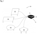
- a system 100 according to the invention is shown schematically, which consists of an underride shuttle 10 according to the invention and a plurality of load carriers 102 - 108 of different types.
- the load carriers 102 - 108 have different shapes and external dimensions when viewed from above, but are all designed as load tables that can be driven under and lifted directly by the underdrive shuttle 10 and have different rotational symmetries.
- other types of load carriers could also be conceivable as part of the system 100, for example pallets or trays, which would then possibly have to be driven under in a suitable transfer station, since they themselves do not have sufficient construction height with respect to a subsurface.
- the underride shuttle 10 in turn comprises a vehicle body 12, in which, among other things, some of the components described below are accommodated, as well as, for example, a drive system, an energy storage device, a control unit with corresponding peripheral devices and a lifting device for the load-bearing platform 14, which is height-adjustable with respect to the vehicle body 12 and thus the ground and is designed to accommodate the load carriers 102 - 108.
- a corresponding underride shuttle can carry an interface unit which is designed to accommodate certain load carriers and comprises the first and second sensor units.
- the underride shuttle and the corresponding interface unit are to be regarded as a structural unit.
- FIG. 2 A top view of the underride shuttle 10 and thus in particular of the top side of the load-bearing platform 14 is also shown in Figure 2
- two support sections 16a and 16b are provided symmetrically on the top of the load-bearing platform 14, of which the Figure 2 the lower one is provided with an anti-slip pad, while for reasons of clarity this pad has not been shown on the upper one.
- projections, depressions or similar can also be provided on the upper side of the load-bearing platform, which interact with corresponding counter-elements of the load carriers 102 - 108 to facilitate correct positioning and alignment in a recorded state.
- the load carriers 102 - 108 are provided with counter elements at suitable locations on their undersides, for example metal sections and/or recesses and/or non-metallic sections, which allow detection thereof over a short range, thereby enabling the desired precision of detection in the millimeter range.
- optical sensors could also be used as corresponding sensor units, for example, in particular light barriers, by means of which such precise detection of the correct reception of the load carriers 102 - 108 is also possible.
- a different number of sensors could also be installed for this purpose as part of the first sensor arrangement 18.
- an RFID reading unit 20a is provided on the top of the load-carrying platform 14, which forms part of a second sensor arrangement 20 and is designed to read an RFID tag attached to a suitable position on the load carriers 102 - 108 in order to record information regarding the type of load carrier that is encoded on the RFID tag.
- the second sensor arrangement 20 could also be used for the second sensor arrangement 20, for example an NFC, Bluetooth LE or QR code reading unit, if the load carriers 102 - 108 are equipped with such active or passive data carriers.
- configurations are also conceivable in which in which the second sensor arrangement 20 comprises more than one reading unit 20a, for example for reasons of redundancy or plausibility.
- the data volumes that can be encoded by the data carriers mentioned are sufficient to be able to clearly identify an almost unlimited number of different types of load carriers for practical use, and their respective ranges are also suitable for the operation just outlined.
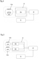
- FIG. 3 The components of a device according to the invention for detecting and handling the different types of load carriers 102 - 108 of the underride shuttle 10 are to be explained on the basis of the schematic diagram shown therein.
- Figures 1 and 2 The device itself is in Figure 3 designated as a whole by the reference numeral 22, wherein the Figure 3 further shows further components of the underride shuttle 10, which are not to be understood as components of the device 22.
- the device 22 comprises the first sensor arrangement 18 with its two fields of inductive sensors 18a and 18b on the top of the underride shuttle 10 for outputting sensor data which indicate correct reception of one of the load carriers 102 - 108 on the load-handling platform 14.
- the device 22 comprises the second sensor arrangement 20 with its RFID reading unit 20a, which outputs information regarding the type of load carrier 102 - 108.
- the respective sensor data are output to a control unit 24, which processes them in a suitable manner, for example by assigning identification data provided by the second sensor arrangement 20 to a specific type of load carrier 102 - 108 via a lookup table stored in an associated memory 24a and, on this basis, outputting control signals which are intended to adapt at least one operating parameter of the underride shuttle 10.
- the control unit 24 receives the required data for the detected data carrier by means of a wireless communication connection (not shown), such as WLAN, for example. at a central unit of the logistics facility in which the underdrive shuttle 10 is operated.
- control unit 24 as in Figure 3 shown, be communicatively coupled to a central control unit 26 of the underride shuttle 10, while in an alternative variant the functionality of the control unit 24 could also be taken over directly by the central control unit 26, so that only a single hardware would have to be used here, such as a suitable microprocessor or controller.
- the central control unit 26 can now adapt the operation of various components of the underride shuttle 10 on the basis of the control signals from the control unit 24 of the device 22, for example a drive system 28 shown here only schematically with regard to a maximum permissible speed, acceleration or lateral acceleration or a maximum permissible curve radius.
- a protective field of at least one scanner unit 30 can be adapted on the basis of the detected type of load carrier 102 - 108, in which case the outline of such a load carrier 102 - 108 would have to be taken into account in particular. It should be noted that in a further variant not shown here, an additional separate control unit can also be provided for adapting the protective fields, which can form part of a dedicated safety system of the underride shuttle 10 and would also be in communicative connection with the central control unit 26.
- suitable measures can also be taken, for example notification of a human operator via suitable communication and/or display means and/or a temporary shutdown of the underride shuttle 10 as a whole.
- At least one further sensor unit 32 can be included in the underride shuttle 10, for example a weight sensor unit which detects a weight of a picked-up load carrier 102 - 108.
- the data determined in this way can also be taken into account by the central control unit 26 when adapting the at least one operating parameter.
- a total of three data sections are provided on the RFID tag 102a assigned to the corresponding load carrier 102, two of which independently and redundantly encode a type identifier (Load Type ID) of the corresponding type of load carrier 102, while the remaining third data section encodes a unique hardware identifier (HW ID) of the specific load carrier 102.
- the second sensor unit 20 processes the first type identifier together with the hardware identifier and then, in a second step, the other type identifier, also together with the hardware identifier.
- the control unit 24 compares whether the two type identifiers match and whether the same load carrier 102 was read by additionally comparing the hardware identifiers read out in the two steps.
- Parallel to this data stream from the second Sensor arrangement 20 processes a further data stream from the control unit 24, which originates from the first sensor arrangement 18 and concerns a correct reception of the load carrier 102 on the underride shuttle 10.
- two RFID tags 102b on the load carrier 102 are read independently of one another by separate and sufficiently spaced RFID readers 20a, 20b, which each encode only one type identifier in order to achieve redundancy and plausibility that meets the highest security standards.
- the two RFID tags 102b in the Figures 4 and 5 can be used, for example, to adapt protective fields in the underride shuttle 10 depending on the type of load carrier to be picked up, without this impairing the operational safety of the underride shuttle 10.
- Reading the load type ID twice serves to increase safety or to achieve a specified safety standard. Since reading the load type ID or recognizing the load carrier is a safety-relevant function that has a direct impact on the operational safety of the underride shuttle 10, redundant recognition of the load carrier type is necessary.
- a further data section can be provided on the RFID tags 102a, 102b, which serves as a validation flag, whereby the control unit 24 in this context will only accept load carriers 102 - 108 on whose RFID tags 102a, 102b a valid validation flag is encoded.
- These can already be generated in the production of the respective load carrier 102 - 108 using suitable cryptographic methods and then validated by the control unit 24 during the reading of the corresponding RFID tag 102a, 102b, for example using a hashing method known per se.
Landscapes
- Engineering & Computer Science (AREA)
- Transportation (AREA)
- Structural Engineering (AREA)
- Mechanical Engineering (AREA)
- Civil Engineering (AREA)
- Life Sciences & Earth Sciences (AREA)
- Geology (AREA)
- Business, Economics & Management (AREA)
- Economics (AREA)
- Entrepreneurship & Innovation (AREA)
- Quality & Reliability (AREA)
- Combustion & Propulsion (AREA)
- Chemical & Material Sciences (AREA)
- Human Resources & Organizations (AREA)
- Marketing (AREA)
- Operations Research (AREA)
- Development Economics (AREA)
- Strategic Management (AREA)
- Tourism & Hospitality (AREA)
- Physics & Mathematics (AREA)
- General Business, Economics & Management (AREA)
- General Physics & Mathematics (AREA)
- Theoretical Computer Science (AREA)
- Control Of Position, Course, Altitude, Or Attitude Of Moving Bodies (AREA)
- Automatic Assembly (AREA)
Applications Claiming Priority (1)
| Application Number | Priority Date | Filing Date | Title |
|---|---|---|---|
| DE102023122082.9A DE102023122082A1 (de) | 2023-08-17 | 2023-08-17 | Vorrichtung zur Erfassung und Handhabung unterschiedlicher Typen von Ladungsträgern an einem Unterfahr-Shuttle |
Publications (1)
| Publication Number | Publication Date |
|---|---|
| EP4510058A1 true EP4510058A1 (fr) | 2025-02-19 |
Family
ID=92424311
Family Applications (1)
| Application Number | Title | Priority Date | Filing Date |
|---|---|---|---|
| EP24194463.6A Pending EP4510058A1 (fr) | 2023-08-17 | 2024-08-14 | Dispositif de détection et de manipulation de différents types de porteurs de charge sur une navette de transport |
Country Status (3)
| Country | Link |
|---|---|
| US (1) | US20250059012A1 (fr) |
| EP (1) | EP4510058A1 (fr) |
| DE (1) | DE102023122082A1 (fr) |
Citations (3)
| Publication number | Priority date | Publication date | Assignee | Title |
|---|---|---|---|---|
| WO2016130338A1 (fr) * | 2015-02-13 | 2016-08-18 | Amazon Technologies Inc. | Récipients de stockage intelligents multi-fonctions modulaires |
| CN216512679U (zh) * | 2021-10-26 | 2022-05-13 | 深圳市祺丰智能机器人科技有限公司 | 一种agv平板举升机器人 |
| KR20220067668A (ko) * | 2020-11-18 | 2022-05-25 | 부산항만공사 | 스마트 물류 이송 셔틀 |
Family Cites Families (4)
| Publication number | Priority date | Publication date | Assignee | Title |
|---|---|---|---|---|
| DE202014102274U1 (de) * | 2014-05-14 | 2014-06-16 | SSI Schäfer AG | Folienerkennung und Palettentyperkennung mittels Kanalfahrzeug in einem Kanalregallager |
| CN111665829B (zh) * | 2019-03-06 | 2024-10-29 | 物流及供应链多元技术研发中心有限公司 | 具有负载稳定性判断的自动导引车辆 |
| DE102019213444A1 (de) * | 2019-09-04 | 2021-03-04 | Zf Friedrichshafen Ag | System zur Zustandsüberwachung von Vorrichtungen |
| DE102019215176A1 (de) * | 2019-10-02 | 2021-04-08 | Robert Bosch Gmbh | Flurförderzeug, eingerichtet für den fahrerlosen, autonom agierenden Betrieb für eine zu transportierende Last |
-
2023
- 2023-08-17 DE DE102023122082.9A patent/DE102023122082A1/de active Pending
-
2024
- 2024-08-13 US US18/802,395 patent/US20250059012A1/en active Pending
- 2024-08-14 EP EP24194463.6A patent/EP4510058A1/fr active Pending
Patent Citations (3)
| Publication number | Priority date | Publication date | Assignee | Title |
|---|---|---|---|---|
| WO2016130338A1 (fr) * | 2015-02-13 | 2016-08-18 | Amazon Technologies Inc. | Récipients de stockage intelligents multi-fonctions modulaires |
| KR20220067668A (ko) * | 2020-11-18 | 2022-05-25 | 부산항만공사 | 스마트 물류 이송 셔틀 |
| CN216512679U (zh) * | 2021-10-26 | 2022-05-13 | 深圳市祺丰智能机器人科技有限公司 | 一种agv平板举升机器人 |
Also Published As
| Publication number | Publication date |
|---|---|
| US20250059012A1 (en) | 2025-02-20 |
| DE102023122082A1 (de) | 2025-02-20 |
Similar Documents
| Publication | Publication Date | Title |
|---|---|---|
| EP2468678B1 (fr) | Chariot de manutention équipé d'un capteur pour détecter l'environnement spatial et procédé de fonctionnement d'un tel chariot de manutention | |
| EP3241801B1 (fr) | Procédé de surveillance de collision dans un chariot de manutention | |
| EP1898290B1 (fr) | Système de guidage pour chariots de manutention | |
| EP3446184B1 (fr) | Dispositif de sécurité et procédé de sécurité | |
| EP1728758B1 (fr) | Chariot de manutention avec une unité de commande électrique | |
| EP3634901B1 (fr) | Dispositif de levage de portique pour conteneurs guidé automatiquement et procédé de fonctionnement d'un tel dispositif de levage de portique | |
| DE19613386A1 (de) | Flurförderzeug, das wahlweise manuell oder automatisch betreibbar ausgebildet ist | |
| EP2385014B1 (fr) | Chariot de manutention doté d'un dispositif destiné à l'identification d'un produit de transport chargé et procédé destiné à l'identification d'un produit de transport chargé d'un chariot de manutention | |
| EP1307396B1 (fr) | Procede de chargement et dechargement automatiques d'unites de transport, en particulier d'unites de transport de marchandises | |
| DE102016220810A1 (de) | Proaktives Verringern von Schwingungen in einem Flurförderzeug | |
| DE102008027701A1 (de) | Steuerungsverfahren für Flurförderzeug | |
| EP4043386B1 (fr) | Système de guidage d'un chariot de manutention | |
| EP4510058A1 (fr) | Dispositif de détection et de manipulation de différents types de porteurs de charge sur une navette de transport | |
| EP3825731B1 (fr) | Capteur optoélectronique de sécurité et procédé de détermination sécurisée de position propre | |
| EP4286316A1 (fr) | Dispositif de détection d'un porte-charge porté sur une navette de sous-marin | |
| EP3976447A1 (fr) | Système comprenant un chariot tracteur et au moins un poste de transfert stationnaire | |
| DE102019118710A1 (de) | Verfahren und Verladesystem für eine Verladung von Ladungsträgern eines Warenlagers | |
| EP4065453B1 (fr) | Dispositif de transport, installation de traitement, procédé de transport et/ou de traitement d'objets | |
| EP4309012A1 (fr) | Station d'accueil pour porte-pièces dans un système de transport sans conducteur | |
| EP3984858B1 (fr) | Procédé de détermination des informations sur la propagation d'un support de marchandises dans un chariot de manutention à fonctionnement au moins partiellement automatisé | |
| DE102025104555B3 (de) | Verfahren zum be- und/oder entladen eines laderaums, insbesondere des laderaums eines lastkraftwagens, mit einem autonomen ladefahrzeug und absicherungssystem | |
| DE102024129074A1 (de) | Verfahren zum Betreiben einer technischen Anlage und technische Anlage | |
| DE102022112079A1 (de) | Schnittstelleneinheit zur Aufnahme einer Palette auf einem Unterfahr-Shuttle | |
| WO2026062183A1 (fr) | Système de transport d'objets dans une installation | |
| DE102022120397A1 (de) | Fahrerloses Transportsystem |
Legal Events
| Date | Code | Title | Description |
|---|---|---|---|
| PUAI | Public reference made under article 153(3) epc to a published international application that has entered the european phase |
Free format text: ORIGINAL CODE: 0009012 |
|
| STAA | Information on the status of an ep patent application or granted ep patent |
Free format text: STATUS: THE APPLICATION HAS BEEN PUBLISHED |
|
| AK | Designated contracting states |
Kind code of ref document: A1 Designated state(s): AL AT BE BG CH CY CZ DE DK EE ES FI FR GB GR HR HU IE IS IT LI LT LU LV MC ME MK MT NL NO PL PT RO RS SE SI SK SM TR |
|
| STAA | Information on the status of an ep patent application or granted ep patent |
Free format text: STATUS: REQUEST FOR EXAMINATION WAS MADE |
|
| 17P | Request for examination filed |
Effective date: 20250326 |