EP4510095A1 - Vorrichtung zum sammeln von pfandobjekten - Google Patents
Vorrichtung zum sammeln von pfandobjekten Download PDFInfo
- Publication number
- EP4510095A1 EP4510095A1 EP24194448.7A EP24194448A EP4510095A1 EP 4510095 A1 EP4510095 A1 EP 4510095A1 EP 24194448 A EP24194448 A EP 24194448A EP 4510095 A1 EP4510095 A1 EP 4510095A1
- Authority
- EP
- European Patent Office
- Prior art keywords
- elements
- recorded
- optical recognition
- consigned
- passage
- Prior art date
- Legal status (The legal status is an assumption and is not a legal conclusion. Google has not performed a legal analysis and makes no representation as to the accuracy of the status listed.)
- Pending
Links
Images



Classifications
-
- G—PHYSICS
- G07—CHECKING-DEVICES
- G07F—COIN-FREED OR LIKE APPARATUS
- G07F7/00—Mechanisms actuated by objects other than coins to free or to actuate vending, hiring, coin or paper currency dispensing or refunding apparatus
- G07F7/06—Mechanisms actuated by objects other than coins to free or to actuate vending, hiring, coin or paper currency dispensing or refunding apparatus by returnable containers, i.e. reverse vending systems in which a user is rewarded for returning a container that serves as a token of value, e.g. bottles
-
- G—PHYSICS
- G07—CHECKING-DEVICES
- G07F—COIN-FREED OR LIKE APPARATUS
- G07F7/00—Mechanisms actuated by objects other than coins to free or to actuate vending, hiring, coin or paper currency dispensing or refunding apparatus
- G07F7/005—Details or accessories
-
- G—PHYSICS
- G07—CHECKING-DEVICES
- G07F—COIN-FREED OR LIKE APPARATUS
- G07F7/00—Mechanisms actuated by objects other than coins to free or to actuate vending, hiring, coin or paper currency dispensing or refunding apparatus
- G07F7/06—Mechanisms actuated by objects other than coins to free or to actuate vending, hiring, coin or paper currency dispensing or refunding apparatus by returnable containers, i.e. reverse vending systems in which a user is rewarded for returning a container that serves as a token of value, e.g. bottles
- G07F7/0609—Mechanisms actuated by objects other than coins to free or to actuate vending, hiring, coin or paper currency dispensing or refunding apparatus by returnable containers, i.e. reverse vending systems in which a user is rewarded for returning a container that serves as a token of value, e.g. bottles by fluid containers, e.g. bottles, cups, gas containers
-
- G—PHYSICS
- G07—CHECKING-DEVICES
- G07F—COIN-FREED OR LIKE APPARATUS
- G07F9/00—Details other than those peculiar to special kinds or types of apparatus
- G07F9/009—User recognition or proximity detection
Definitions
- the present invention relates to a device for recognizing and collecting consigned objects.
- the present invention further relates to a method for managing such consigned objects.
- Returnable tableware items are becoming more and more frequent and numerous, in order to limit waste and protect the environment. They are also increasingly varied. Returnable items include different types of plates, dishes, glasses, cutlery, bottles, which complicates the management of their flows.
- Another object of the invention is to provide a method for managing a variety of consigned elements. Such a method aims in this case to facilitate the management of the flows of such elements, to facilitate the management of their stocks and/or to minimize the associated costs.
- the device 1 comprises a surface 2 for placing recorded elements D1, D2, D3...Dn, on which a user can place one or more recorded elements.
- the collection device 1 further comprises at least one optical recognition device 10 for recognizing the recorded element(s) D1, D2, D3...Dn, placed on the placing surface 2.
- Such an optical recognition device 10 comprises at least one optical sensor 100 for capturing the image of a recorded element D1, D2, D3...Dn, presented in its detection field 110.
- An optical sensor 100 designates any device capable of optically identifying an object such as a CMOS sensor or any equivalent. It can be combined with elements optical such as converging and/or diverging lenses.
- Several optical sensors 100 can be used in combination, for example at different locations, so as to capture the image of the recorded element from different angles. The optical captures of different optical sensors 100 can be combined to reconstruct a more precise image of the recorded element or a three-dimensional image.
- a consigned element D1, D2, D3...Dn can thus be recognized according to its two-dimensional profile, or its three-dimensional shape.
- a marking can be affixed to the consigned elements D1, D2, D3...Dn, so as to be able to be identified by one or more optical sensors 100.
- Such a marking can for example specify the nature of the consigned element, among a bottle, a glass, a plate, cutlery or consigned elements of any other nature.
- a marking makes it possible to determine the origin of a consigned element D1, D2, D3...Dn, in particular the supplier or the distributor.
- the marking can consist of a visible design on an external surface of a consigned element.
- the three-dimensional shape or a portion of the three-dimensional shape serves as a signature of a recorded element D1, D2, D3...Dn.
- fluorescent or phosphorescent labels may be used.
- the recognition of a recorded element D1, D2, D3...Dn can be done in the visible range.
- optical detection in a range such as ultraviolet or infrared is also possible.
- Mixed detection allowing optical captures to be combined in several optical ranges among infrared, visible and ultraviolet is conceivable.
- an optical marking can be identified exclusively in the ultraviolet or infrared range while the recorded element D1, D2, D3...Dn, is itself detected in the visible range.
- An optical sensor 100 may include a laser detection device.
- the optical recognition device 10 may further comprise a lighting system 101 oriented towards the recorded element(s) D1, D2, D3...Dn, so as to obtain a sufficiently precise image thereof.
- the lighting may for example comprise one or more rays of white light, in particular by means of LEDs or any equivalent. Lighting in the ultraviolet and/or infrared ranges is also possible.
- the lighting source may be close to the optical sensor(s ) 100 and oriented towards the placement surface 2. It is however possible to dissociate the lighting source from the optical sensor 100 for more uniform lighting. In this case, the lighting source(s) are arranged at a distance from the optical sensor(s), for example, opposite, or above the placement surface.
- the optical recognition device 10 may comprise a protection device 102 arranged around the optical sensor(s ) 100. Such a protection device aims in particular to avoid stray light.
- the surface and/or the color of the protection device 101 may be adapted to direct or diffuse the light from the lighting system 101 towards the recorded element(s ) D1, D2, D3...Dn.
- the optical recognition device 10 may be protected by a window from possible dirt coming from the recorded elements D1, D2, D3...Dn.
- mirrors acting as an angle return may be envisaged making it possible to orient the optical recognition device 10 differently, for example to limit its bulk.
- the optical recognition device 10 is arranged in proximity to the laying surface 2. It can for example be arranged laterally and oriented towards the laying surface 2. It can comprise several optical sensors 100 arranged on either side of the laying surface 2, facing each other or at an angle so as to combine several lateral views. Alternatively or in addition, the optical recognition device 10 can be arranged above the laying surface 2. Alternatively, the laying surface 2 may be transparent and allow an optical sensor to take captures from below the laying surface 2.
- the optical sensor(s ) 100 of the optical recognition device 10 can be adjusted in height, vertical inclination, and/or lateral orientation. They can for example be arranged laterally and oriented at a right angle to the laying surface 2 so as to capture the recorded elements at 90°, or oriented at a different angle between 30° and 90°, such as 40° or 50°. Alternatively or in addition, they can be placed higher and inclined downwards for a better three-dimensional view of the recorded elements arranged on the laying surface.
- the optical sensor(s ) 100 may be fixed. Alternatively, the optical sensor(s ) 100, or a portion thereof, may be orientable, manually or automatically. In the case of conveying the recorded elements, one or more of the optical sensors 100 may be adapted to automatically track the conveyed elements over a portion of their path.
- the optical recognition device 10 comprises the memory and the electronic devices suitable for recording the optical captures of the recorded elements D1, D2, D3...Dn, as well as any markings they contain. It further comprises at least one image processing module (not shown) for analyzing the optical captures and recognizing the recorded elements D1, D2, D3...Dn. Such image processing comprises, for example, measurements of sizes, angles and shapes of the recorded elements D1, D2, D3...Dn. Alternatively or in addition, it can determine the light reflection, light diffusion, or color of the recorded elements.
- the laying surface 2 may include at least one location 20 materialized by any suitable means and allowing the arrangement there correctly the recorded element(s ) D1, D2, D3...Dn, so as to be able to identify them easily.
- the location 20 can be materialized by a luminous indication such as a pointer or any optical projection on the placing surface 2. For example, a message such as "deposit here" can be projected for the user's attention.
- the placing surface 2 can itself be colored or printed with an indicative message.
- a hollow relief can be printed in the placing surface 2 so as to arrange the recorded elements there.
- several locations 20 can be materialized on the placing surface 2.
- the location 20 is arranged so as to present the recorded element(s) in front of the optical recognition device 10 in an optimal manner. In this case, the location 20 ensures that the recorded element(s) appear entirely in the detection field 110 of the optical recognition device 10.
- the placing surface 20 may comprise one or more supports specifically designed for a type of consigned element.
- a support may be presented to arrange cutlery there vertically rather than directly on the placing surface 2.
- the placing surface 2 is fixed, such that the recorded elements are directly deposited in the detection field 110 of the optical recognition device 10. Under these conditions, a scanning or switching device (not shown) can be activated after recognition of the recorded element to move it from the placing surface 2 to a storage bin. This arrangement is not preferred, however.
- the placing surface 2 is mobile. In particular, it makes it possible to place a consigned element in one location and transfer it into the detection field 110 of the device. optical recognition 10.
- the placing surface 2 may for this purpose be one or more trays movable in translation from a deposit site to the detection field 110.
- the placing surface comprises a conveyor belt or any other automated conveying element for conveying the recorded element(s) in a direction X, from a deposit site to the detection field 110.
- a conveying element is reversible so as to convey the recorded element(s) in the direction opposite to the direction X.
- the placing surface 2 preferably comprises several materialized locations 20. The different locations 20 may be materialized so as to leave sufficient distance between them and thus make it possible to easily recognize the recorded elements deposited on each of them.
- the conveying of the recorded elements D1, D2, D3...Dn can be carried out continuously, according to which the recorded elements are detected and identified without stopping during their passage in the detection field 110 of the optical recognition device 10.
- the optical recognition device 10 can remain fixed so as to take one or more images of the recorded element according to the same viewing angle during its passage in the detection field 110.
- the conveying can be carried out step by step, making it possible to immobilize the recorded elements in the detection field 110 of the optical recognition device 10 while they are being identified.
- several stops can be provided in the detection field of the optical recognition device 10. When the laying surface 2 stops, a new location 20 can be materialized at a drop-off site so as to receive other recorded elements.
- the optical recognition device 10 can be mobile in rotation so as to follow the path of the recorded element in the X direction. Thus, several captures can be taken from different viewing angles.
- This arrangement can be implemented both for continuous conveyance and for conveyance marking several stops.
- the detection field 110 is widened. For example, it extends over a portion of the path X greater than the detection width of the optical recognition device 10.
- the conveyance of the recorded elements may be rectilinear. It may nevertheless be circular so as to limit the size of the device 1.
- the optical recognition device(s ) 10 may be installed inside a conveyance curve so that the recorded elements remain longer in the detection field 110. Circular conveyance also makes it possible to return any unrecognized object without having to reverse the direction of travel of the placement surface 2. In this case, the object deposited at the placement site circulates along a loop path, passing through the detection field 110 and continuing until it reaches the placement site.
- the collection device 1 comprises, in addition to the optical recognition device 10, at least one passage detector 3 ( figure 2 ) to detect the passage of a recorded element during its transport.
- the figure 2 shows an example of a passage detector 3 comprising two supports 30, 31 arranged opposite each other on either side of the laying surface 2 , one comprising at least one light source 32 and the other comprising at least one detection cell 33 of the emitted light.
- the interruption of the light signal by the passage of a recorded element can be detected by the corresponding detection cell(s ) 33 .
- the light sources 32 and the detection cells 33 can be arranged at several different heights so as to evaluate the size of the recorded element as it passes in front of the passage detector 3.
- Such a passage detector 3 can be advantageous for detecting the hand of a user depositing a recorded element on the location 20 in the detection field of the optical recognition device 10.
- the passage detector 3 makes it possible to detect the presence of the recorded element before or after its passage in the detection field 110 of the optical recognition device 10.
- the passage detector is arranged upstream or downstream of the optical recognition device 10 in the direction of movement of the placing surface.
- Other detection systems can nevertheless be used. For example, reflexive type detection can be implemented.
- the passage detector(s) described herein may have several detection heights, in particular thanks to several superimposed light sources.
- a first light source may be arranged at the height of the laying surface 2 to detect thin objects such as cutlery laid flat.
- a second light source may be arranged at a height of the order of 2 to 5 centimeters to detect thicker objects such as a plate or a dish.
- a light source may be arranged at a higher height of the order of 10 to 15 centimeters, making it possible to detect larger objects such as glasses or cans.
- a fourth light source may be provided at a height of the order of 20 centimeters or more to detect objects such as bottles. Other arrangements may of course be envisaged. In particular, more than 4 light sources may be used to refine the detection level.
- the height of the light sources can be determined so as to detect objects of calibrated height. Detection of an object not corresponding to any calibrated height may lead to the rejection of the object.
- the detection of the passage of a consigned element by means of a passage detector 3 can be used to automatically activate or deactivate one or more devices, in this case the optical recognition device 10.
- the conveying can be interrupted or resumed following the passage of an object.
- the collection device 1 comprises a first passage detector 3 comprising a first set of supports 30, 31 provided with a first set of light sources 32 and a first set of detection cells 33 or equivalent detection systems such as reflective type detectors or sets of infrared transmitters and receivers.
- the collection device 1 further comprises a second passage detector 3' comprising a second set of supports 30', 31' provided with a second set of light sources 32' and a second set of detection cells 33' or equivalent detection systems such as reflective type detectors or sets of infrared transmitters and receivers.
- a second passage detector 3' comprising a second set of supports 30', 31' provided with a second set of light sources 32' and a second set of detection cells 33' or equivalent detection systems such as reflective type detectors or sets of infrared transmitters and receivers.
- the first 3 and second 3' passage detectors can be arranged in a direction X, the first being upstream of the optical recognition device 10 and the second being downstream.
- the optical recognition device 10 is arranged between the first 3 and the second 3' passage detectors.
- Such an arrangement is particularly advantageous in the case where the laying surface 2 is movable in this direction X.
- the detection of the passage of a recorded element in front of the first passage detector 3 can for example initiate the stopping of the conveying so as to maintain the recorded element in the detection field 110 of the optical recognition device 10.
- Such a detection can concomitantly activate the optical recognition device 10 to capture the image of the recorded element.
- the detection of the passage in front of the second passage detector 3', downstream of the optical recognition device 10, can initiate the stopping of the optical recognition device 10, so as to limit the energy consumption. It can also initiate one or more other devices, such as a second conveying element to evacuate the deposited element once recognized, or to return it in the event of non-recognition, or a coin mechanism or a credit card reader to reimburse the user of the deposit.
- a second conveying element to evacuate the deposited element once recognized, or to return it in the event of non-recognition
- a coin mechanism or a credit card reader to reimburse the user of the deposit.
- a comparison can be made with the passage in front of the first passage detector 3 for the same deposited element. If the detection height remains unchanged for example, the deposit can be confirmed and refunded to the user. On the contrary, if the detection height varies between the first passage detector 3 and the second passage detector 3', an additional operation can be initiated. For example, the placing surface 2 can be moved in the direction opposite to the X direction to replace the deposited element D1, D2, D3...Dn in the detection field 110 of the optical recognition device 10 to confirm its three-dimensional shape. Alternatively, an error message can be issued or the activation of the coin mechanism can be blocked. If no passage is detected in front of the second passage detector 3', the same actions or other actions can be initiated. Thus possible fraud can be detected and/or avoided.
- the width of the objects can be determined for example on the basis of the occultation time of the corresponding light source 31, 31' or the detection time by any equivalent means such as reflective type detectors or sets of infrared transmitters and receivers.
- the width of the object can for example be deduced from the speed of progression of the conveyor.
- the passage detector(s) 3, 3' are for this purpose connected to an image or signal processing module, making it possible at least to detect the passage of an object, to identify its height and/or its width and to compare the images captured by two separate passage detectors.
- an image processing module can be the one used in the processing of the captures made by the optical recognition device 10 or another image processing module.
- the first 3 and/or the second 3' passage detectors comprise a double row of light sources 32, 32' and a double row of detection cells 33, 33' arranged vertically on their respective support 30, 30' , or equivalent detection systems such as reflective type detectors or assemblies of infrared transmitters and receivers.
- the stability of the recorded element(s) can thus be determined.
- This arrangement is particularly advantageous in the case where the laying surface is mobile, in particular when it rests on a conveyor device such as a conveyor belt.
- a signature of the recorded element(s) can be obtained when passing between a pair of supports 30, 31, 30', 31'.
- the signatures obtained by the two sets of light sources 32, 32' and detection cells 33, 33' of the same support can be compared.
- a divergence in signature can indicate a lack of stability of the recorded element(s).
- the signature of a recorded element here designates its profile as it is detected by the corresponding light sources and detection cells.
- each of the first 3 and second 3' passage detectors comprises a double row of light sources 32, 32' and detection cells 33, 33'.
- the collection device may further comprise a frame 40 ( Figure 3 ) surrounding the placing surface 2.
- a frame comprises several side walls 41, 42 surrounding the placing surface 2. It may further comprise an upper wall 44 overhanging the placing surface 2.
- One of the side walls comprises a window 43 near the placing surface 2 to allow a user to place a consigned item there.
- the window 43 consists of an opening in the side wall, of a size adapted to the passage of the consigned items. It may be reduced to a simple opening.
- the window may be obscured by a protective screen or a window that can be opened to place the consigned items on the placing surface 2.
- the protective screen may be in the form of a screen sliding upwards or laterally.
- the window or the protective screen may be provided with sensors so as to detect the opening of the window and initiate one or more operations such as the activation of the passage detectors 3, 3' or of the optical recognition device 10.
- the window 43 is offset relative to the detection field of the optical recognition device 10.
- the recognition of the recorded elements is carried out behind one of the side walls 42.
- the deposit site is then distinct from the detection field 110.
- a flexible panel or protective strips can be arranged on the passage of the recorded elements D1, D2, D3...Dn, so as to completely obscure the optical recognition device 10 from the window 43 without hindering the conveyance of the recorded elements.
- a rigid panel can be provided, which can retract as the recorded elements pass and obscure access to the detection field 110 after they have passed. A user is then unable to retrieve the recorded elements by reaching out towards the detection field of the optical recognition device 10.
- the device according to the present invention comprises one or more input sensors 5 arranged at the window 43, or at the depositing site, and making it possible to detect the passage of an object or of the hand of a user crossing the window 43.
- sensors may be optical sensors of the reflective or infrared type or of another type. The depositing of an object on the depositing surface 2, or its removal if applicable, can then be detected.
- one or more presence sensors 6 are arranged between the object deposit site and the detection field 110 of the optical recognition device 10. In this way, the passage of the user's hand towards the detection field can be detected.
- Such presence sensors 6 can be identical to or different from the input sensors 5.
- the collection device comprises a preview device 7, oriented towards the deposit site.
- a preview device 7 may be incorporated or integrated into one of the side walls 41, 42 or upper wall 44 of the collection device 1.
- Such a preview device 7 may be identical or similar to the optical recognition device 10, but oriented differently.
- the image captured by the preview device 7 at the deposit site can thus be compared with that captured in the detection field 110. These two images can be combined if necessary for better detection quality.
- only two-dimensional images are taken by the preview device 7 and by the optical recognition device 10.
- the two devices being oriented orthogonally can allow good recognition of the deposited object. In the case where the shapes detected by the preview device 7 and the optical recognition device 10 are divergent, an error message or a refusal to consider the corresponding object can be issued.
- the preview device 7 is different from the optical recognition device 10.
- the preview device 7 can make it possible to take a snapshot of the deposited object, in particular to keep a record of it in the event of a dispute or uncertainty, without however replacing the optical recognition device 10.
- the preview device 7 can be adapted to record a film making it possible to trace the path of the deposited object.
- the preview device 7 can be used as a replacement for or in addition to one of the input sensors 5 and presence sensor 6, or both.
- the collection device described here comprises a projection device 8 for materializing the location 20 on the laying surface 2.
- the light projection on the laying surface 20 can be static and take the appearance of a target or a written indication or a logo or any other graphic representation.
- the projection can be dynamic so as to project, for example, the representation of different recorded elements or any other animation.
- the projection device is preferably of the laser type. Other arrangements may nevertheless be suitable depending on the needs.
- the light projection of the location 20 allows more flexibility than materializing the location 20 directly on the laying surface 2. In other words, the location is materialized at the level of the deposit site. regardless of the position of the laying surface 2. Otherwise, the laying surface 2 must be arranged so as to make the location 20 coincide with the removal site.
- the collection device described herein may comprise or be connected to a database referencing the accepted consigned elements.
- a database may for example list the three-dimensional shape and/or two-dimensional representations of such objects according to different viewing angles.
- the database may further comprise representations of several mixed consigned elements, such as cutlery on a plate or a glass lying on a plate or several nested glasses.
- the database may alternatively or additionally comprise one or more markings that may be accepted, whether they are of a graphic, relief, colored or visible type in ultraviolet or infrared ranges.
- the database may further comprise unacceptable representations of the consigned elements, corresponding to broken elements or elements not taken into account in the context of recycling, so as to systematically refuse any object corresponding to such representations.
- the database may further make it possible to categorize the consigned elements.
- the image processing module of the collection device 1 may be adapted to compare the image captures collected in the detection field 110 with the representations of one or more databases.
- the image processing module may comprise or be connected to an artificial intelligence and/or deep learning module or any equivalent device for automatically recognizing deposited elements D1, D2, D3...Dn.
- the recognition of such deposited elements is possible even when they are mixed and/or placed in bulk.
- the deposited elements D1, D2, D3...Dn may be recognized even when they are dirty or not emptied.
- the deposited elements must be at least emptied, if not cleaned to be recognized and/or accepted.
- the preview device 7 may be used to check the cleanliness of the deposited objects and authorize their optical recognition or not.
- the state of the recorded elements D1, D2, D3...Dn can be inspected, in particular to check their integrity. In the event that they are broken, chipped or split, they can be refused. They can nevertheless be accepted and considered unusable and therefore deducted from the stocks.
- the preview device 7 can be used to check the integrity of the recorded elements, if applicable.
- the optical recognition device 10 can be used for this purpose.
- the artificial intelligence module can make it possible to determine a degree of correspondence with one or more representations in a database. Depending on the degree of correspondence of a recorded element with one of the representations in the databases, it can be accepted or refused.
- the database(s) may be constituted on the basis of previously taken snapshots. Alternatively or in addition, they may be constituted or supplemented on the basis of optical captures taken by the optical recognition device 10 or by the preview device 7.
- the objects recognized as recorded elements may be the subject of learning.
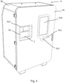
- the collection device 1 preferably comprises a container 9 comprising a frame 90 and an interaction surface 91.
- the container can accommodate the elements presented above, in this case the laying surface 2, the optical recognition device 10 as well as the frame 40, the passage detectors 3, 3', the entry sensors 5 and presence sensors 6, the preview device 7, the projection device 8 when they are present.
- the interaction surface 91 can for example represent a removable protection, such as a lockable door, allowing access to these elements for the purposes of control, adjustment or maintenance. Such a container makes it easy to move the present collection device to make it available for cultural events.
- the interaction surface 91 has an opening opposite the window 43, allowing an object to be placed on the placement surface 2, at level of the drop-off site.
- the opening may be provided with indicators 913 such as indicator lights of different colors to indicate the availability of the collection device.
- the shape or dimensions of the opening are not specific to a deposited item. In other words, a wide variety of different deposited items can be deposited through the opening, as well as a set of several deposited items such as cups, plates, dishes, etc.
- the opening may thus be rectangular, or square or circular. A red light may for example mean that the collection device is malfunctioning and a green light its proper operation.
- a red light may indicate that the integrity and/or cleanliness of the deposited object, determined by the preview device 7, are not correct and that collection of the object will not be initiated.
- the interaction surface 91 may include a digital display screen. Such a display screen may be touch-sensitive or may be accompanied by a numeric keypad (not shown) for selecting items from a menu. Messages may be presented to the user, in particular relating to the acceptance or refusal of the object that he has deposited.
- the present device further comprises at least one means of reimbursing the customer who has returned one or more deposited items.
- the interaction surface 91 may comprise for this purpose a contactless electronic reader 912 such as an RFID reader or any equivalent, making it possible to interact with a smart card, a connected watch, a telephone or an appropriate badge. The amount corresponding to the deposit can then be credited there.
- the interaction surface 91 may comprise a coin mechanism 911 making it possible to distribute the coins corresponding to the deposit. Other means of reimbursement may be envisaged.
- the container 9 may comprise other elements such as one or more storage bins 92, making it possible to group the collected consigned elements D1, D2, D3...Dn .
- the consigned elements D1, D2, D3...Dn are grouped by type after their recognition by the optical recognition device 10, so as to facilitate their handling.
- the consigned element(s) may be directly directed into a storage bin 92 after their recognition and acceptance.
- the laying surface is a conveyor, it may convey the consigned elements directly into a bin.
- the collection device may comprise one or more sorting elements for effectively collecting the accepted consigned elements.
- a sorting element may consist of a conveying element 21 ( figure 1 ), allowing the transfer of the recognized consigned elements from the laying surface 2 to the storage bin 92.
- Such a conveying element can for example convey the consigned element(s) in a direction Y different from the direction X taken by the laying surface 2.
- the sorting element can comprise a brush or a pusher element chasing the consigned element out of the laying surface 2 towards the storage bin 92.
- the consigned element can be chased into a storage bin if it is accepted or left on the conveyor until its return to the deposit site.
- a combination of several sorting elements can be envisaged, in particular in the case where the consigned elements are grouped by type in different storage bins 92.
- several conveying elements 21 can be provided with a system for switching the accepted consigned elements. In this case, it is preferable to place the recorded elements D1, D2, D3...Dn one by one or already grouped by type on the placement surface 2.
- the storage bin(s ) 92 are compatible with a washing machine. According to one embodiment, the collected consigned items are stored in one or more storage bins 92 so that they can be washed directly.
- the device described here also makes it possible to count the accepted consigned elements D1, D2, D3...Dn . It can also count the consigned elements not accepted due to deterioration or dirt.
- the stocks of consigned elements D1, D2, D3...Dn can thus be monitored in real time.
- the collection device 1 can send a message to the operator of the consigned elements.
- the present invention further covers a method or process for managing consigned elements D1, D2, D3...Dn.
- the method comprises in this case a step of depositing one or more consigned elements D1, D2, D3...Dn on a placing surface 2.
- the method may comprise a step of previewing the consigned element(s) by means of the preview device 7 described here and proceeding to the subsequent steps or refusing to proceed to the subsequent steps.
- the method may comprise a step of materializing one or more locations 20 where to deposit the consigned element(s).
- the method may comprise one or more steps of detecting the depositing or removal of an object on the placing surface 2, in particular by means of an entry detector 5.
- the method comprises a step of optical recognition of the deposited recorded element(s), in particular by means of the optical recognition device 7 described above.
- the method may comprise a prior step of detecting the passage of one or more recorded elements towards the detection field 110, in particular by means of one or more passage detectors.
- the method may comprise the detection of the passage of the recorded element(s) beyond the detection field 110.
- the method may comprise a step of comparing the recorded elements as they pass in front of several passage detectors 3, 3'.
- the method includes a step of accepting or rejecting the recorded element(s) as they pass through the detection field 110. Acceptance or rejection is carried out according to the methods set out above, in particular with the contribution of an image processing module and/or artificial intelligence. Such elements may be included in, integrated into, or connected to the optical recognition device 10. Alternatively, the refusal step may occur before the presentation of the element(s) recorded in the detection field.
- the method comprises a step of returning the refused consigned item(s) to the drop-off site or transferring the accepted consigned item(s) to a storage bin 92.
- the method comprises a step of reimbursing a user following the collection of one or more recognised and accepted consigned items, in particular by means of a coin acceptor or a digital reader described above.
- the method may comprise a step of counting the accepted and collected and/or refused consigned items.
- the method may comprise a step of storing the images of the consigned items in databases, in particular for learning and/or image processing purposes.
- the items to be returned are described herein as exemplary items of tableware.
- the items to be returned are not, however, limited to such items of tableware.
- the device and method may be applied to other items requiring return such as items returned and examined after a rental period and for which a deposit may be refunded rather than a deposit, or loan items.
- upstream and downstream apply to the direction of movement of the recorded elements in the X direction of their restitution.
Landscapes
- Physics & Mathematics (AREA)
- General Physics & Mathematics (AREA)
- Geophysics And Detection Of Objects (AREA)
Applications Claiming Priority (1)
| Application Number | Priority Date | Filing Date | Title |
|---|---|---|---|
| CH000867/2023A CH721030A2 (fr) | 2023-08-15 | 2023-08-15 | Dispositif de reconnaissance et de collecte d'éléments consignés |
Publications (1)
| Publication Number | Publication Date |
|---|---|
| EP4510095A1 true EP4510095A1 (de) | 2025-02-19 |
Family
ID=94322772
Family Applications (1)
| Application Number | Title | Priority Date | Filing Date |
|---|---|---|---|
| EP24194448.7A Pending EP4510095A1 (de) | 2023-08-15 | 2024-08-14 | Vorrichtung zum sammeln von pfandobjekten |
Country Status (2)
| Country | Link |
|---|---|
| EP (1) | EP4510095A1 (de) |
| CH (1) | CH721030A2 (de) |
Families Citing this family (1)
| Publication number | Priority date | Publication date | Assignee | Title |
|---|---|---|---|---|
| CN117131449B (zh) * | 2023-08-28 | 2026-04-03 | 烟台海颐软件股份有限公司 | 面向数据治理的具有传播学习能力的异常识别方法及系统 |
Citations (3)
| Publication number | Priority date | Publication date | Assignee | Title |
|---|---|---|---|---|
| FR3070613A1 (fr) * | 2017-09-05 | 2019-03-08 | Matthiessen Engineering Sarl | Dispositif pour la reprise de materiaux en vrac en grande surface de vente ou dans des points de reprise accessibles au public, par exemple pour des cartons, des livres d'autres dechets propres. |
| US20190108502A1 (en) * | 2016-02-02 | 2019-04-11 | Walmart Apollo, Llc | Self-Deposit Apparatus |
| WO2021156228A1 (fr) * | 2020-02-04 | 2021-08-12 | Pellenc Selective Technologies | Dispositif de detection et/ou d'inspection d'objets et machine de collecte et/ou de deconsignation le comprenant |
-
2023
- 2023-08-15 CH CH000867/2023A patent/CH721030A2/fr unknown
-
2024
- 2024-08-14 EP EP24194448.7A patent/EP4510095A1/de active Pending
Patent Citations (3)
| Publication number | Priority date | Publication date | Assignee | Title |
|---|---|---|---|---|
| US20190108502A1 (en) * | 2016-02-02 | 2019-04-11 | Walmart Apollo, Llc | Self-Deposit Apparatus |
| FR3070613A1 (fr) * | 2017-09-05 | 2019-03-08 | Matthiessen Engineering Sarl | Dispositif pour la reprise de materiaux en vrac en grande surface de vente ou dans des points de reprise accessibles au public, par exemple pour des cartons, des livres d'autres dechets propres. |
| WO2021156228A1 (fr) * | 2020-02-04 | 2021-08-12 | Pellenc Selective Technologies | Dispositif de detection et/ou d'inspection d'objets et machine de collecte et/ou de deconsignation le comprenant |
Also Published As
| Publication number | Publication date |
|---|---|
| CH721030A2 (fr) | 2025-02-28 |
Similar Documents
| Publication | Publication Date | Title |
|---|---|---|
| JP6063929B2 (ja) | 容器回収機内の特性を読み取るシステムおよび方法 | |
| CA2442737C (fr) | Dispositif et procede d'inspection automatique d'objets defilant en flux sensiblement monocouche | |
| FR2642542A1 (fr) | Systeme video de balayage et de lecture pour codes a barres | |
| EP0034088B1 (de) | Apparat zur Erkennung von Gegenständen, wie z.B. Flaschen | |
| FR2645310A1 (fr) | Procede d'identification d'objets en mouvement, notamment de vehicules, et systemes pour sa mise en oeuvre | |
| EP3963284B1 (de) | Linie zur inspektion von leeren glasbehältern | |
| WO2011138524A1 (fr) | Dispositif et procede d'inspection de plaquettes semi-conductrices en mouvement | |
| EP4510095A1 (de) | Vorrichtung zum sammeln von pfandobjekten | |
| FR3073044A1 (fr) | Procede et dispositif de mesure de dimensions par rayons x, sur des recipients en verre vide defilant en ligne | |
| EP3017398A1 (de) | System zur inspektion eines mindestens durchscheinenden hohlen objekts mit mindestens einer markierung | |
| CA3160743A1 (fr) | Systeme et procede de detection de fraude | |
| FR2700007A1 (fr) | Procédé et dispositif optiques de classification automatique de pastilles cylindriques de combustible nucléaire. | |
| EP3171990B1 (de) | Method for postal sorting into a sorting compartment with counting of the sorted objects | |
| EP2897865B1 (de) | Verfahren und vorrichtung zur automatischen gepaeckaufgabe | |
| EP0301978A1 (de) | Vorrichtung zur Rücknahme eines Gegenstandes, insbesondere eines Bechers aus Kunststoff, gegen Ausgabe eines Gegenwertes, z.B. Geld | |
| US10943425B2 (en) | Device and system for high-speed bottom scanning of barcodes | |
| FR3093659A1 (fr) | Dispositif d’analyse des déchets, de reconnaissance et de tri automatique des emballages boisson | |
| WO2021156228A1 (fr) | Dispositif de detection et/ou d'inspection d'objets et machine de collecte et/ou de deconsignation le comprenant | |
| FR2563340A1 (fr) | Appareil et procede de controle et de tri de recipients en verre | |
| FR2576528A1 (fr) | Procede de traitement pour la segregation d'objets | |
| WO2016120276A1 (fr) | Procédés et dispositifs de détection de la contamination surfacique par des particules évoluant en air libre | |
| WO2001055705A1 (fr) | Installation et procede pour la detection de glacures | |
| ES2546990T3 (es) | Dispositivo para al reciclaje de envases vacíos y procedimiento para la clasificación de envases vacíos con la ayuda de campos luminosos | |
| FR2520267A1 (fr) | Machine pour la deconsignation d'objets tels que des bouteilles | |
| CN116762088A (zh) | 用于产品的真实性检查的系统 |
Legal Events
| Date | Code | Title | Description |
|---|---|---|---|
| PUAI | Public reference made under article 153(3) epc to a published international application that has entered the european phase |
Free format text: ORIGINAL CODE: 0009012 |
|
| STAA | Information on the status of an ep patent application or granted ep patent |
Free format text: STATUS: THE APPLICATION HAS BEEN PUBLISHED |
|
| AK | Designated contracting states |
Kind code of ref document: A1 Designated state(s): AL AT BE BG CH CY CZ DE DK EE ES FI FR GB GR HR HU IE IS IT LI LT LU LV MC ME MK MT NL NO PL PT RO RS SE SI SK SM TR |
|
| STAA | Information on the status of an ep patent application or granted ep patent |
Free format text: STATUS: REQUEST FOR EXAMINATION WAS MADE |
|
| 17P | Request for examination filed |
Effective date: 20250813 |
|
| STAA | Information on the status of an ep patent application or granted ep patent |
Free format text: STATUS: EXAMINATION IS IN PROGRESS |
|
| 17Q | First examination report despatched |
Effective date: 20251119 |