EP4510167A2 - Canon à électrons, dispositif de génération de rayons x et dispositif d'imagerie à rayons x - Google Patents
Canon à électrons, dispositif de génération de rayons x et dispositif d'imagerie à rayons x Download PDFInfo
- Publication number
- EP4510167A2 EP4510167A2 EP24223618.0A EP24223618A EP4510167A2 EP 4510167 A2 EP4510167 A2 EP 4510167A2 EP 24223618 A EP24223618 A EP 24223618A EP 4510167 A2 EP4510167 A2 EP 4510167A2
- Authority
- EP
- European Patent Office
- Prior art keywords
- electrode
- space
- ray generation
- generation apparatus
- outside
- Prior art date
- Legal status (The legal status is an assumption and is not a legal conclusion. Google has not performed a legal analysis and makes no representation as to the accuracy of the status listed.)
- Pending
Links
Images







Classifications
-
- H—ELECTRICITY
- H01—ELECTRIC ELEMENTS
- H01J—ELECTRIC DISCHARGE TUBES OR DISCHARGE LAMPS
- H01J35/00—X-ray tubes
- H01J35/02—Details
- H01J35/04—Electrodes ; Mutual position thereof; Constructional adaptations therefor
- H01J35/06—Cathodes
- H01J35/064—Details of the emitter, e.g. material or structure
-
- G—PHYSICS
- G01—MEASURING; TESTING
- G01N—INVESTIGATING OR ANALYSING MATERIALS BY DETERMINING THEIR CHEMICAL OR PHYSICAL PROPERTIES
- G01N23/00—Investigating or analysing materials by the use of wave or particle radiation, e.g. X-rays or neutrons, not covered by groups G01N3/00 – G01N17/00, G01N21/00 or G01N22/00
- G01N23/02—Investigating or analysing materials by the use of wave or particle radiation, e.g. X-rays or neutrons, not covered by groups G01N3/00 – G01N17/00, G01N21/00 or G01N22/00 by transmitting the radiation through the material
- G01N23/04—Investigating or analysing materials by the use of wave or particle radiation, e.g. X-rays or neutrons, not covered by groups G01N3/00 – G01N17/00, G01N21/00 or G01N22/00 by transmitting the radiation through the material and forming images of the material
-
- H—ELECTRICITY
- H01—ELECTRIC ELEMENTS
- H01J—ELECTRIC DISCHARGE TUBES OR DISCHARGE LAMPS
- H01J1/00—Details of electrodes, of magnetic control means, of screens, or of the mounting or spacing thereof, common to two or more basic types of discharge tubes or lamps
- H01J1/46—Control electrodes, e.g. grid; Auxiliary electrodes
-
- H—ELECTRICITY
- H01—ELECTRIC ELEMENTS
- H01J—ELECTRIC DISCHARGE TUBES OR DISCHARGE LAMPS
- H01J3/00—Details of electron-optical or ion-optical arrangements common to two or more basic types of discharge tubes or lamps
- H01J3/14—Arrangements for focusing or reflecting ray or beam
- H01J3/18—Electrostatic lenses
-
- H—ELECTRICITY
- H01—ELECTRIC ELEMENTS
- H01J—ELECTRIC DISCHARGE TUBES OR DISCHARGE LAMPS
- H01J35/00—X-ray tubes
- H01J35/02—Details
- H01J35/04—Electrodes ; Mutual position thereof; Constructional adaptations therefor
- H01J35/06—Cathodes
- H01J35/066—Details of electron optical components, e.g. cathode cups
-
- H—ELECTRICITY
- H01—ELECTRIC ELEMENTS
- H01J—ELECTRIC DISCHARGE TUBES OR DISCHARGE LAMPS
- H01J35/00—X-ray tubes
- H01J35/02—Details
- H01J35/14—Arrangements for concentrating, focusing, or directing the cathode ray
- H01J35/147—Spot size control
-
- H—ELECTRICITY
- H01—ELECTRIC ELEMENTS
- H01J—ELECTRIC DISCHARGE TUBES OR DISCHARGE LAMPS
- H01J35/00—X-ray tubes
- H01J35/02—Details
- H01J35/16—Vessels; Containers; Shields associated therewith
-
- H—ELECTRICITY
- H01—ELECTRIC ELEMENTS
- H01J—ELECTRIC DISCHARGE TUBES OR DISCHARGE LAMPS
- H01J37/00—Discharge tubes with provision for introducing objects or material to be exposed to the discharge, e.g. for the purpose of examination or processing thereof
- H01J37/02—Details
- H01J37/04—Arrangements of electrodes and associated parts for generating or controlling the discharge, e.g. electron-optical arrangement or ion-optical arrangement
- H01J37/10—Lenses
- H01J37/12—Lenses electrostatic
-
- G—PHYSICS
- G01—MEASURING; TESTING
- G01N—INVESTIGATING OR ANALYSING MATERIALS BY DETERMINING THEIR CHEMICAL OR PHYSICAL PROPERTIES
- G01N2223/00—Investigating materials by wave or particle radiation
- G01N2223/20—Sources of radiation
- G01N2223/204—Sources of radiation source created from radiated target
-
- H—ELECTRICITY
- H01—ELECTRIC ELEMENTS
- H01J—ELECTRIC DISCHARGE TUBES OR DISCHARGE LAMPS
- H01J2235/00—X-ray tubes
- H01J2235/20—Arrangements for controlling gases within the X-ray tube
Definitions
- the present invention relates to an electron gun, an X-ray generation apparatus, and an X-ray imaging apparatus.
- An electron gun is used in, for example, an X-ray generation apparatus that generates X-rays.
- the electron gun can include, for example, an extraction electrode that extracts electrons, and a focusing electrode that focuses the electrons extracted by the extraction electrode.
- PTL 1 describes an X-ray tube incorporating an electron gun.
- the X-ray tube described in PTL 1 includes a cathode, a target, a first control grid arranged between the cathode and the target, and a second control grid arranged between the first control grid and the target.
- the cathode, the first control grid, and the second control grid are understood as the constituent elements of the electron gun.
- the second control grid includes an opening limiting element. When the opening limiting element is provided, a small beam dimension can be obtained.
- a space where the movement of a gas is limited is formed between the opening limiting element and the cathode.
- a gas can be emitted from the opening limiting element.
- the gas can stay for a long time in the space between the opening limiting element and the cathode. If electrons from the cathode collide against the gas, the gas is ionized. The thus generated ions are accelerated toward the cathode and can collide against the cathode. This can cause degradation of the cathode.
- an electron gun comprising a cathode including an electron emitting portion, an extraction electrode configured to extract electrons emitted from the electron emitting portion, and a focusing electrode configured to focus the electrons extracted by the extraction electrode.
- the focusing electrode includes an outside electrode having a tubular shape, and an inside electrode arranged inside the outside electrode, the inside electrode defines a first space having a columnar shape, and includes a first surface on a side of the cathode, and a second surface on an opposite side of the first surface, and an inside surface of the outside electrode and the second surface of the inside electrode define a second space.
- the inside electrode includes an electron passage hole through which the electrons pass, and a communicating portion configured to make the first space and the second space communicate with each other.
- an X-ray generation apparatus comprises: an electron gun according to the first aspect of the present invention, and an anode including a target configured to generate X-rays when electrons from the electron gun collide.
- an X-ray imaging apparatus comprises: an X-ray generation apparatus according to the second aspect of the present invention; and an X-ray detection apparatus configured to detect X-rays radiated from the X-ray generation apparatus and transmitted through an object.
- Fig. 1 schematically shows the arrangement of an electron gun EG according to the first embodiment of the present invention.
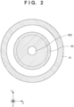
- Fig. 2 shows a section taken along a line B - B' in Fig. 1 .
- Fig. 3 shows the first example of a section taken along a line A - A' in Fig. 1 .
- Fig. 4 shows the second example of the section taken along the line A - A' in Fig. 1 .
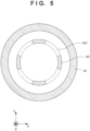
- Fig. 5 shows the third example of the section taken along the line A - A' in Fig. 1 .
- the electron gun EG can be arranged in a vacuum container (not shown) and used.
- the electron gun EG is not limited to a specific application purpose and can be used as a part of an X-ray generation apparatus to be described later, or can be used in other electron beam application apparatuses such as an electron microscope and an electron beam drawing apparatus.
- the electron gun EG can include a cathode 10 including an electron emitting portion that emits electrons, an extraction electrode 30 that extracts the electrons emitted from the electron emitting portion, and a focusing electrode 40 that focuses the electrons extracted by the extraction electrode 30.
- the cathode 10 can include, for example, a filament as the electron emitting portion. The electrons can be emitted when the filament is heated.
- the extraction electrode 30 includes a passage hole 32 through which electrons pass.
- the electron gun EG may include a gate electrode 20 between the cathode 10 and the extraction electrode 30.
- the gate electrode 20 includes a passage hole 22 through which electrons pass.
- the focusing electrode 40 can include an outside electrode 41 having a tubular shape, and an inside electrode 42 arranged inside the outside electrode 41.
- the inside electrode 42 can include an inside surface located on the side of the cathode 10, and an outside surface on the opposite side of the inside surface.
- the inside surface of the inside electrode 42 can include a first inside surface LW1 (first surface) and a second inside surface LW2 having an angle with respect to the first inside surface LW1.
- the outside surface of the inside electrode 42 can include a first outside surface UP1 (second surface) and a second outside surface UP2 located on the opposite side of the second inside surface LW2 and having an angle with respect to the first outside surface UP1.
- a first space SP1 can be defined by the inside surfaces LW1 and LW2 of the inside electrode 42.
- part of the first space SP1 can be defined by the first inside surface LW1 or the second inside surface LW2 of the inside electrode 42.
- (the inside surfaces LW1 and LW2 of) the inside electrode 42 can define the columnar (for example, cylindrical) first space SP1 inside the inside electrode 42.
- a second space SP2 can be defined by the first outside surface UP1 of the inside electrode 42 and an inside surface IS1 of the outside electrode 41.
- a third space SP3 can be defined by the second outside surface UP2 of the inside electrode 42 and the inside surface IS1 of the outside electrode 41.
- the inside electrode 42 can include an electron passage hole 422 through which electrons pass, and a communicating portion 431 that makes the first space SP1 and the third space SP3 communicate with each other.
- the communicating portion 431 makes the inside space (first space SP1) of the inside electrode 42 communicate with the outside spaces (the second space SP2 and the third space SP3) formed by the outside surfaces UP1 and UP2 of the inside electrode 42 and the inside surface IS1 of the outside electrode 41.
- the inside electrode 42 can include a plate portion 421 with the electron passage hole 422, and a tubular portion 43 having a tubular shape. In another viewpoint, one end of the tubular portion 43 can be connected to the plate portion 421.
- the focusing electrode 40 can further include a connecting portion 44 that connects the other end of the tubular portion 43 and the outside electrode 41.
- the connecting portion 44 may be formed by a conductive member, or may be formed by an insulator.
- the communicating portion 431 of the inside electrode 42 can make the first space SP1 communicate with the second space SP2 via the third space SP3.
- the communicating portion 431 can be provided in the tubular portion 43.
- the outside electrode 41 and the inside electrode 42 can be configured to have a coaxial structure with respect to an axis AX.
- the outside electrode 41 can include a cylindrical portion with respect to the axis AX as the center axis.
- the inside electrode 42 can include a cylindrical portion with respect to the axis AX as the center axis.
- the outside electrode 41 can be arranged to surround the side of the inside electrode 42 throughout the perimeter.
- the outside electrode 41 can be arranged to surround the inside electrode 42 throughout the perimeter in any section that is orthogonal to the axis AX and cuts the inside electrode 42.
- the outside electrode 41 can be arranged to surround the communicating portion 431 of the inside electrode 42.
- the outside electrode 41 can be arranged to surround the communicating portion 431 of the inside electrode 42 in any section that is orthogonal to the axis AX and cuts the communicating portion 431 of the inside electrode 42.
- the above-described arrangement is effective to suppress discharge between the inside electrode 42 of the focusing electrode 40 and a member (not shown) that can be arranged outside the focusing electrode 40. This particularly advantageously acts in a case in which the inside electrode 42 includes a portion with a small radius of curvature (a portion with a large curvature) that can induce discharge.
- the first space SP1 can be defined by the extraction electrode 30 in addition to the inside electrode 42.
- the first space SP1 is not a closed space and communicates with the second space SP2 via the electron passage hole 422 and the communicating portion 431.
- the first space SP1 communicates with the space on the side of the cathode 10 via the passage hole 32.
- the outside electrode 41 and the inside electrode 42 are electrically connected to each other and can be given the same potential.
- the outside electrode 41, the inside electrode 42, and the connecting portion 44 are electrically connected to each other and can be given the same potential.
- the extraction electrode 30 may electrically be connected to the inside electrode 42, or may electrically be insulated from the inside electrode 42 and given a potential different from a potential given to the inside electrode 42.
- the extraction electrode 30 is fixed to the focusing electrode 40.
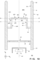
- Fig. 10 shows a modification of the first embodiment.
- the extraction electrode 30 is supported by the focusing electrode 40 (outside electrode 41) via an insulator 39.
- the plate portion 421 provided in the inside electrode 42 of the focusing electrode 40 limits the diameter of an electron beam reaching the second space SP2. Only electrons that have passed through the electron passage hole 422 provided in the plate portion 421 form the electron beam reaching the second space SP2. The remaining electrons collide against the plate portion 421 and are absorbed by the plate portion 421.
- the plate portion 421 including the electron passage hole 422 is provided in the inside electrode 42, the electron beam emitted from the electron gun EG can be focused to a smaller region.
- the communicating portion 431 that makes the first space SP1 and the second space SP2 communicate is provided in the inside electrode 42.
- the communicating portion 431 can be arranged at a position where the electrons do not become incident on it or at a position where the possibility of incidence of the electrons is low. In another viewpoint, the communicating portion 431 can be arranged at a position where the electrons do not pass.
- the communicating portion 431 allows the gas that can be generated in the first space SP1 to be quickly discharged from the first space SP1 to the second space SP2. This functions to suppress degradation of the cathode 10.
- the focusing electrode 40 may be formed such that a linear path via the communicating portion 431 exists between the inside surface IS1 of the outside electrode 41 and a region of the plate portion 421 where the electrons can collide.
- the focusing electrode 40 may be formed such that a linear path via the communicating portion 431 exists between the electron passage hole 422 provided in the plate portion 421 and the inside surface IS1 of the outside electrode 41.
- Such an arrangement allows the gas that can be generated by the collision of electrons against the plate portion 421 to be quickly discharged to the second space SP2 (or the third space SP3).
- a plurality of communicating portions 431 can be provided in the inside electrode 42.
- a single communicating portion 431 may be provided in the inside electrode 42.
- the ratio of the area of the communicating portion 431 to the area of the inside electrode 42 (the portion other than the communicating portion 431) can arbitrarily be determined.
- the influence of the existence of the communicating portion 431 on the function of focusing the electrons from the cathode 10 is small.
- the area of the communicating portion 431 can be made larger than the area of the inside electrode 42 (the portion other than the communicating portion 431). This is advantageous in quickly discharging the gas from the first space SP1 to the second space SP2.
- the outside electrode 41 includes a first end E1 on the side of the electron emitting portion of the cathode 10, and a second end E2 on the opposite side of the first end E1.
- the second end E2 can be formed not to have any angular portion. Such an arrangement is effective to suppress discharge between the outside electrode 41 and a member that can be arranged outside it.
- Fig. 6 schematically shows the arrangement of an electron gun EG according to the second embodiment of the present invention. Matters that are not mentioned as the second embodiment can comply with the first embodiment.
- a first space SP1 and a second space SP2 directly communicate by a communicating portion 431.
- the communicating portion 431 forms a curved discharge path in a section parallel to an axis AX.
- the communicating portion 431 forms a discharge path that is neither parallel nor perpendicular to the axis AX in the section parallel to the axis AX.
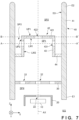
- Fig. 7 schematically shows the arrangement of an electron gun EG according to the third embodiment of the present invention. Matters that are not mentioned as the third embodiment can comply with the first or second embodiment.
- an extraction electrode 30 defines part of a first space SP1.
- the extraction electrode 30 separates the first space SP1 from a fourth space SP4 on the side of a cathode 10.
- the extraction electrode 30 includes not only a passage hole 32 through which electrons pass but also a through hole 33 arranged apart from the passage hole 32.
- the through hole 33 allows a gas that can be generated by collision of the electrons against a plate portion 421 to be discharged to the fourth space SP4.
- the minimum distance between the passage hole 32 and the through hole 33 is preferably five times or more of the radius of the through hole 33.
- the minimum distance between the passage hole 32 and the through hole 33 is preferably 50 times or less of the radius of the through hole 33.
- the extraction electrode 30 can include a plurality of through holes 33.
- the plurality of through holes 33 can be arranged rotation-symmetrically with respect to an axis AX.
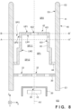
- Fig. 8 schematically shows the arrangement of an electron gun EG according to the fourth embodiment of the present invention. Matters that are not mentioned as the fourth embodiment can comply with each of the first to third embodiments or a combination of two of them.
- a first space SP1 includes a first portion SP11 and a second portion SP12 between the first portion SP11 and an extraction electrode 30.
- the first portion SP11 and the second portion SP12 can be discriminated from each other by the dimension in a direction orthogonal to an axis AX of a focusing electrode 40.
- the dimension of the second portion SP 12 in the direction orthogonal to the axis AX of the focusing electrode 40 is larger than the dimension of the first portion SP11 in the direction orthogonal to the axis AX.
- an inside electrode 42 that defines the second portion SP12 is spaced apart from an outside electrode 41 in Fig. 8 , but may be in contact with the outside electrode 41. This arrangement is advantageous in increasing the distance between a through hole 33 and a passage hole 32.
- Fig. 9 schematically shows the arrangement of an electron gun EG according to the fifth embodiment of the present invention. Matters that are not mentioned as the fifth embodiment can comply with each of the first to fourth embodiments or a combination of two or more of them.
- a first space SP1 includes a first portion SP11 and a second portion SP12 between the first portion SP11 and an extraction electrode 30.
- the first portion SP11 and the second portion SP12 can be discriminated from each other by the dimension in a direction orthogonal to an axis AX of a focusing electrode 40.
- the dimension of the second portion SP 12 in the direction orthogonal to the axis AX of the focusing electrode 40 is larger than the dimension of the first portion SP11 in the direction orthogonal to the axis AX.
- the dimension of the second portion SP 12 in the direction orthogonal to the axis AX of the focusing electrode 40 becomes large toward the side of a cathode 10. This arrangement is advantageous in increasing the distance between a through hole 33 and a passage hole 32.
- Fig. 11 schematically shows the arrangement of an X-ray generation tube 1 according to an embodiment of the present invention.
- the X-ray generation tube 1 can include an electron gun EG according to any one of the first to fifth embodiments, and an anode 93 including a target 933 that generates X-rays when electrons from the electron gun EG collide.
- the X-ray generation tube 1 includes a cathode 91, and the cathode 91 can be electrically connected to a cathode 10 of the electron gun EG.
- the X-ray generation tube 1 includes an insulating tube 92.
- the anode 93 can be arranged to close one of the two opening ends of the insulating tube 92, and the cathode 91 can be arranged to close the other of the two opening ends of the insulating tube 92.
- the anode 93 can include the target 933, a target holding plate 932 that holds the target 933, and an electrode 931 that holds the target holding plate 932.
- the electrode 931 is electrically connected to the target 933 and gives a potential to the target 933.
- the target 933 generates X-rays when electrons from the electron gun EG collide against the target 933.
- the generated X-rays are transmitted through the target holding plate 932 and radiated to the outside of the X-ray generation tube 1.
- the anode 93 can be maintained at, for example, the ground potential but may be maintained at another potential.
- the target 933 can be made of a material having a high melting point and a high X-ray generation efficiency, for example, tungsten, tantalum, or molybdenum.
- the target holding plate 932 can be made of, for example, a conductive material through which X-rays pass, for example, beryllium, diamond, or the like.
- Fig. 12 shows the arrangement of an X-ray generation apparatus 100 according to an embodiment of the present invention.
- the X-ray generation apparatus 100 can include the above-described X-ray generation tube 1, and a driving circuit 3 that drives the X-ray generation tube 1.
- the X-ray generation apparatus 100 can further include a boosting circuit 2 that supplies a boosted voltage to the driving circuit 3.
- the X-ray generation apparatus 100 can further include a storage container 4 that stores the X-ray generation tube 1, the driving circuit 3, and the boosting circuit 2.
- the storage container 4 can be filled with insulating oil.
- Fig. 13 shows the arrangement of an X-ray imaging apparatus 200 according to an embodiment of the present invention.
- the X-ray imaging apparatus 200 can include the X-ray generation apparatus 100, and an X-ray detection apparatus 110 that detects X-rays 104 radiated from the X-ray generation apparatus 100 and transmitted through an object 106.
- the X-ray imaging apparatus 200 may further include a control apparatus 120 and a display apparatus 130.
- the X-ray detection apparatus 110 can include an X-ray detector 112 and a signal processing unit 114.
- the control apparatus 120 can control the X-ray generation apparatus 100 and the X-ray detection apparatus 110.
- the X-ray detector 112 detects or captures the X-rays 104 radiated from the X-ray generation apparatus 100 and transmitted through the object 106.
- the signal processing unit 114 can process a signal output from the X-ray detector 112 and supply the processed signal to the control apparatus 120.
- the control apparatus 120 causes the display apparatus 130 to display an image based on the signal supplied from the signal processing unit 114.
Landscapes
- Chemical & Material Sciences (AREA)
- Analytical Chemistry (AREA)
- Physics & Mathematics (AREA)
- Health & Medical Sciences (AREA)
- Life Sciences & Earth Sciences (AREA)
- Biochemistry (AREA)
- General Health & Medical Sciences (AREA)
- General Physics & Mathematics (AREA)
- Immunology (AREA)
- Pathology (AREA)
- X-Ray Techniques (AREA)
- Electron Sources, Ion Sources (AREA)
Priority Applications (1)
| Application Number | Priority Date | Filing Date | Title |
|---|---|---|---|
| EP24223618.0A EP4510167A3 (fr) | 2018-12-28 | 2018-12-28 | Canon à électrons, dispositif de génération de rayons x et dispositif d'imagerie à rayons x |
Applications Claiming Priority (3)
| Application Number | Priority Date | Filing Date | Title |
|---|---|---|---|
| PCT/JP2018/048608 WO2020136912A1 (fr) | 2018-12-28 | 2018-12-28 | Canon à électrons, dispositif de génération de rayons x, et dispositif d'imagerie par rayons x |
| EP18944979.6A EP3905299A4 (fr) | 2018-12-28 | 2018-12-28 | Canon à électrons, dispositif de génération de rayons x, et dispositif d'imagerie par rayons x |
| EP24223618.0A EP4510167A3 (fr) | 2018-12-28 | 2018-12-28 | Canon à électrons, dispositif de génération de rayons x et dispositif d'imagerie à rayons x |
Related Parent Applications (1)
| Application Number | Title | Priority Date | Filing Date |
|---|---|---|---|
| EP18944979.6A Division EP3905299A4 (fr) | 2018-12-28 | 2018-12-28 | Canon à électrons, dispositif de génération de rayons x, et dispositif d'imagerie par rayons x |
Publications (2)
| Publication Number | Publication Date |
|---|---|
| EP4510167A2 true EP4510167A2 (fr) | 2025-02-19 |
| EP4510167A3 EP4510167A3 (fr) | 2026-04-15 |
Family
ID=67844745
Family Applications (2)
| Application Number | Title | Priority Date | Filing Date |
|---|---|---|---|
| EP24223618.0A Pending EP4510167A3 (fr) | 2018-12-28 | 2018-12-28 | Canon à électrons, dispositif de génération de rayons x et dispositif d'imagerie à rayons x |
| EP18944979.6A Withdrawn EP3905299A4 (fr) | 2018-12-28 | 2018-12-28 | Canon à électrons, dispositif de génération de rayons x, et dispositif d'imagerie par rayons x |
Family Applications After (1)
| Application Number | Title | Priority Date | Filing Date |
|---|---|---|---|
| EP18944979.6A Withdrawn EP3905299A4 (fr) | 2018-12-28 | 2018-12-28 | Canon à électrons, dispositif de génération de rayons x, et dispositif d'imagerie par rayons x |
Country Status (7)
| Country | Link |
|---|---|
| US (1) | US10971322B2 (fr) |
| EP (2) | EP4510167A3 (fr) |
| JP (1) | JP6571907B1 (fr) |
| KR (1) | KR102361378B1 (fr) |
| CN (1) | CN113316833B (fr) |
| TW (1) | TWI730553B (fr) |
| WO (1) | WO2020136912A1 (fr) |
Families Citing this family (2)
| Publication number | Priority date | Publication date | Assignee | Title |
|---|---|---|---|---|
| KR102361378B1 (ko) | 2018-12-28 | 2022-02-09 | 캐논 아네르바 가부시키가이샤 | 전자총, x선 발생 장치 및 x선 촬상 장치 |
| CN114008733B (zh) * | 2019-06-24 | 2022-10-28 | 佳能安内华股份有限公司 | X射线产生管、x射线产生装置以及x射线成像装置 |
Citations (2)
| Publication number | Priority date | Publication date | Assignee | Title |
|---|---|---|---|---|
| JP2007265917A (ja) | 2006-03-29 | 2007-10-11 | Toshiba Corp | X線管及びその制御方法 |
| EP3905299A1 (fr) | 2018-12-28 | 2021-11-03 | Canon Anelva Corporation | Canon à électrons, dispositif de génération de rayons x, et dispositif d'imagerie par rayons x |
Family Cites Families (33)
| Publication number | Priority date | Publication date | Assignee | Title |
|---|---|---|---|---|
| US4091311A (en) * | 1976-12-17 | 1978-05-23 | United Technologies Corporation | Modulatable, hollow beam electron gun |
| US5834781A (en) * | 1996-02-14 | 1998-11-10 | Hitachi, Ltd. | Electron source and electron beam-emitting apparatus equipped with same |
| WO2000003412A1 (fr) * | 1998-07-09 | 2000-01-20 | Hamamatsu Photonics K.K. | Tube a rayons x |
| JP4230016B2 (ja) * | 1998-07-30 | 2009-02-25 | 浜松ホトニクス株式会社 | X線管 |
| JP4230565B2 (ja) * | 1998-07-09 | 2009-02-25 | 浜松ホトニクス株式会社 | X線管 |
| WO2000034977A1 (fr) * | 1998-12-04 | 2000-06-15 | Hitachi, Ltd. | Canon a electrons et tube a rayons cathodiques equipe de celui-ci |
| US7382862B2 (en) * | 2005-09-30 | 2008-06-03 | Moxtek, Inc. | X-ray tube cathode with reduced unintended electrical field emission |
| US9257257B2 (en) * | 2006-06-30 | 2016-02-09 | Shimadzu Corporation | Electron beam control method, electron beam generating apparatus, apparatus using the same, and emitter |
| US7801277B2 (en) * | 2008-03-26 | 2010-09-21 | General Electric Company | Field emitter based electron source with minimized beam emittance growth |
| US8498380B2 (en) * | 2008-11-26 | 2013-07-30 | Koninklijke Philips N.V. | Auxiliary grid electrode for X-ray tubes |
| JP5370967B2 (ja) * | 2009-12-22 | 2013-12-18 | 株式会社東芝 | X線管 |
| JP2012004060A (ja) * | 2010-06-21 | 2012-01-05 | Toshiba Corp | X線源、その調整装置および調整方法 |
| JP5661432B2 (ja) * | 2010-11-17 | 2015-01-28 | キヤノン株式会社 | X線発生装置 |
| US8942352B2 (en) * | 2011-03-29 | 2015-01-27 | Electronics And Telecommunications Research Institute | Field emission x-ray tube apparatus for facilitating cathode replacement |
| JP5800578B2 (ja) * | 2011-05-31 | 2015-10-28 | キヤノン株式会社 | X線管 |
| KR101823876B1 (ko) * | 2011-07-22 | 2018-01-31 | 한국전자통신연구원 | 스페이서를 이용한 적층형 엑스선관 장치 |
| KR101818681B1 (ko) * | 2011-07-25 | 2018-01-16 | 한국전자통신연구원 | 게터 내장형 전계방출 엑스선관 장치 |
| JP5713832B2 (ja) * | 2011-08-03 | 2015-05-07 | キヤノン株式会社 | 放射線発生装置及びそれを用いた放射線撮影装置 |
| JP5890652B2 (ja) * | 2011-10-28 | 2016-03-22 | 株式会社荏原製作所 | 試料観察装置及び試料観察方法 |
| US8933651B2 (en) * | 2012-11-16 | 2015-01-13 | Vladimir Balakin | Charged particle accelerator magnet apparatus and method of use thereof |
| US9484179B2 (en) * | 2012-12-18 | 2016-11-01 | General Electric Company | X-ray tube with adjustable intensity profile |
| JP2014160547A (ja) * | 2013-02-19 | 2014-09-04 | Canon Inc | 放射線発生管及びそれを用いた放射線撮影システム |
| JP6316019B2 (ja) * | 2013-03-06 | 2018-04-25 | キヤノン株式会社 | X線発生管、該x線発生管を備えたx線発生装置及びx線撮影システム |
| US9159528B2 (en) * | 2013-06-07 | 2015-10-13 | Samsung Electronics Co., Ltd. | Electron beam apparatus |
| US9355806B2 (en) * | 2013-07-18 | 2016-05-31 | Schlumberger Technology Corporation | Cathode assembly for use in a radiation generator |
| US20160254116A1 (en) * | 2014-01-29 | 2016-09-01 | Shimadzu Corporation | Metal electrode, and electron gun, electron tube, and x-ray tube using metal electrode |
| KR102238574B1 (ko) * | 2016-12-07 | 2021-04-12 | 한국전자통신연구원 | 전계 방출 장치 |
| US10438764B2 (en) * | 2016-12-07 | 2019-10-08 | Electronics And Telecommunications Research Institute | Field emission apparatus |
| US10580612B2 (en) * | 2017-01-03 | 2020-03-03 | Electronics And Telecommunications Research Institute | Electron emission source and X-ray generator using the same |
| US10559446B2 (en) * | 2017-02-28 | 2020-02-11 | Electronics And Telecommunication Research Institute | Vacuum closed tube and X-ray source including the same |
| JP6792519B2 (ja) * | 2017-06-07 | 2020-11-25 | 浜松ホトニクス株式会社 | X線発生装置 |
| JP2019003863A (ja) * | 2017-06-16 | 2019-01-10 | 株式会社島津製作所 | 電子ビーム装置、ならびに、これを備えるx線発生装置および走査電子顕微鏡 |
| KR102288924B1 (ko) * | 2017-07-28 | 2021-08-11 | (주) 브이에스아이 | 원통형 엑스선 튜브 및 그 제조 방법 |
-
2018
- 2018-12-28 KR KR1020217019806A patent/KR102361378B1/ko active Active
- 2018-12-28 WO PCT/JP2018/048608 patent/WO2020136912A1/fr not_active Ceased
- 2018-12-28 CN CN201880100506.6A patent/CN113316833B/zh active Active
- 2018-12-28 JP JP2019536613A patent/JP6571907B1/ja active Active
- 2018-12-28 EP EP24223618.0A patent/EP4510167A3/fr active Pending
- 2018-12-28 EP EP18944979.6A patent/EP3905299A4/fr not_active Withdrawn
-
2019
- 2019-12-20 TW TW108146822A patent/TWI730553B/zh active
-
2020
- 2020-05-01 US US16/864,934 patent/US10971322B2/en active Active
Patent Citations (2)
| Publication number | Priority date | Publication date | Assignee | Title |
|---|---|---|---|---|
| JP2007265917A (ja) | 2006-03-29 | 2007-10-11 | Toshiba Corp | X線管及びその制御方法 |
| EP3905299A1 (fr) | 2018-12-28 | 2021-11-03 | Canon Anelva Corporation | Canon à électrons, dispositif de génération de rayons x, et dispositif d'imagerie par rayons x |
Also Published As
| Publication number | Publication date |
|---|---|
| TWI730553B (zh) | 2021-06-11 |
| CN113316833B (zh) | 2022-10-04 |
| KR20210087546A (ko) | 2021-07-12 |
| WO2020136912A1 (fr) | 2020-07-02 |
| KR102361378B1 (ko) | 2022-02-09 |
| EP3905299A1 (fr) | 2021-11-03 |
| JP6571907B1 (ja) | 2019-09-04 |
| EP4510167A3 (fr) | 2026-04-15 |
| US20200258710A1 (en) | 2020-08-13 |
| TW202038279A (zh) | 2020-10-16 |
| EP3905299A4 (fr) | 2022-04-06 |
| JPWO2020136912A1 (ja) | 2021-02-18 |
| US10971322B2 (en) | 2021-04-06 |
| CN113316833A (zh) | 2021-08-27 |
Similar Documents
| Publication | Publication Date | Title |
|---|---|---|
| US10841515B1 (en) | X-ray generation tube, X-ray generation apparatus, and X-ray imaging apparatus | |
| US7526068B2 (en) | X-ray source for materials analysis systems | |
| EP2849202A1 (fr) | Dispositif et procédé de génération de rayons x | |
| EP2006880A1 (fr) | Source de rayons X miniature comprenant un guidage des électrons et / ou des ions | |
| US10971322B2 (en) | Electron gun, X-ray generation apparatus, and X-ray imaging apparatus | |
| EP3394876B1 (fr) | Ensemble cible pour appareil d'émission de rayons x et appareil d'émission de rayons x | |
| US9928985B2 (en) | Robust emitter for minimizing damage from ion bombardment | |
| JP7571249B2 (ja) | 電子銃、x線発生管、x線発生装置およびx線撮影システム | |
| JP7137002B2 (ja) | 電子源、及び荷電粒子線装置 | |
| CN217444331U (zh) | 冷阴极x射线管及x射线发生装置 | |
| JP4091217B2 (ja) | X線管 | |
| US20250266230A1 (en) | X-ray tube | |
| WO1984000079A1 (fr) | Source de rayons x | |
| US12580147B2 (en) | X-ray tube | |
| EP3367418A2 (fr) | Microscope électronique à balayage | |
| KR20150075081A (ko) | X-레이 방사선을 생성하기 위한 장치 | |
| JP2012003836A (ja) | 質量分析装置 |
Legal Events
| Date | Code | Title | Description |
|---|---|---|---|
| PUAI | Public reference made under article 153(3) epc to a published international application that has entered the european phase |
Free format text: ORIGINAL CODE: 0009012 |
|
| STAA | Information on the status of an ep patent application or granted ep patent |
Free format text: STATUS: REQUEST FOR EXAMINATION WAS MADE |
|
| 17P | Request for examination filed |
Effective date: 20241230 |
|
| AC | Divisional application: reference to earlier application |
Ref document number: 3905299 Country of ref document: EP Kind code of ref document: P |
|
| AK | Designated contracting states |
Kind code of ref document: A2 Designated state(s): AL AT BE BG CH CY CZ DE DK EE ES FI FR GB GR HR HU IE IS IT LI LT LU LV MC MK MT NL NO PL PT RO RS SE SI SK SM TR |
|
| REG | Reference to a national code |
Ref country code: DE Ref legal event code: R079 Free format text: PREVIOUS MAIN CLASS: H01J0037120000 Ipc: H01J0001460000 |
|
| RIC1 | Information provided on ipc code assigned before grant |
Ipc: H01J 37/12 20060101ALI20250403BHEP Ipc: H01J 35/16 20060101ALI20250403BHEP Ipc: H01J 3/18 20060101ALI20250403BHEP Ipc: G01N 23/04 20180101ALI20250403BHEP Ipc: H01J 35/14 20060101ALI20250403BHEP Ipc: H01J 1/46 20060101AFI20250403BHEP |
|
| PUAL | Search report despatched |
Free format text: ORIGINAL CODE: 0009013 |
|
| AK | Designated contracting states |
Kind code of ref document: A3 Designated state(s): AL AT BE BG CH CY CZ DE DK EE ES FI FR GB GR HR HU IE IS IT LI LT LU LV MC MK MT NL NO PL PT RO RS SE SI SK SM TR |
|
| RIC1 | Information provided on ipc code assigned before grant |
Ipc: H01J 1/46 20060101AFI20260311BHEP Ipc: H01J 35/14 20060101ALI20260311BHEP Ipc: G01N 23/04 20180101ALI20260311BHEP Ipc: H01J 3/18 20060101ALI20260311BHEP Ipc: H01J 35/16 20060101ALI20260311BHEP Ipc: H01J 37/12 20060101ALI20260311BHEP |