EP4510202A1 - Ensemble électrode, élément de batterie, batterie et dispositif électrique - Google Patents
Ensemble électrode, élément de batterie, batterie et dispositif électrique Download PDFInfo
- Publication number
- EP4510202A1 EP4510202A1 EP23866915.4A EP23866915A EP4510202A1 EP 4510202 A1 EP4510202 A1 EP 4510202A1 EP 23866915 A EP23866915 A EP 23866915A EP 4510202 A1 EP4510202 A1 EP 4510202A1
- Authority
- EP
- European Patent Office
- Prior art keywords
- zone
- anode
- active substance
- electrode plate
- cathode
- Prior art date
- Legal status (The legal status is an assumption and is not a legal conclusion. Google has not performed a legal analysis and makes no representation as to the accuracy of the status listed.)
- Pending
Links
Images


Classifications
-
- H—ELECTRICITY
- H01—ELECTRIC ELEMENTS
- H01M—PROCESSES OR MEANS, e.g. BATTERIES, FOR THE DIRECT CONVERSION OF CHEMICAL ENERGY INTO ELECTRICAL ENERGY
- H01M4/00—Electrodes
- H01M4/02—Electrodes composed of, or comprising, active material
- H01M4/04—Processes of manufacture in general
- H01M4/0402—Methods of deposition of the material
- H01M4/0404—Methods of deposition of the material by coating on electrode collectors
-
- H—ELECTRICITY
- H01—ELECTRIC ELEMENTS
- H01M—PROCESSES OR MEANS, e.g. BATTERIES, FOR THE DIRECT CONVERSION OF CHEMICAL ENERGY INTO ELECTRICAL ENERGY
- H01M4/00—Electrodes
- H01M4/02—Electrodes composed of, or comprising, active material
- H01M4/64—Carriers or collectors
- H01M4/66—Selection of materials
- H01M4/665—Composites
- H01M4/667—Composites in the form of layers, e.g. coatings
-
- H—ELECTRICITY
- H01—ELECTRIC ELEMENTS
- H01M—PROCESSES OR MEANS, e.g. BATTERIES, FOR THE DIRECT CONVERSION OF CHEMICAL ENERGY INTO ELECTRICAL ENERGY
- H01M50/00—Constructional details or processes of manufacture of the non-active parts of electrochemical cells other than fuel cells, e.g. hybrid cells
- H01M50/40—Separators; Membranes; Diaphragms; Spacing elements inside cells
- H01M50/471—Spacing elements inside cells other than separators, membranes or diaphragms; Manufacturing processes thereof
- H01M50/474—Spacing elements inside cells other than separators, membranes or diaphragms; Manufacturing processes thereof characterised by their position inside the cells
-
- H—ELECTRICITY
- H01—ELECTRIC ELEMENTS
- H01M—PROCESSES OR MEANS, e.g. BATTERIES, FOR THE DIRECT CONVERSION OF CHEMICAL ENERGY INTO ELECTRICAL ENERGY
- H01M4/00—Electrodes
- H01M4/02—Electrodes composed of, or comprising, active material
-
- H—ELECTRICITY
- H01—ELECTRIC ELEMENTS
- H01M—PROCESSES OR MEANS, e.g. BATTERIES, FOR THE DIRECT CONVERSION OF CHEMICAL ENERGY INTO ELECTRICAL ENERGY
- H01M4/00—Electrodes
- H01M4/02—Electrodes composed of, or comprising, active material
- H01M4/62—Selection of inactive substances as ingredients for active masses, e.g. binders, fillers
-
- H—ELECTRICITY
- H01—ELECTRIC ELEMENTS
- H01M—PROCESSES OR MEANS, e.g. BATTERIES, FOR THE DIRECT CONVERSION OF CHEMICAL ENERGY INTO ELECTRICAL ENERGY
- H01M4/00—Electrodes
- H01M4/02—Electrodes composed of, or comprising, active material
- H01M4/64—Carriers or collectors
- H01M4/66—Selection of materials
- H01M4/664—Ceramic materials
-
- H—ELECTRICITY
- H01—ELECTRIC ELEMENTS
- H01M—PROCESSES OR MEANS, e.g. BATTERIES, FOR THE DIRECT CONVERSION OF CHEMICAL ENERGY INTO ELECTRICAL ENERGY
- H01M4/00—Electrodes
- H01M4/02—Electrodes composed of, or comprising, active material
- H01M4/64—Carriers or collectors
- H01M4/70—Carriers or collectors characterised by shape or form
-
- H—ELECTRICITY
- H01—ELECTRIC ELEMENTS
- H01M—PROCESSES OR MEANS, e.g. BATTERIES, FOR THE DIRECT CONVERSION OF CHEMICAL ENERGY INTO ELECTRICAL ENERGY
- H01M50/00—Constructional details or processes of manufacture of the non-active parts of electrochemical cells other than fuel cells, e.g. hybrid cells
- H01M50/10—Primary casings; Jackets or wrappings
- H01M50/102—Primary casings; Jackets or wrappings characterised by their shape or physical structure
- H01M50/103—Primary casings; Jackets or wrappings characterised by their shape or physical structure prismatic or rectangular
-
- H—ELECTRICITY
- H01—ELECTRIC ELEMENTS
- H01M—PROCESSES OR MEANS, e.g. BATTERIES, FOR THE DIRECT CONVERSION OF CHEMICAL ENERGY INTO ELECTRICAL ENERGY
- H01M50/00—Constructional details or processes of manufacture of the non-active parts of electrochemical cells other than fuel cells, e.g. hybrid cells
- H01M50/10—Primary casings; Jackets or wrappings
- H01M50/102—Primary casings; Jackets or wrappings characterised by their shape or physical structure
- H01M50/105—Pouches or flexible bags
-
- H—ELECTRICITY
- H01—ELECTRIC ELEMENTS
- H01M—PROCESSES OR MEANS, e.g. BATTERIES, FOR THE DIRECT CONVERSION OF CHEMICAL ENERGY INTO ELECTRICAL ENERGY
- H01M50/00—Constructional details or processes of manufacture of the non-active parts of electrochemical cells other than fuel cells, e.g. hybrid cells
- H01M50/10—Primary casings; Jackets or wrappings
- H01M50/147—Lids or covers
- H01M50/148—Lids or covers characterised by their shape
- H01M50/15—Lids or covers characterised by their shape for prismatic or rectangular cells
-
- H—ELECTRICITY
- H01—ELECTRIC ELEMENTS
- H01M—PROCESSES OR MEANS, e.g. BATTERIES, FOR THE DIRECT CONVERSION OF CHEMICAL ENERGY INTO ELECTRICAL ENERGY
- H01M50/00—Constructional details or processes of manufacture of the non-active parts of electrochemical cells other than fuel cells, e.g. hybrid cells
- H01M50/50—Current conducting connections for cells or batteries
- H01M50/572—Means for preventing undesired use or discharge
- H01M50/584—Means for preventing undesired use or discharge for preventing incorrect connections inside or outside the batteries
- H01M50/586—Means for preventing undesired use or discharge for preventing incorrect connections inside or outside the batteries inside the batteries, e.g. incorrect connections of electrodes
-
- H—ELECTRICITY
- H01—ELECTRIC ELEMENTS
- H01M—PROCESSES OR MEANS, e.g. BATTERIES, FOR THE DIRECT CONVERSION OF CHEMICAL ENERGY INTO ELECTRICAL ENERGY
- H01M50/00—Constructional details or processes of manufacture of the non-active parts of electrochemical cells other than fuel cells, e.g. hybrid cells
- H01M50/50—Current conducting connections for cells or batteries
- H01M50/572—Means for preventing undesired use or discharge
- H01M50/584—Means for preventing undesired use or discharge for preventing incorrect connections inside or outside the batteries
- H01M50/59—Means for preventing undesired use or discharge for preventing incorrect connections inside or outside the batteries characterised by the protection means
-
- B—PERFORMING OPERATIONS; TRANSPORTING
- B60—VEHICLES IN GENERAL
- B60L—PROPULSION OF ELECTRICALLY-PROPELLED VEHICLES; SUPPLYING ELECTRIC POWER FOR AUXILIARY EQUIPMENT OF ELECTRICALLY-PROPELLED VEHICLES; ELECTRODYNAMIC BRAKE SYSTEMS FOR VEHICLES IN GENERAL; MAGNETIC SUSPENSION OR LEVITATION FOR VEHICLES; MONITORING OPERATING VARIABLES OF ELECTRICALLY-PROPELLED VEHICLES; ELECTRIC SAFETY DEVICES FOR ELECTRICALLY-PROPELLED VEHICLES
- B60L50/00—Electric propulsion with power supplied within the vehicle
- B60L50/50—Electric propulsion with power supplied within the vehicle using propulsion power supplied by batteries or fuel cells
- B60L50/60—Electric propulsion with power supplied within the vehicle using propulsion power supplied by batteries or fuel cells using power supplied by batteries
- B60L50/64—Constructional details of batteries specially adapted for electric vehicles
-
- H—ELECTRICITY
- H01—ELECTRIC ELEMENTS
- H01M—PROCESSES OR MEANS, e.g. BATTERIES, FOR THE DIRECT CONVERSION OF CHEMICAL ENERGY INTO ELECTRICAL ENERGY
- H01M4/00—Electrodes
- H01M4/02—Electrodes composed of, or comprising, active material
- H01M2004/021—Physical characteristics, e.g. porosity, surface area
-
- H—ELECTRICITY
- H01—ELECTRIC ELEMENTS
- H01M—PROCESSES OR MEANS, e.g. BATTERIES, FOR THE DIRECT CONVERSION OF CHEMICAL ENERGY INTO ELECTRICAL ENERGY
- H01M2220/00—Batteries for particular applications
- H01M2220/20—Batteries in motive systems, e.g. vehicle, ship, plane
-
- Y—GENERAL TAGGING OF NEW TECHNOLOGICAL DEVELOPMENTS; GENERAL TAGGING OF CROSS-SECTIONAL TECHNOLOGIES SPANNING OVER SEVERAL SECTIONS OF THE IPC; TECHNICAL SUBJECTS COVERED BY FORMER USPC CROSS-REFERENCE ART COLLECTIONS [XRACs] AND DIGESTS
- Y02—TECHNOLOGIES OR APPLICATIONS FOR MITIGATION OR ADAPTATION AGAINST CLIMATE CHANGE
- Y02E—REDUCTION OF GREENHOUSE GAS [GHG] EMISSIONS, RELATED TO ENERGY GENERATION, TRANSMISSION OR DISTRIBUTION
- Y02E60/00—Enabling technologies; Technologies with a potential or indirect contribution to GHG emissions mitigation
- Y02E60/10—Energy storage using batteries
-
- Y—GENERAL TAGGING OF NEW TECHNOLOGICAL DEVELOPMENTS; GENERAL TAGGING OF CROSS-SECTIONAL TECHNOLOGIES SPANNING OVER SEVERAL SECTIONS OF THE IPC; TECHNICAL SUBJECTS COVERED BY FORMER USPC CROSS-REFERENCE ART COLLECTIONS [XRACs] AND DIGESTS
- Y02—TECHNOLOGIES OR APPLICATIONS FOR MITIGATION OR ADAPTATION AGAINST CLIMATE CHANGE
- Y02P—CLIMATE CHANGE MITIGATION TECHNOLOGIES IN THE PRODUCTION OR PROCESSING OF GOODS
- Y02P70/00—Climate change mitigation technologies in the production process for final industrial or consumer products
- Y02P70/50—Manufacturing or production processes characterised by the final manufactured product
Definitions
- This application relates to the field of battery technologies, and more specifically to an electrode assembly, a battery cell, a battery, and an electric device.
- Electrode plates are obtained by coating active substances onto current collectors. In electrode cells with wound or stacked electrode plates, electrode plate cracking is often found to varying degrees. Electrode plate cracking is likely to lead to a significant decline in battery performance and even safety hazards.
- this application discloses an electrode assembly, a battery cell, a battery, and an electric device.
- An electrode assembly includes an anode electrode plate and a cathode electrode plate.
- the anode electrode plate includes an anode current collector, at least one side of the anode current collector is coated with an anode active substance layer, and the cathode electrode plate is stacked with the anode electrode plate.
- the cathode electrode plate includes a cathode current collector, at least one side of the cathode current collector is coated with a cathode active substance layer and an additional layer, the additional layer is a non-cathode active substance layer, and an edge of the additional layer is connected to an edge of the cathode active substance layer.
- a projection of the anode active substance layer covers a projection of the cathode active substance layer and partially covers a projection of the additional layer.
- the additional layer connected to an edge of the cathode active substance layer is provided on the cathode current collector, and a projection of the additional layer is made to exceed a projection of the anode active substance layer on a plane perpendicular to the stacking direction of the anode electrode plate and the cathode electrode plate, so that the cathode electrode plate can be prevented from having sharp portions or step portions that would cause shear stress on the anode active substance layer of the anode electrode plate, thereby mitigating or reducing the occurrence of the electrode plate being scratched and cracked.
- the anode current collector has a first edge and a second edge that are disposed opposite each other in a first direction, with an anode tab provided at the first edge; and in the first direction, the additional layer is connected to a side of the cathode active substance layer closer to the anode tab.
- the additional layer is connected to a side of the cathode active substance layer closer to the anode tab, which can mitigate the shear stress generated by the side of the cathode active substance layer closer to the anode tab on the anode active substance layer of the anode electrode plate, thereby mitigating the problem of cracking at that site.
- the cathode active substance layer includes a second flat-coating zone and a second thinning zone that are disposed adjacent to each other.
- the second thinning zone is located on a side of the second flat-coating zone away from the anode tab in the first direction, and a coating thickness of the second thinning zone is less than that of the second flat-coating zone.
- the cathode active substance layer includes a second flat-coating zone and a second thinning zone that are disposed adjacent to each other.
- the second thinning zone reduces the thickness of the cathode active substance layer, which in turn can reduce the height of a step surface formed by the cathode active substance layer at a corresponding edge position, or eliminate the step surface formed by the cathode active substance layer at the corresponding edge position, thereby reducing the shear stress on the anode active substance layer of the anode electrode plate, and mitigating or reducing the shedding of the anode active substance layer at the edge of the anode electrode plate.
- the anode active substance layer includes a first flat-coating zone and a first thinning zone that are disposed adjacent to each other.
- the first thinning zone is located on a side of the first flat-coating zone closer to the anode tab in the first direction, and a coating thickness of the first thinning zone is less than that of the first flat-coating zone.
- the anode active substance layer includes a first flat-coating zone and a first thinning zone that are disposed adjacent to each other, effectively mitigating or reducing the shear stress on the anode active substance layer at the edge of the anode electrode plate.
- the first thinning zone in the first direction, has a width ranging from 1 mm to 30 mm, and the second thinning zone has a width ranging from 1 mm to 30 mm.
- the widths of the first thinning zone and the second thinning zone are in the optimal range, which can reduce shear stress while ensuring that the battery cell has the capacity to meet the requirements.
- the cathode active substance layer further includes a third thinning zone.
- the third thinning zone is located on a side of the second flat-coating zone away from the second thinning zone in the first direction, and a coating thickness of the third thinning zone is less than that of the second flat-coating zone.
- the additional layer includes a fourth thinning zone.
- the fourth thinning zone is smoothly transitioned and connected to the third thinning zone, and a coating thickness of the fourth thinning zone is less than that of the third thinning zone.
- the thickness of the fourth thinning zone of the additional layer is less than that of the third thinning zone, which can further weaken or mitigate the shear stress on the anode active substance layer of the anode electrode plate due to the presence of thick step portions at the connection between the fourth thinning zone and the third thinning zone.
- the projection of the end of the fourth thinning zone away from the third thinning zone is not covered by the projection of the first thinning zone. In this way, it is possible to prevent the end of the fourth thinning zone of the additional layer away from the third thinning zone from generating shear stress on the first thinning zone.
- a fifth thinning zone is formed on at least one of two ends of the cathode active substance layer and/or two ends of the additional layer, and the first direction, the second direction, and the stacking direction of the anode electrode plate and the cathode electrode plate are perpendicular to each other. In this way, the cracking of the anode electrode plate and the cathode electrode plate can be further mitigated.
- the additional layer is a ceramic layer, a resistor layer, or an insulating layer, with a hardness lower than that of the anode active substance layer. In this way, the additional layer with a hardness lower than that of the anode active substance layer can reduce the risk of shear stress generated by the cathode electrode plate on the anode active substance layer of the anode electrode plate.
- the electrode assembly further includes an insulating member, the insulating member being provided between the cathode electrode plate and the anode electrode plate. In this way, the insulating member isolates the anode electrode plate and the cathode electrode plate that are adjacent, preventing the two adjacent electrode plates with opposite polarities from contacting and causing a short circuit.
- a battery cell includes a housing, an electrode assembly, and the foregoing end cover assembly.
- the housing has an opening, the end cover assembly covers the opening, and the electrode assembly is accommodated in the housing.
- the foregoing battery cell reduces the risk of electrode plate cracking in the electrode assembly and ensures that the battery cell has the capacity to meet the requirements of use.
- a battery includes a box and the foregoing battery cells, where the battery cells are arranged in the box.
- the battery cells are highly safety and have large capacity.
- An electric device includes the foregoing battery cells, the battery cells being configured to supply electrical energy, or includes the foregoing battery, the battery being configured to supply electrical energy.
- the battery has a long battery life.
- first and second are merely for the purpose of description and shall not be understood as any indication or implication of relative importance or any implicit indication of the number of the technical features indicated. Therefore, a feature limited by the term “first”, “second”, or the like can explicitly or implicitly include one or more such features.
- a plurality of means at least two, for example, two or three, unless otherwise specifically stated.
- the terms “mounting”, “connection”, “join”, and “fastening” should be understood in their general senses. For example, they may refer to a fixed connection, a detachable connection, or an integral connection, may refer to a mechanical connection or electrical connection, and may refer to a direct connection, an indirect connection via an intermediate medium, an internal communication between two elements, or an interaction between two elements, unless otherwise specifically stated. Persons of ordinary skills in the art can understand specific meanings of these terms in this application as appropriate to specific situations.
- the first feature being “above” or “below” the second feature may mean that the first feature is in direct contact with the second feature or may mean that the first feature and the second feature come into contact indirectly through an intermediary.
- the first feature is “above”, “over”, and “on” the second feature may mean that the first feature is directly above or obliquely above the second feature or simply mean that the first feature has a higher level than the second feature.
- That the first feature is "below”, “beneath”, and “under” the second feature may mean that the first feature is directly below or obliquely below the second feature or simply mean that the first feature has a lower level than the second feature.
- Electric vehicle batteries are rechargeable batteries that serve as power source for new energy vehicles and are widely used in the field of new energy vehicles.
- the anode electrode plate, cathode electrode plate, and separator are typically wound or stacked, followed by processes like hot pressing.
- electrode plates are obtained by coating active substances onto current collectors.
- electrode plate cracking is often found to varying degrees. electrode plate cracking is likely to lead to a significant decline in battery performance and even safety hazards.
- an electrode assembly, a battery cell, a battery, and an electric device have been designed.
- an additional layer connected to an edge of a cathode active substance layer is provided on a cathode current collector, and a projection of the additional layer is made to exceed a projection of an anode active substance layer on a plane perpendicular to a stacking direction of an anode electrode plate and an cathode electrode plate, so that the cathode electrode plate can be prevented from having sharp portions or step portions that would cause shear stress on the anode active substance layer of the anode electrode plate, thereby mitigating or reducing the occurrence of the electrode plate being scratched and cracked.
- An embodiment of this application provides an electric device that uses a battery as a power supply.
- the electric device may be but is not limited to a mobile phone, a tablet, a notebook computer, an electric toy, an electric tool, an electric bicycle, an electric vehicle, a ship, or a spacecraft.
- the electric toy may be a fixed or mobile electric toy, for example, a game console, an electric toy car, an electric toy ship, and an electric toy airplane.
- the spacecraft may include an airplane, a rocket, a space shuttle, a spaceship, and the like.
- the electric device of an embodiment of this application being a vehicle 10 is used as an example for description of the following embodiments.
- FIG. 1 is a schematic structural diagram of the vehicle 10 according to an embodiment of this application.
- the vehicle 10 may be a fossil fuel vehicle, a natural gas vehicle, or a new energy vehicle.
- the new energy vehicle may be a battery electric vehicle, a hybrid electric vehicle, a range-extended electric vehicle, or the like.
- the vehicle 10 is provided with a battery 20 inside, and the battery 20 may be disposed at the bottom, front, or rear of the vehicle 10.
- the battery 20 may be configured to supply power to the vehicle 10.
- the battery 20 may be used as an operational power supply for the vehicle 10.
- the vehicle 10 may further include a controller 11 and a motor 12, where the controller 11 is configured to control the battery 20 to supply power to the motor 12, for example, to satisfy power needs of start, navigation, and driving of the vehicle 10.
- the battery 20 can be used as not only the operational power supply for the vehicle 10 but also a driving power supply for the vehicle 10, replacing or partially replacing fossil fuel or natural gas to provide driving power for the vehicle 10.
- FIG. 2 is an exploded view of a battery 20 according to an embodiment of this application.
- the battery 20 includes a box 21 and battery cells 22, where the battery cells 22 are accommodated in the box 21.
- the box 21 is configured to provide an accommodating space for the battery cell 22.
- the box 21 may be a variety of structures.
- the box 21 may include a first portion 21a and a second portion 21b. The first portion 21a and the second portion 21b fit together to jointly define an accommodating space for accommodating the battery cells 22.
- the second portion 21b may be a hollow structure with an opening at one end
- the first portion 21a may be a plate-shaped structure
- the first portion 21a covers the opening side of the second portion 21b so that the first portion 21a and the second portion 21b jointly define the accommodating space.
- both the first portion 21a and the second portion 21b may be hollow structures with an opening at one side, and the opening side of the first portion 21a is engaged with the opening side of the second portion 21b.
- the box 21 formed by the first portion 21a and the second portion 21b may be of various shapes, for example, cylinder or cuboid.
- the battery cells 22 may be present in plurality, and the plurality of battery cells 22 may be connected in series, parallel, or series-parallel, where being connected in series-parallel means a combination of series and parallel connections of the plurality of battery cells 22.
- the plurality of battery cells 22 may be directly connected in series, parallel, or series-parallel, and then an entirety of the plurality of battery cells 22 is accommodated in the box 21; or certainly, the battery 20 may be formed by a plurality of battery cells 22 being connected in series, parallel, or series-parallel first to form a battery module and then a plurality of battery modules being connected in series, parallel, or series-parallel to form an entirety which is accommodated in the box 21.
- Each battery cell 22 may be a secondary battery or a primary battery, or may be a lithium-sulfur battery, a sodium-ion battery, or a magnesium-ion battery, without being limited thereto.
- the battery cell 22 may be cylindrical, flat, cuboid, or of other shapes.
- the battery cell 22 may include a lithium-ion secondary battery, a lithium-ion primary battery, a lithium-sulfur battery, a sodium-lithium-ion battery, a sodium-ion battery, a magnesium-ion battery, or the like. This is not limited in the embodiments of this application.
- the battery cell 22 may be cylindrical, flat, cuboid, or of other shapes, which is not limited in the embodiments of this application either.
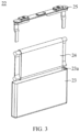
- the battery cell 22 includes a housing 23, an electrode assembly 24, and an end cover assembly 25.
- the housing 23 is a hollow cuboid or cube, and one of the planes of the housing 23 is a plane with an opening 23a, and the plane is configured to have no wall body, so that the inside and outside of the housing 23 are in communication with each other.
- the end cover assembly 25 covers the opening 23a and is connected to the housing 23 to form an enclosed chamber for placing the electrode assembly 24, and the enclosed chamber is filled with an electrolyte, such as an electrolyte solution.
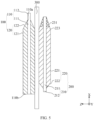
- an electrode assembly 24 in an embodiment includes an anode electrode plate 100 and a cathode electrode plate 200.
- the cathode electrode plate 200 and the anode electrode plate 100 are stacked.
- the anode electrode plate 100 includes an anode current collector 110, and at least one side of the anode current collector 110 is coated with an anode active substance layer 120.
- the cathode electrode plate 200 includes a cathode current collector 210, and at least one side of the cathode current collector 210 is coated with a cathode active substance layer 220 and an additional layer 230.
- the additional layer 230 is a non-cathode active substance layer 220, and an edge of the additional layer 230 is connected to an edge of the cathode active substance layer 220.
- a projection of the anode active substance layer 120 covers a projection of the cathode active substance layer 220 and partially covers a projection of the additional layer 230.
- the stacking direction of the anode electrode plate 100 and the cathode electrode plate 200 is direction Z shown in FIG. 4 , that is, thickness direction of the anode electrode plate 100 and the cathode electrode plate 200.
- an electrode assembly 24 can be formed by winding or stacking an anode electrode plate 100 and a cathode electrode plate 200.
- the anode current collector 110 is a member or part that carries the anode active substance layer 120 and collects and outputs the current generated by an anode active substance.
- the anode active substance includes at least one of lithium nickel cobalt manganese oxide, lithium iron phosphate, lithium nickelate, lithium nickel manganate, lithium manganese iron nickelate, or carbon materials (graphite, hard carbon, soft carbon, carbon nanotubes, or graphene), where graphite includes at least one of artificial graphite, natural graphite, or mesocarbon microbeads.
- the cathode current collector 210 is a member or part that carries the cathode active substance layer 220 and collects and outputs the current generated by a cathode active substance.
- the cathode active substance includes at least one of lithium titanate, silicon negative electrode, silicon-carbon negative electrode, lithium metal negative electrode materials, tin-based negative electrode materials, or tin oxide negative electrode materials.
- the additional layer 230 connected to an edge of the cathode active substance layer 220 is provided on the cathode current collector 210, and a projection of the additional layer 230 is made to exceed a projection of the anode active substance layer 120 on a plane perpendicular to the stacking direction of the anode electrode plate 100 and the cathode electrode plate 200, so that the cathode electrode plate 200 can be prevented from having sharp portions or step portions that would cause shear stress on the anode active substance layer 120 of the anode electrode plate 100, thereby mitigating or reducing the occurrence of the electrode plate being scratched and cracked.
- the anode current collector 110 has a first edge 110a and a second edge 110b that are disposed opposite each other in a first direction, with an anode tab 112 provided at the first edge 110a; and in the first direction, the additional layer 230 is connected to a side of the cathode active substance layer 220 closer to the anode tab 112.
- the first direction is direction X shown in FIG. 4 .
- the anode tab 112 and the anode current collector 110 are formed as an integral structure.
- the anode tab 112 and the anode current collector 110 may alternatively be separate structures, that is, the anode tab 112 is additionally provided at the first edge 110a of the anode current collector 110.
- the additional layer 230 is connected to a side of the cathode active substance layer 220 closer to the anode tab 112, which can mitigate the shear stress generated by the side of the cathode active substance layer 220 closer to the anode tab 112 on the anode active substance layer 120 of the anode electrode plate 100, thereby mitigating the problem of cracking at that site.
- the anode active substance layer 120 includes a first flat-coating zone 121 and a first thinning zone 122 that are disposed adjacent to each other.
- the first thinning zone 122 is located on a side of the first flat-coating zone 121 closer to the anode tab 112 in the first direction, and a coating thickness of the first thinning zone 122 is less than that of the first flat-coating zone 121.
- the thickness of the anode active substance layer 120 of the first thinning zone 122 gradually decreases in a first direction from the first flat-coating zone 121 to the first thinning zone 122, and the thickness of the anode active substance layer 120 of the first flat-coating zone 121 is uniform.
- the anode active substance layer 120 includes the first flat-coating zone 121 and the first thinning zone 122 that are disposed adjacent to each other, effectively mitigating or reducing the shear stress on the anode active substance layer 120 at the edge of the anode electrode plate 100.
- the cathode active substance layer 220 includes a second flat-coating zone 221 and a second thinning zone 222 that are disposed adjacent to each other.
- the second thinning zone 222 is located on a side of the second flat-coating zone 221 away from the anode tab 112 in the first direction, and the coating thickness of the second thinning zone 222 is less than that of the second flat-coating zone 221.
- the thickness of the anode active substance layer 120 of the second thinning zone 222 gradually decreases in the first direction from the second flat-coating zone 221 to the second thinning zone 222, and the thickness of the anode active substance layer 120 of the second flat-coating zone 221 is uniform.
- a cathode tab 212 is provided at an edge of the cathode current collector 210.
- the cathode tab 212 and the anode tab 112 are located on opposite sides in the first direction.
- the cathode tab 212 and the anode tab 112 may alternatively be located on a same side in the first direction.
- the cathode active substance layer 220 includes a second flat-coating zone 221 and a second thinning zone 222 that are disposed adjacent to each other.
- the second thinning zone 222 reduces the thickness of the cathode active substance layer 220, which in turn can reduce the height of a step surface formed by the cathode active substance layer 220 at a corresponding edge position, or eliminate the step surface formed by the cathode active substance layer 220 at the corresponding edge position, thereby reducing the shear stress on the anode active substance layer 120 of the anode electrode plate 100, and mitigating or reducing the shedding of the anode active substance layer 120 at the edge of the anode electrode plate 100.
- the first thinning zone 122 has a width ranging from 1 mm to 30 mm
- the second thinning zone 222 has a width ranging from 1 mm to 30 mm.
- the width direction is direction X shown in FIG. 4
- the widths of the first thinning zone 122 and the second thinning zone 222 are dimensions along the direction X shown in FIG. 4 .
- the widths of the first thinning zone 122 and the second thinning zone 222 are in the optimal range, which can reduce shear stress while ensuring that the battery cell 22 has the capacity to meet the requirements.
- the cathode active substance layer 220 further includes a third thinning zone 223.
- the third thinning zone 223 is located on a side of the second flat-coating zone 221 away from the second thinning zone 222 in the first direction, and a coating thickness of the third thinning zone 223 is less than that of the second flat-coating zone 221.
- the thickness of the cathode active substance layer 220 of the third thinning zone 223 gradually decreases in the first direction from the second flat-coating zone 221 to the third thinning zone 223.
- the third thinning zone 223 and the first thinning zone 122 are located on a same side in the first direction. During winding or stacking the anode electrode plate 100 and the cathode electrode plate 200, there will be compressive stress between the third thinning zone 223 of the cathode electrode plate 200 and the third thinning zone 223 of the anode electrode plate 100.
- the cathode electrode plate 200 can be prevented from having sharp portions or step portions that would cause shear stress on the anode active substance layer 120 of the anode electrode plate 100
- the shear stress by a step portion formed by the cathode active substance layer 220 of the cathode electrode plate 200 at the edge position on the anode active substance layer 120 of the anode electrode plate 100 can be reduced, thereby mitigating the problem of electrode plate cracking.
- the additional layer 230 includes a fourth thinning zone 231.
- the fourth thinning zone 231 is smoothly transitioned and connected to the third thinning zone 223, and a coating thickness of the fourth thinning zone 231 is less than that of the third thinning zone 223.
- the thickness of the additional layer 230 of the fourth thinning zone 231 gradually decreases, and the thickness of the cathode active substance layer 220 of the third thinning zone 223 also gradually decreases.
- the slope of the third thinning zone 223 equals that of the fourth thinning zone 231 to make a smooth transition and connection between the third thinning zone 223 and the fourth thinning zone 231. That is, the minimum thickness of the third thinning zone 223 equals the maximum thickness of the fourth thinning zone 231.
- sharp portions or step portions can be further prevented from appearing at the connection between the fourth thinning zone 231 and the third thinning zone 223 to generate shear stress on the anode electrode plate 100.
- the thickness of the fourth thinning zone 231 of the additional layer 230 is less than the coating thickness of the third thinning zone 223, which can further weaken or mitigate the shear stress on the anode active substance layer 120 of the anode electrode plate 100 due to the presence of thick step portions at the connection between the fourth thinning zone 231 and the third thinning zone 223.
- a projection of an end of the fourth thinning zone 231 away from the third thinning zone 223 is not covered by a projection of the first thinning zone 122.
- the third thinning zone 223 has a width ranging from 1 mm to 30 mm
- the fourth thinning zone 231 has a width ranging from 1 mm to 30 mm. In this way, the shear stress on the cathode electrode plate 200 can be effectively reduced while ensuring that the battery cell 22 has the capacity to meet the requirements.
- a fifth thinning zone is formed on at least one of two ends of the cathode active substance layer 220 and/or two ends of the additional layer 230, and the first direction, the second direction, and the stacking direction of the anode electrode plate 100 and the cathode electrode plate 200 are perpendicular to each other.
- the second direction is direction Y shown in FIG. 5 , that is, length direction of the anode electrode plate 100 and the cathode electrode plate 200.
- the fifth thinning zone is provided on the cathode active substance layer 220 in the second direction, the thickness of the cathode active substance layer 220 of the fifth thinning zone gradually decreases in the second direction.
- the fifth thinning zone is provided on the additional layer 230 in the second direction, the thickness of the additional layer 230 of the fifth thinning zone gradually decreases in the second direction.
- a fifth thinning zone may be provided on the cathode active substance layer 220 and/or the additional layer 230 in the second direction different from the first direction, to further reduce the risk of electrode plate cracking.
- the cracking of the anode electrode plate 100 and the cathode electrode plate 200 can be further mitigated.
- the additional layer 230 is a ceramic layer, a resistor layer, or an insulating layer, with a hardness lower than that of the anode active substance layer 120.
- the additional layer 230 may alternatively be other substances with high resistance and low specific capacity that are different from the first active substance.
- the additional layer 230 with a hardness lower than that of the anode active substance layer 120 can reduce the risk of shear stress generated by the cathode electrode plate 200 on the anode active substance layer 120 of the anode electrode plate 100.
- the electrode assembly 24 further includes an insulating member 300, the insulating member 300 being provided between the cathode electrode plate 200 and the anode electrode plate 100.
- the insulating member 300 is a separator.
- the separator is insulating and used to isolate the anode electrode plate 100 and the cathode electrode plate 200 that are adjacent, preventing the two adjacent electrode plates with opposite polarities from contacting and causing a short circuit.
- the separator may be made of an organic polymer insulating material, an inorganic insulating material, or a composite material.
- the composite material is composed of an organic polymer insulating material and an inorganic insulating material.
- the insulating member 300 isolates the anode electrode plate 100 and the cathode electrode plate 200 that are adjacent, preventing the two adjacent electrode plates with opposite polarities from contacting and causing a short circuit.
- a battery cell 22 in an embodiment includes a housing 23, an end cover assembly 25, and the foregoing electrode assembly 24.
- the housing 23 has an opening 23a, and the end cover assembly 25 covers the opening 23a, with the electrode assembly 24 accommodated in the housing 23.
- the housing 23 is an assembly configured to cooperate with the end cover assembly 25 to form an internal environment of the battery cell 22, where the formed internal environment can be used to accommodate the electrode assembly 24, an electrolyte solution, and other components.
- the housing 23 and the end cover assembly 25 may be independent components, an opening 23a may be formed in the housing 23, and the end cover assembly 25 covers the opening 23a to form the internal environment of the battery cell 22.
- the housing 23 and the end cover assembly 25 are not limited and may also be integrated. Specifically, the housing 23 and the end cover assembly 25 may form a shared connection surface before other components are disposed in the housing, and then the housing 23 is covered with the end cover assembly 25 when inside of the housing 23 needs to be enclosed.
- the housing 23 may be of various shapes and sizes, such as a cuboid shape, a cylindrical shape, and a hexagonal prism shape. Specifically, a shape of the housing 23 may be determined according to a specific shape and size of the electrode assembly 24.
- the housing 23 may be made of various substances, such as copper, iron, aluminum, stainless steel, aluminum alloy, and plastic, which are not particularly limited in the embodiments of this application.
- the foregoing battery cell 22 reduces the risk of electrode plate cracking in the electrode assembly 24 and ensures that the battery cell 22 has the capacity to meet the requirements of use.
- a battery 20 in an embodiment includes a box 21 and the foregoing battery cells 22, the battery cells 22 being arranged in the box 21.
- the battery cells 22 are highly safety and have large capacity.
- an electric device in an embodiment includes the foregoing battery cells 22, the battery cells 22 being configured to supply electrical energy, or includes the foregoing battery 20, the battery 20 being configured to supply electrical energy.
- the battery 20 has a long battery life.
- an electrode assembly 24 in an embodiment includes an anode electrode plate 100, a cathode electrode plate 200, and an insulating member 300.
- the cathode electrode plate 200 and the anode electrode plate 100 are stacked, and the insulating member 300 is provided between the cathode electrode plate 200 and the anode electrode plate 100.
- the anode electrode plate 100 includes an anode current collector 110, and at least one side of the anode current collector 110 is coated with an anode active substance layer 120.
- the cathode electrode plate 200 includes a cathode current collector 210, and at least one side of the cathode current collector 210 is coated with a cathode active substance layer 220 and an additional layer 230.
- the additional layer 230 is a ceramic layer, a resistor layer, or an insulating layer, with a hardness lower than that of the anode active substance layer 120, and an edge of the additional layer 230 is connected to an edge of the cathode active substance layer 220.
- a projection of the anode active substance layer 120 covers a projection of the cathode active substance layer 220 and partially covers a projection of the additional layer 230.
- the anode active substance layer 120 includes a first flat-coating zone 121 and a first thinning zone 122 that are disposed adjacent to each other.
- the first thinning zone 122 is located on a side of the first flat-coating zone 121 closer to the anode tab 112 in the first direction, and a coating thickness of the first thinning zone 122 is less than that of the first flat-coating zone 121.
- the cathode active substance layer 220 includes a second flat-coating zone 221 and a second thinning zone 222 that are disposed adjacent to each other.
- the second thinning zone 222 is located on a side of the second flat-coating zone 221 away from the anode tab 112 in the first direction, and the coating thickness of the second thinning zone 222 is less than that of the second flat-coating zone 221.
- the cathode active substance layer 220 further includes a third thinning zone 223.
- the third thinning zone 223 is located on a side of the second flat-coating zone 221 away from the second thinning zone 222 in the first direction, and a coating thickness of the third thinning zone 223 is less than that of the second flat-coating zone 221.
- the additional layer 230 includes a fourth thinning zone 231.
- the fourth thinning zone 231 is smoothly transitioned and connected to the third thinning zone 223, and a coating thickness of the fourth thinning zone 231 is less than that of the third thinning zone 223.
- a projection of an end of the fourth thinning zone 231 away from the third thinning zone 223 is not covered by a projection of the first thinning zone 122.
- a fifth thinning zone is formed on at least one of two ends of the cathode active substance layer 220 and/or two ends of the additional layer 230.
- a battery cell 22 in an embodiment includes a housing 23, an end cover assembly 25, and the foregoing electrode assembly 24.
- the housing 23 has an opening 23a, and the end cover assembly 25 covers the opening 23a, with the electrode assembly 24 accommodated in the housing 23.
- a battery 20 in an embodiment includes a box 21 and the foregoing battery cells 22, the battery cells 22 being arranged in the box 21.
- an electric device in an embodiment includes the foregoing battery cells 22, the battery cells 22 being configured to supply electrical energy, or includes the foregoing battery 20, the battery 20 being configured to supply electrical energy.
Landscapes
- Chemical & Material Sciences (AREA)
- Chemical Kinetics & Catalysis (AREA)
- Electrochemistry (AREA)
- General Chemical & Material Sciences (AREA)
- Engineering & Computer Science (AREA)
- Manufacturing & Machinery (AREA)
- Materials Engineering (AREA)
- Ceramic Engineering (AREA)
- Composite Materials (AREA)
- Battery Electrode And Active Subsutance (AREA)
- Secondary Cells (AREA)
- Sealing Battery Cases Or Jackets (AREA)
Applications Claiming Priority (2)
| Application Number | Priority Date | Filing Date | Title |
|---|---|---|---|
| CN202211154768.5A CN115275092B (zh) | 2022-09-22 | 2022-09-22 | 电极组件、电池单体、电池及用电设备 |
| PCT/CN2023/090770 WO2024060618A1 (fr) | 2022-09-22 | 2023-04-26 | Ensemble électrode, élément de batterie, batterie et dispositif électrique |
Publications (2)
| Publication Number | Publication Date |
|---|---|
| EP4510202A1 true EP4510202A1 (fr) | 2025-02-19 |
| EP4510202A4 EP4510202A4 (fr) | 2025-11-12 |
Family
ID=83757008
Family Applications (1)
| Application Number | Title | Priority Date | Filing Date |
|---|---|---|---|
| EP23866915.4A Pending EP4510202A4 (fr) | 2022-09-22 | 2023-04-26 | Ensemble électrode, élément de batterie, batterie et dispositif électrique |
Country Status (6)
| Country | Link |
|---|---|
| US (1) | US20250105455A1 (fr) |
| EP (1) | EP4510202A4 (fr) |
| JP (1) | JP2025516735A (fr) |
| KR (1) | KR20250022186A (fr) |
| CN (2) | CN115275092B (fr) |
| WO (1) | WO2024060618A1 (fr) |
Families Citing this family (6)
| Publication number | Priority date | Publication date | Assignee | Title |
|---|---|---|---|---|
| CN115275092B (zh) * | 2022-09-22 | 2023-07-07 | 江苏时代新能源科技有限公司 | 电极组件、电池单体、电池及用电设备 |
| CN118782720A (zh) * | 2023-04-03 | 2024-10-15 | 宁德时代新能源科技股份有限公司 | 电极组件、电池单体、电池和用电装置 |
| CN116454415A (zh) * | 2023-06-20 | 2023-07-18 | 深圳海辰储能控制技术有限公司 | 电极组件、电池和用电设备 |
| CN119601576A (zh) * | 2023-09-08 | 2025-03-11 | 宁德时代新能源科技股份有限公司 | 电池单体、电池、用电装置、阴极极片及其制作方法 |
| CN120453276A (zh) * | 2024-02-07 | 2025-08-08 | 宁德时代新能源科技股份有限公司 | 电极组件、电极组件的制造方法、电池单体、电池和用电装置 |
| CN118970228B (zh) * | 2024-07-31 | 2025-11-28 | 宁德新能源科技有限公司 | 二次电池、用电设备及负极片的制造方法 |
Family Cites Families (17)
| Publication number | Priority date | Publication date | Assignee | Title |
|---|---|---|---|---|
| JPH10241725A (ja) * | 1997-02-28 | 1998-09-11 | Sanyo Electric Co Ltd | アルカリ二次電池 |
| JP4617065B2 (ja) * | 2002-05-30 | 2011-01-19 | パナソニック株式会社 | リチウムイオン二次電池 |
| JP4359099B2 (ja) * | 2003-08-04 | 2009-11-04 | 三洋電機株式会社 | 円筒型アルカリ蓄電池 |
| CN103280603B (zh) * | 2013-06-03 | 2015-11-18 | 深圳市量能科技有限公司 | 一种高容量镍氢电池及其制作方法 |
| JP2015125893A (ja) * | 2013-12-26 | 2015-07-06 | トヨタ自動車株式会社 | 全固体電池の製造方法 |
| JP6938844B2 (ja) * | 2016-02-10 | 2021-09-22 | 株式会社Gsユアサ | 蓄電素子 |
| CN206250284U (zh) * | 2016-12-02 | 2017-06-13 | 东莞新能源科技有限公司 | 一种阳极极片及其电芯 |
| JP7408297B2 (ja) * | 2019-05-29 | 2024-01-05 | 株式会社Aescジャパン | リチウムイオン二次電池素子、リチウムイオン二次電池およびリチウムイオン二次電池素子を製造する方法 |
| CN118738408A (zh) * | 2019-08-14 | 2024-10-01 | 宁德时代新能源科技股份有限公司 | 电极组件和二次电池 |
| KR102845721B1 (ko) * | 2019-08-14 | 2025-08-12 | 현대자동차주식회사 | 리튬이온 이차전지 및 그 제조방법 |
| CN214254666U (zh) * | 2020-12-31 | 2021-09-21 | 宁德时代新能源科技股份有限公司 | 电极组件、电池单体、电池以及用电装置 |
| EP4553915B1 (fr) * | 2021-02-04 | 2025-12-17 | Contemporary Amperex Technology (Hong Kong) Limited | Ensemble électrode et son procédé de fabrication et son système de fabrication, cellule de batterie et batterie |
| CN113659105B (zh) * | 2021-08-17 | 2022-12-27 | 宁德新能源科技有限公司 | 电化学装置和电子装置 |
| CN216354300U (zh) * | 2021-11-30 | 2022-04-19 | 宁德时代新能源科技股份有限公司 | 电极组件、电池单体、电池及用电装置 |
| CN114421098A (zh) * | 2021-12-02 | 2022-04-29 | 万向一二三股份公司 | 一种改善极耳陶瓷涂层正极片撕裂的电芯叠片结构 |
| WO2023240527A1 (fr) * | 2022-06-16 | 2023-12-21 | 宁德时代新能源科技股份有限公司 | Ensemble électrode, élément de batterie, batterie et dispositif électrique |
| CN115275092B (zh) * | 2022-09-22 | 2023-07-07 | 江苏时代新能源科技有限公司 | 电极组件、电池单体、电池及用电设备 |
-
2022
- 2022-09-22 CN CN202211154768.5A patent/CN115275092B/zh active Active
-
2023
- 2023-04-26 EP EP23866915.4A patent/EP4510202A4/fr active Pending
- 2023-04-26 CN CN202380026488.2A patent/CN118974959A/zh active Pending
- 2023-04-26 JP JP2024568085A patent/JP2025516735A/ja active Pending
- 2023-04-26 WO PCT/CN2023/090770 patent/WO2024060618A1/fr not_active Ceased
- 2023-04-26 KR KR1020257001050A patent/KR20250022186A/ko active Pending
-
2024
- 2024-12-10 US US18/974,830 patent/US20250105455A1/en active Pending
Also Published As
| Publication number | Publication date |
|---|---|
| KR20250022186A (ko) | 2025-02-14 |
| CN115275092B (zh) | 2023-07-07 |
| CN118974959A (zh) | 2024-11-15 |
| EP4510202A4 (fr) | 2025-11-12 |
| WO2024060618A1 (fr) | 2024-03-28 |
| CN115275092A (zh) | 2022-11-01 |
| US20250105455A1 (en) | 2025-03-27 |
| JP2025516735A (ja) | 2025-05-30 |
Similar Documents
| Publication | Publication Date | Title |
|---|---|---|
| EP4510202A1 (fr) | Ensemble électrode, élément de batterie, batterie et dispositif électrique | |
| EP4109664A1 (fr) | Élément de batterie, batterie et dispositif électrique | |
| CN116349052B (zh) | 电池单体、电池、用电装置及制备电池单体的方法和设备 | |
| EP2779296B1 (fr) | Batterie rechargeable comprenant de multiples ensembles électrodes | |
| EP4391206A1 (fr) | Dispositif électrique, batterie, cellule de batterie et son procédé de fabrication | |
| EP4258441A1 (fr) | Batterie, dispositif électrique et procédé et dispositif de préparation de batterie | |
| US20250096442A1 (en) | Battery cell, battery, and electric apparatus | |
| EP4579913A1 (fr) | Composant de relâchement de pression, élément de batterie, batterie et dispositif électrique | |
| US20240421435A1 (en) | Battery cell, battery module, battery, and electric apparatus | |
| US20230361356A1 (en) | Battery unit, and battery, power consuming device and preparation apparatus associated therewith | |
| EP4539243A1 (fr) | Élément de batterie, batterie et dispositif électrique | |
| CN116247222A (zh) | 集流体、极片、电极组件、电池单体、电池及用电设备 | |
| US20220246972A1 (en) | Electrode assembly, battery cell, battery, and manufacturing method and device for an electrode assembly | |
| CN221282229U (zh) | 端盖组件、电池单体、电池以及用电装置 | |
| US20240339626A1 (en) | Electrode assembly, battery cell, battery, and electric device | |
| JP2009289609A (ja) | リチウムイオン電池 | |
| EP4465419A1 (fr) | Batterie et dispositif électrique | |
| WO2024087015A1 (fr) | Élément de batterie, batterie et appareil électrique | |
| CN220956375U (zh) | 拉铆结构、箱体、电池以及用电装置 | |
| CN221727164U (zh) | 电极组件、电池单体、电池及用电装置 | |
| CN222914822U (zh) | 电极组件、电池单体、电池及用电设备 | |
| CN221447238U (zh) | 电池单体、电池以及用电装置 | |
| EP4586372A1 (fr) | Cellule de batterie, batterie, dispositif électrique et appareil de stockage d'énergie | |
| CN221262547U (zh) | 电池单体、电池和用电设备 | |
| CN220066025U (zh) | 电池单体、电池和用电设备 |
Legal Events
| Date | Code | Title | Description |
|---|---|---|---|
| STAA | Information on the status of an ep patent application or granted ep patent |
Free format text: STATUS: THE INTERNATIONAL PUBLICATION HAS BEEN MADE |
|
| PUAI | Public reference made under article 153(3) epc to a published international application that has entered the european phase |
Free format text: ORIGINAL CODE: 0009012 |
|
| STAA | Information on the status of an ep patent application or granted ep patent |
Free format text: STATUS: REQUEST FOR EXAMINATION WAS MADE |
|
| 17P | Request for examination filed |
Effective date: 20241115 |
|
| AK | Designated contracting states |
Kind code of ref document: A1 Designated state(s): AL AT BE BG CH CY CZ DE DK EE ES FI FR GB GR HR HU IE IS IT LI LT LU LV MC ME MK MT NL NO PL PT RO RS SE SI SK SM TR |
|
| A4 | Supplementary search report drawn up and despatched |
Effective date: 20251015 |
|
| RIC1 | Information provided on ipc code assigned before grant |
Ipc: H01M 4/04 20060101AFI20251009BHEP Ipc: H01M 4/02 20060101ALI20251009BHEP Ipc: H01M 4/66 20060101ALI20251009BHEP Ipc: H01M 50/105 20210101ALI20251009BHEP |
|
| DAV | Request for validation of the european patent (deleted) | ||
| DAX | Request for extension of the european patent (deleted) |