EP4510309A1 - Kühlströmungskanalstruktur, flüssigkeitskühlplatte und batteriesystem - Google Patents
Kühlströmungskanalstruktur, flüssigkeitskühlplatte und batteriesystem Download PDFInfo
- Publication number
- EP4510309A1 EP4510309A1 EP24772546.8A EP24772546A EP4510309A1 EP 4510309 A1 EP4510309 A1 EP 4510309A1 EP 24772546 A EP24772546 A EP 24772546A EP 4510309 A1 EP4510309 A1 EP 4510309A1
- Authority
- EP
- European Patent Office
- Prior art keywords
- pipe
- cooling
- tree
- cooling pipe
- liquid
- Prior art date
- Legal status (The legal status is an assumption and is not a legal conclusion. Google has not performed a legal analysis and makes no representation as to the accuracy of the status listed.)
- Pending
Links
Images



Classifications
-
- H—ELECTRICITY
- H01—ELECTRIC ELEMENTS
- H01M—PROCESSES OR MEANS, e.g. BATTERIES, FOR THE DIRECT CONVERSION OF CHEMICAL ENERGY INTO ELECTRICAL ENERGY
- H01M10/00—Secondary cells; Manufacture thereof
- H01M10/60—Heating or cooling; Temperature control
- H01M10/61—Types of temperature control
- H01M10/613—Cooling or keeping cold
-
- H—ELECTRICITY
- H01—ELECTRIC ELEMENTS
- H01M—PROCESSES OR MEANS, e.g. BATTERIES, FOR THE DIRECT CONVERSION OF CHEMICAL ENERGY INTO ELECTRICAL ENERGY
- H01M10/00—Secondary cells; Manufacture thereof
- H01M10/60—Heating or cooling; Temperature control
- H01M10/65—Means for temperature control structurally associated with the cells
- H01M10/655—Solid structures for heat exchange or heat conduction
- H01M10/6552—Closed pipes transferring heat by thermal conductivity or phase transition, e.g. heat pipes
-
- H—ELECTRICITY
- H01—ELECTRIC ELEMENTS
- H01M—PROCESSES OR MEANS, e.g. BATTERIES, FOR THE DIRECT CONVERSION OF CHEMICAL ENERGY INTO ELECTRICAL ENERGY
- H01M10/00—Secondary cells; Manufacture thereof
- H01M10/60—Heating or cooling; Temperature control
- H01M10/62—Heating or cooling; Temperature control specially adapted for specific applications
- H01M10/625—Vehicles
-
- H—ELECTRICITY
- H01—ELECTRIC ELEMENTS
- H01M—PROCESSES OR MEANS, e.g. BATTERIES, FOR THE DIRECT CONVERSION OF CHEMICAL ENERGY INTO ELECTRICAL ENERGY
- H01M10/00—Secondary cells; Manufacture thereof
- H01M10/60—Heating or cooling; Temperature control
- H01M10/64—Heating or cooling; Temperature control characterised by the shape of the cells
- H01M10/643—Cylindrical cells
-
- H—ELECTRICITY
- H01—ELECTRIC ELEMENTS
- H01M—PROCESSES OR MEANS, e.g. BATTERIES, FOR THE DIRECT CONVERSION OF CHEMICAL ENERGY INTO ELECTRICAL ENERGY
- H01M10/00—Secondary cells; Manufacture thereof
- H01M10/60—Heating or cooling; Temperature control
- H01M10/65—Means for temperature control structurally associated with the cells
- H01M10/653—Means for temperature control structurally associated with the cells characterised by electrically insulating or thermally conductive materials
-
- H—ELECTRICITY
- H01—ELECTRIC ELEMENTS
- H01M—PROCESSES OR MEANS, e.g. BATTERIES, FOR THE DIRECT CONVERSION OF CHEMICAL ENERGY INTO ELECTRICAL ENERGY
- H01M10/00—Secondary cells; Manufacture thereof
- H01M10/60—Heating or cooling; Temperature control
- H01M10/65—Means for temperature control structurally associated with the cells
- H01M10/655—Solid structures for heat exchange or heat conduction
- H01M10/6554—Rods or plates
-
- H—ELECTRICITY
- H01—ELECTRIC ELEMENTS
- H01M—PROCESSES OR MEANS, e.g. BATTERIES, FOR THE DIRECT CONVERSION OF CHEMICAL ENERGY INTO ELECTRICAL ENERGY
- H01M10/00—Secondary cells; Manufacture thereof
- H01M10/60—Heating or cooling; Temperature control
- H01M10/65—Means for temperature control structurally associated with the cells
- H01M10/655—Solid structures for heat exchange or heat conduction
- H01M10/6554—Rods or plates
- H01M10/6555—Rods or plates arranged between the cells
-
- H—ELECTRICITY
- H01—ELECTRIC ELEMENTS
- H01M—PROCESSES OR MEANS, e.g. BATTERIES, FOR THE DIRECT CONVERSION OF CHEMICAL ENERGY INTO ELECTRICAL ENERGY
- H01M10/00—Secondary cells; Manufacture thereof
- H01M10/60—Heating or cooling; Temperature control
- H01M10/65—Means for temperature control structurally associated with the cells
- H01M10/655—Solid structures for heat exchange or heat conduction
- H01M10/6556—Solid parts with flow channel passages or pipes for heat exchange
-
- H—ELECTRICITY
- H01—ELECTRIC ELEMENTS
- H01M—PROCESSES OR MEANS, e.g. BATTERIES, FOR THE DIRECT CONVERSION OF CHEMICAL ENERGY INTO ELECTRICAL ENERGY
- H01M10/00—Secondary cells; Manufacture thereof
- H01M10/60—Heating or cooling; Temperature control
- H01M10/65—Means for temperature control structurally associated with the cells
- H01M10/655—Solid structures for heat exchange or heat conduction
- H01M10/6556—Solid parts with flow channel passages or pipes for heat exchange
- H01M10/6557—Solid parts with flow channel passages or pipes for heat exchange arranged between the cells
-
- H—ELECTRICITY
- H01—ELECTRIC ELEMENTS
- H01M—PROCESSES OR MEANS, e.g. BATTERIES, FOR THE DIRECT CONVERSION OF CHEMICAL ENERGY INTO ELECTRICAL ENERGY
- H01M10/00—Secondary cells; Manufacture thereof
- H01M10/60—Heating or cooling; Temperature control
- H01M10/65—Means for temperature control structurally associated with the cells
- H01M10/656—Means for temperature control structurally associated with the cells characterised by the type of heat-exchange fluid
- H01M10/6567—Liquids
- H01M10/6568—Liquids characterised by flow circuits, e.g. loops, located externally to the cells or cell casings
-
- H—ELECTRICITY
- H01—ELECTRIC ELEMENTS
- H01M—PROCESSES OR MEANS, e.g. BATTERIES, FOR THE DIRECT CONVERSION OF CHEMICAL ENERGY INTO ELECTRICAL ENERGY
- H01M50/00—Constructional details or processes of manufacture of the non-active parts of electrochemical cells other than fuel cells, e.g. hybrid cells
- H01M50/20—Mountings; Secondary casings or frames; Racks, modules or packs; Suspension devices; Shock absorbers; Transport or carrying devices; Holders
- H01M50/204—Racks, modules or packs for multiple batteries or multiple cells
-
- H—ELECTRICITY
- H01—ELECTRIC ELEMENTS
- H01M—PROCESSES OR MEANS, e.g. BATTERIES, FOR THE DIRECT CONVERSION OF CHEMICAL ENERGY INTO ELECTRICAL ENERGY
- H01M2220/00—Batteries for particular applications
- H01M2220/20—Batteries in motive systems, e.g. vehicle, ship, plane
-
- Y—GENERAL TAGGING OF NEW TECHNOLOGICAL DEVELOPMENTS; GENERAL TAGGING OF CROSS-SECTIONAL TECHNOLOGIES SPANNING OVER SEVERAL SECTIONS OF THE IPC; TECHNICAL SUBJECTS COVERED BY FORMER USPC CROSS-REFERENCE ART COLLECTIONS [XRACs] AND DIGESTS
- Y02—TECHNOLOGIES OR APPLICATIONS FOR MITIGATION OR ADAPTATION AGAINST CLIMATE CHANGE
- Y02E—REDUCTION OF GREENHOUSE GAS [GHG] EMISSIONS, RELATED TO ENERGY GENERATION, TRANSMISSION OR DISTRIBUTION
- Y02E60/00—Enabling technologies; Technologies with a potential or indirect contribution to GHG emissions mitigation
- Y02E60/10—Energy storage using batteries
Definitions
- the present disclosure relates to the technical field of batteries and, particularly, to a cooling pipe structure, a liquid cooling plate and a battery system.
- the existing battery system is usually provided with a liquid cooling plate on the top or bottom surface of the cells, and the liquid cooling plate is provided with a cooling pipe.
- the cooling pipes of the prior art are typically designed in a symmetrical arrangement or in a spiral design, which is unfavorable for battery systems with a relatively long length of battery modules. There is a significant temperature difference between the cells on the left side and the right side of the same horizontal pipe, which is prone to uneven cooling of the cells.
- a cooling pipe structure including: a cooling pipe set, wherein the cooling pipe set comprises at least one cooling pipe, a flow direction of liquid in the cooling pipe is defined as a first direction, the cooling pipes are arranged in a tree-like structure from a side to an opposite side along the first direction; a pipe inlet, wherein the pipe inlet is in communication with a side of a tree-like beginning of the cooling pipe in the cooling pipe set; and a pipe outlet, in which the pipe outlet is in communication with a side of a tree-like end of the cooling pipe in the cooling pipe set.
- a liquid cooling plate including a cooling pipe structure and a liquid cooling plate body, in which the cooling pipe set is abutted against or embedded into one or both side surfaces of the liquid cooling plate body.
- a battery system including a cell housing, a set of cells, and a liquid cooling plate, in which the set of cells and the liquid cooling plate body are provided in the cell housing, and the liquid cooling plate body is positioned on a top or bottom of the set of cells.
- the cooling pipes are designed as a tree-like structure, which increases the number of cooling pipes level by level, so as to effectively deal with the problem of gradual temperature rise of coolant in the cooling pipes, improve the heat transfer effectiveness by increasing the heat transfer area, and balance the temperature difference of the overall heat transfer.
- the number of levels and number of cooling pipes may be increased according to the actual situation in order to meet the comprehensive coverage of heat exchange and increase the heat exchange area.
- the combination of cooling pipe and liquid cooling plate may form an even heat exchange plate, and the flexible design of cooling pipe is conducive to the balance of the overall heat exchange temperature of the heat exchange plate and reduce the temperature difference.
- Liquid cooling plate and serpentine liquid cooling pipe are used to achieve three-side liquid cooling heat transfer, which greatly improves the heat transfer efficiency and provides better temperature control.
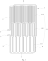
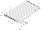
- 1 cooling pipe set 11 cooling pipe; 111 tree-like beginning; 112 tree-like intermediate; 113 tree-like end; 2 pipe outlet; 3 pipe inlet; 4 outlet main; 5 inlet main; 6 second surrounding pipe; 7 first surrounding pipe; 8 third surrounding pipe; 9 cooling plate body; 10 lateral liquid cooling plate; 101 liquid outlet; 102 liquid inlet; 103 liquid outlet pipe; 104 liquid inlet pipe; 20 converging pipe; 30 diverting pipe.
- cooling pipes are typically coiled curved pipes or serpentine pipes. The longer the coolant in the cooling pipe flows and exchanges heat as it enters the cooling pipe, the higher the temperature of the coolant becomes, and therefore the heat exchange effect is not optimal for the heat generating devices positioned in the rear half of the cooling pipe.
- a cooling pipe structure including a cooling pipe set 1, a pipe inlet 3, and a pipe outlet 2, in which the cooling pipe set 1 includes at least one cooling pipe 11, and a flow direction of liquid in the cooling pipe 11 is defined as a first direction. It is to be understood that, the first direction is the predominant flow direction in the cooling pipe 11. A partial turning structure may be presented in the cooling pipe 11, however, the predominant flow direction remains unchanged.
- the first direction is a length direction of the cooling pipe set
- the cooling pipes 11 are arranged in a tree-like structure from a side to an opposite side along the first direction
- the tree-like structure contains at least two levels
- the tree-like structure includes a tree-like beginning 111 and a tree-like end 113 when the tree-like structure contains two levels
- the tree-like structure includes a tree-like beginning 111,a tree-like intermediate 112, and a tree-like end 113 when the tree-like structure contains more than three levels
- a side of the tree-like structure is the tree-like beginning 111, an opposite side thereof is a tree-like end 113
- the tree-like intermediate 112 is positioned between the tree-like beginning 111 and the tree-like end 113.
- the pipe inlet 3 is in communication with a side of the tree-like beginning 111 of the cooling pipe 11 in the cooling pipe set 1, and the pipe outlet 2 is in communication with a side of the tree-like end 113 of the cooling pipe 11 in the cooling pipe set 1.
- the coolant temperature inside the cooling pipes 11 increases with the increase of the length of the pipes, and the number of cooling pipes 11 is increased level by level by designing the cooling pipe set 1 with a tree-like structure distribution of the cooling pipes 11.
- the number of levels of the tree-like structure is increased according to the area of heat exchange required to ensure that the heat exchange in the rear half of the cooling pipe 11 is more intensive, thereby gradually increasing the area in contact with the heat generating members, effectively addressing the gradual temperature rise in the coolant in the cooling pipe 11, increasing the area of the heat exchange, reducing the temperature difference between the cells, controlling the temperature of the heat generating members in a reasonable range, achieving the evenness of heat exchange, and conducive to increasing the service life of the heat generating members.
- the cooling pipe set 1 includes only one cooling pipe 11, the cooling pipe 11 is connected to the pipe inlet 3, respective sides of the tree-like ends 113 of the cooling pipes 11 are converged to one pipe and connected to the pipe outlet 2, the coolant passed through the pipe inlet 3 first flows through the tree-like beginning 111 of the cooling pipe 11, then flows through the tree-like end 113 of the cooling pipe 11, and finally flows out of the pipe outlet 2 to achieve the heat exchange effect of the coolant.
- the cooling pipe set 1 when the cooling pipe set 1 includes two or more cooling pipes 11, all cooling pipes 11 are positioned on a same horizontal plane, and all cooling pipes 11 in the cooling pipe set 1 are kept horizontal, so that the cooling pipe set 1 forms a cooling plane, tree-like beginnings 111 of all cooling pipes 11 are connected to an inlet main 5, the inlet main 5 is in communication with the pipe inlet 3, tree-like ends 113 of all cooling pipes 11 are connected to an outlet main 4, and the outlet main 4 is in communication with the pipe outlet 2.
- the provision of the inlet main 5 and the outlet main 4 enables each cooling pipe 11 to be relatively fixed between the inlet main 5 and the outlet main 4 to form a plane.
- the coolant passed through the pipe inlet 3 first flows into the inlet main 5, then disperses to the tree-like beginnings 111 of each cooling pipe 11, then flows through the tree-like ends 113 of each cooling pipe 11, and finally passes into the outlet main 4 and out of the pipe outlet 2 to achieve the heat exchange effect of the coolant.
- the cooling pipe set 1 when the cooling pipe set 1 includes two or more cooling pipes 11, all cooling pipes are positioned on different horizontal plane, which allows the cooling pipe set 1 to dissipate heat on multiple surfaces of the heat generating object, so that each cooling pipe 11 in the cooling pipe set 1 may be changed adaptively according to the shape of the surface of the heat generating object.
- the inlet main 5 may be provided along a circumference of a circle on a side of the cylinder
- the outlet main 4 may be provided along a circumference of a circle on an opposite side of the cylinder.
- All cooling pipes 11 are arranged in a spaced apart arrangement between the inlet main 5 and the outlet main 4, all cooling pipes 11 in the cooling pipe set 1 are kept horizontal, and the cooling pipes 11 are connected to the inlet main 5 and the outlet main 4 vertically, or in an angle so that all cooling pipes 11 are coiled along the side surface of the cylinder to achieve the heat exchange effect.
- the inlet main 5 may be provided along a periphery of a polygonal plane on a side of the prism
- the outlet main 4 may be provided along a periphery of a polygonal plane on an opposite side of the prism.
- All cooling pipes 11 are arranged in a spaced apart arrangement between the inlet main 5 and the outlet main 4, and all cooling pipes 11 in the cooling pipe set 1 are kept horizontal, so as to cover at least one lateral surface of the prism to achieve the heat exchange effect.
- the heat generating object is a truncated conical prism or a truncated cone
- the inlet main 5 and the outlet main 4 are still provided on peripheries of both end surfaces.
- All cooling pipes 11 are arranged in a spaced apart arrangement between the inlet main 5 and the outlet main 4, and all cooling pipes are not horizontal in this case, so as to cover at least a part of lateral surfaces of the truncated conical prism or truncated cone to achieve the heat exchange effect.
- the number of levels of the tree-like structure in the cooling pipes 11 is preferably two, three or four, and the number of pipes in each level of the tree-like structure is doubled that in the prior level of the tree-like structure. Therefore, a distance between two tree-like beginnings111 of the cooling pipes 11 needs to be greater than or equal to a width range of the tree-like ends 113, so as to ensure a smooth arrangement between the cooling pipes 11. Therefore, the tree-like structure is a binary tree-like structure, and branches of each level of tree-like structure are parallel to each other, so as to prevent from diverting too much flow, which may lead to the cooling pipes 11 positioned on a side of the tree-like beginning 111 being spaced too far apart and result in a poor heat exchange effect.
- a third surrounding pipe 8 is provided between the outlet main 4 and the inlet main 5, the third surrounding pipe 8 is positioned at ends of the outlet main 4 and the inlet main 5, and positioned at edges of the cooling pipe set 1, so as to provide supplementary heat exchange to areas where the tree-like beginning 111 is not able to exchange heat, which increases an overall heat exchange area of the cooling pipe set 1.
- the pipe inlet 3 and pipe outlet 2 typically need to be designed in a centralized manner, so that the occupation of overall area of the cooling pipe set 1 may be decreased. Therefore, a side of the inlet main 5 is further provided with a first surrounding pipe 7, a side of the outlet main 4 is further provided with a second surrounding pipe 6, the third surrounding pipe 8 is provided between an opposite side of the inlet main 5 and an opposite side of the outlet main 4, the first surrounding pipe 7 and the second surrounding pipe 6 are provided around a lateral edge of the cooling pipe set 1, an end of the first surrounding pipe 7 is in communication with the pipe inlet 3, and an end of the second surrounding pipe 6 is in communication with the pipe outlet 2, so that the pipe inlet 3 and the pipe outlet 2 may be designed in a centralized manner, and the occupation of overall area of the cooling pipe set 1 may be decreased, which leads to an increase of the area of heat exchange.
- a liquid cooling plate including a liquid cooling plate body 9 and any one of the cooling pipe structure mentioned above, in which the cooling pipe set 1 is abutted against or embedded into at least one side surface of the liquid cooling plate body 9, so that the heat exchange area of the liquid cooling plate from one side to the other side is gradually increased to address a gradual increase in the temperature of the coolant in the cooling pipe 11 on the cooling plate, which is conducive to balancing the temperature of the liquid cooling plate from one side to the other side in the horizontal direction.
- the liquid cooling plate body 9 may be a coplanar flat plate structure for exchanging heat for a single-sided of the heat generating source, or a non-coplanar bent plate structure for exchanging heat for at least two sides of the heat generating source, or a plurality of liquid cooling plates may be assembled to form a cooling housing for exchanging heat for the heat generating source in a comprehensive manner.
- the liquid cooling plate body 9 is a coplanar flat plate, the set of cells and the liquid cooling plate body 9 are provided in the cell housing, and the liquid cooling plate body 9 is positioned on a top or bottom of the set of cells, which is conducive to the heat exchange on the top or bottom of the set of cells, ensuring an even heat exchange of the set of cells.
- a flow direction of the cooling pipe 11 on the liquid cooling plate body 9 is identical to a length direction of the cell housing, which is conducive to the arrangement of the tree-like structure to achieve an even heat exchange. It should be noted that, in other implementations, the liquid cooling plate body 9 may further be assembled on six sides of the set of cells to achieve full heat exchange.
- the set of cells includes a plurality of rows of cells provided in a linear arrangement, both sides of each row of cells are provided with lateral liquid cooling plates 10, the lateral liquid cooling plates 10 are abutted against side walls of the cells, and an interior of the lateral liquid cooling plates 10 is in communication with an interior of the liquid cooling plate body 9.
- Each lateral liquid cooling plate 10 includes a liquid inlet 102 and a liquid outlet 101, the liquid inlets 102 of the lateral liquid cooling plates 10 are connected in series to form a liquid inlet pipe 104, and the liquid outlets 101 of the lateral liquid cooling plates 10 are connected in series to form a liquid outlet pipe 103.
- the coolant When filling coolant, the coolant is sent to each liquid inlet pipe 104 and the pipe inlet 3 of the liquid cooling plate body 9 through the diverting pipe 30, and then flows out through each liquid outlet pipe 103 and the pipe outlet 2 of the liquid cooling plate body 9 after flowing through the lateral liquid cooling plate 10 and the liquid cooling plate body 9, respectively, and is finally aggregated and discharged through the converging pipe 20.
- the combination of the lateral liquid cooling plate 10 and the liquid cooling plate body 9 may achieve three-side cooling on a top or bottom surface of the cells as well as on both sides of the cells, greatly increasing the heat exchange area between the cells and the coolant, and improving the charging safety of the cells when charging at a high rate.
- the cells are cylindrical, and the lateral liquid cooling plate 10 are designed as a serpentine liquid cooling plate, which is conducive to adhering to the side wall surface of the cells and improving the heat exchange area.
- the structure of the lateral liquid cooling plate 10 varies with the shapes of the cells.
- Each level of the tree-like structure in the cooling pipe 11 inside the liquid cooling plate body 9 covers 6-9 cells, the number of cells being cooled in each level is not too many, which avoids severe uneven cooling issues that may result from the decline in heat exchange efficiency.
- the tree-like structure contains three levels.
- the cooling pipes 11 are in contact with and exchange heat with an aluminum plate above the cells.
- the stamped liquid cooling plate body 9 at the top of the cells is in direct contact with the welded aluminum plate above the cells, and when the aluminum plate generates excessive heat during high rate charging, the liquid cooling plate body 9 at the top exchanges heat with the aluminum plate, while the aluminum plate is welded to the poles of the cells, thereby cooling the cells.
- the present application provides a cooling pipe structure, a liquid cooling plate and a battery system with the following technical effects:
Landscapes
- Chemical & Material Sciences (AREA)
- Chemical Kinetics & Catalysis (AREA)
- Electrochemistry (AREA)
- General Chemical & Material Sciences (AREA)
- Engineering & Computer Science (AREA)
- Manufacturing & Machinery (AREA)
- Secondary Cells (AREA)
- Fuel Cell (AREA)
Applications Claiming Priority (3)
| Application Number | Priority Date | Filing Date | Title |
|---|---|---|---|
| CN202321668701.3U CN219998342U (zh) | 2023-06-28 | 2023-06-28 | 一种冷却流道结构、液冷板及电池系统 |
| CN202310777273.6A CN116780024A (zh) | 2023-06-28 | 2023-06-28 | 一种冷却流道结构、液冷板及电池系统 |
| PCT/CN2024/100905 WO2025002041A1 (zh) | 2023-06-28 | 2024-06-24 | 一种冷却流道结构、液冷板及电池系统 |
Publications (2)
| Publication Number | Publication Date |
|---|---|
| EP4510309A1 true EP4510309A1 (de) | 2025-02-19 |
| EP4510309A4 EP4510309A4 (de) | 2026-03-25 |
Family
ID=92931624
Family Applications (1)
| Application Number | Title | Priority Date | Filing Date |
|---|---|---|---|
| EP24772546.8A Pending EP4510309A4 (de) | 2023-06-28 | 2024-06-24 | Kühlströmungskanalstruktur, flüssigkeitskühlplatte und batteriesystem |
Country Status (5)
| Country | Link |
|---|---|
| US (1) | US20250096351A1 (de) |
| EP (1) | EP4510309A4 (de) |
| JP (1) | JP7853437B2 (de) |
| KR (1) | KR20240139606A (de) |
| FI (1) | FIU20244062U1 (de) |
Family Cites Families (8)
| Publication number | Priority date | Publication date | Assignee | Title |
|---|---|---|---|---|
| US7851080B2 (en) * | 2008-04-09 | 2010-12-14 | Gm Global Technology Operations, Inc. | Battery cooling plate design with discrete channels |
| CN204497218U (zh) * | 2015-03-20 | 2015-07-22 | 中兴通讯股份有限公司 | 一种液冷冷板 |
| CN107611524B (zh) * | 2017-08-30 | 2024-03-26 | 江苏福瑞士电池科技有限公司 | 动力电池温度调节用液体换热板 |
| CN109742420A (zh) * | 2018-12-29 | 2019-05-10 | 上海齐耀动力技术有限公司 | 一种树状流场结构的燃料电池双极板 |
| CN109830704B (zh) * | 2019-02-01 | 2020-12-25 | 广东电科院能源技术有限责任公司 | 基于树状流道结构的氢燃料电池双极板 |
| CN214753909U (zh) * | 2021-04-09 | 2021-11-16 | 海汇新能源汽车有限公司 | 用于动力电池冷却的冷板结构 |
| CN217788556U (zh) * | 2022-01-28 | 2022-11-11 | 湖北亿纬动力有限公司 | 一种液冷系统及电池包 |
| CN218005016U (zh) * | 2022-06-30 | 2022-12-09 | 湖北亿纬动力有限公司 | 一种直冷板组件及电池系统 |
-
2024
- 2024-06-24 JP JP2024555232A patent/JP7853437B2/ja active Active
- 2024-06-24 FI FIU20244062U patent/FIU20244062U1/fi active
- 2024-06-24 KR KR1020247029758A patent/KR20240139606A/ko active Pending
- 2024-06-24 EP EP24772546.8A patent/EP4510309A4/de active Pending
- 2024-12-02 US US18/966,095 patent/US20250096351A1/en active Pending
Also Published As
| Publication number | Publication date |
|---|---|
| JP7853437B2 (ja) | 2026-04-28 |
| JP2025524268A (ja) | 2025-07-28 |
| KR20240139606A (ko) | 2024-09-23 |
| EP4510309A4 (de) | 2026-03-25 |
| FIU20244062U1 (fi) | 2024-10-16 |
| US20250096351A1 (en) | 2025-03-20 |
Similar Documents
| Publication | Publication Date | Title |
|---|---|---|
| CN114267901A (zh) | 一种电池模组及电池包 | |
| CN115498327B (zh) | 一种冷却装置及电池模组 | |
| CN216288649U (zh) | 一种液冷储能电池包 | |
| CN216958222U (zh) | 一种电池包的浸没式内循环液冷结构 | |
| CN216928712U (zh) | 一种电池箱的外循环液冷结构 | |
| CN110994072A (zh) | 一种用于锂电池的并联式多通道液冷结构及锂电池 | |
| CN214378603U (zh) | 一种用于电动汽车锂离子电池的热管理装置 | |
| CN108075081A (zh) | 电池组、电池包及具有该电池包的车辆 | |
| CN116780024A (zh) | 一种冷却流道结构、液冷板及电池系统 | |
| CN114050354A (zh) | 一种储能集装箱 | |
| CN215220832U (zh) | 一种储能集装箱 | |
| CN207800826U (zh) | 一种分流式散热的电池包 | |
| CN221486624U (zh) | 电池包和具有其的用电系统 | |
| CN219998342U (zh) | 一种冷却流道结构、液冷板及电池系统 | |
| EP4535510A1 (de) | Batteriepack und fahrzeug damit | |
| KR20250000072U (ko) | 대면적 온도 균일화 액체냉각판 | |
| CN218101456U (zh) | 换热装置、动力电池包和车辆 | |
| EP4510309A1 (de) | Kühlströmungskanalstruktur, flüssigkeitskühlplatte und batteriesystem | |
| CN119812573A (zh) | 一种用于液冷电池包的液冷系统 | |
| CN117673565B (zh) | 电池液冷结构、电池模组及电池包 | |
| CN221530043U (zh) | 一种电池冷却装置及系统 | |
| CN219286512U (zh) | 电池包 | |
| CN220796893U (zh) | 一种电池模组和电池包 | |
| EP4535509A1 (de) | Batteriepack und fahrzeug damit | |
| CN220121937U (zh) | 域控电池包及车辆 |
Legal Events
| Date | Code | Title | Description |
|---|---|---|---|
| STAA | Information on the status of an ep patent application or granted ep patent |
Free format text: STATUS: UNKNOWN |
|
| STAA | Information on the status of an ep patent application or granted ep patent |
Free format text: STATUS: THE INTERNATIONAL PUBLICATION HAS BEEN MADE |
|
| PUAI | Public reference made under article 153(3) epc to a published international application that has entered the european phase |
Free format text: ORIGINAL CODE: 0009012 |
|
| STAA | Information on the status of an ep patent application or granted ep patent |
Free format text: STATUS: REQUEST FOR EXAMINATION WAS MADE |
|
| 17P | Request for examination filed |
Effective date: 20240925 |
|
| AK | Designated contracting states |
Kind code of ref document: A1 Designated state(s): AL AT BE BG CH CY CZ DE DK EE ES FI FR GB GR HR HU IE IS IT LI LT LU LV MC ME MK MT NL NO PL PT RO RS SE SI SK SM TR |
|
| A4 | Supplementary search report drawn up and despatched |
Effective date: 20260220 |
|
| RIC1 | Information provided on ipc code assigned before grant |
Ipc: H01M 10/613 20140101AFI20260216BHEP Ipc: H01M 10/625 20140101ALI20260216BHEP Ipc: H01M 10/643 20140101ALI20260216BHEP |