EP4510364A1 - Ensemble électrode, cellule de batterie, batterie, dispositif électrique et appareil de mise en forme de languette - Google Patents
Ensemble électrode, cellule de batterie, batterie, dispositif électrique et appareil de mise en forme de languette Download PDFInfo
- Publication number
- EP4510364A1 EP4510364A1 EP22957671.5A EP22957671A EP4510364A1 EP 4510364 A1 EP4510364 A1 EP 4510364A1 EP 22957671 A EP22957671 A EP 22957671A EP 4510364 A1 EP4510364 A1 EP 4510364A1
- Authority
- EP
- European Patent Office
- Prior art keywords
- tab
- electrode plate
- tabs
- electrode assembly
- current collector
- Prior art date
- Legal status (The legal status is an assumption and is not a legal conclusion. Google has not performed a legal analysis and makes no representation as to the accuracy of the status listed.)
- Pending
Links
Images


Classifications
-
- H—ELECTRICITY
- H01—ELECTRIC ELEMENTS
- H01M—PROCESSES OR MEANS, e.g. BATTERIES, FOR THE DIRECT CONVERSION OF CHEMICAL ENERGY INTO ELECTRICAL ENERGY
- H01M50/00—Constructional details or processes of manufacture of the non-active parts of electrochemical cells other than fuel cells, e.g. hybrid cells
- H01M50/50—Current conducting connections for cells or batteries
- H01M50/531—Electrode connections inside a battery casing
- H01M50/538—Connection of several leads or tabs of wound or folded electrode stacks
-
- H—ELECTRICITY
- H01—ELECTRIC ELEMENTS
- H01M—PROCESSES OR MEANS, e.g. BATTERIES, FOR THE DIRECT CONVERSION OF CHEMICAL ENERGY INTO ELECTRICAL ENERGY
- H01M10/00—Secondary cells; Manufacture thereof
- H01M10/04—Construction or manufacture in general
- H01M10/0404—Machines for assembling batteries
- H01M10/0409—Machines for assembling batteries for cells with wound electrodes
-
- H—ELECTRICITY
- H01—ELECTRIC ELEMENTS
- H01M—PROCESSES OR MEANS, e.g. BATTERIES, FOR THE DIRECT CONVERSION OF CHEMICAL ENERGY INTO ELECTRICAL ENERGY
- H01M10/00—Secondary cells; Manufacture thereof
- H01M10/04—Construction or manufacture in general
- H01M10/0431—Cells with wound or folded electrodes
-
- H—ELECTRICITY
- H01—ELECTRIC ELEMENTS
- H01M—PROCESSES OR MEANS, e.g. BATTERIES, FOR THE DIRECT CONVERSION OF CHEMICAL ENERGY INTO ELECTRICAL ENERGY
- H01M10/00—Secondary cells; Manufacture thereof
- H01M10/05—Accumulators with non-aqueous electrolyte
- H01M10/052—Li-accumulators
-
- H—ELECTRICITY
- H01—ELECTRIC ELEMENTS
- H01M—PROCESSES OR MEANS, e.g. BATTERIES, FOR THE DIRECT CONVERSION OF CHEMICAL ENERGY INTO ELECTRICAL ENERGY
- H01M10/00—Secondary cells; Manufacture thereof
- H01M10/05—Accumulators with non-aqueous electrolyte
- H01M10/054—Accumulators with insertion or intercalation of metals other than lithium, e.g. with magnesium or aluminium
-
- H—ELECTRICITY
- H01—ELECTRIC ELEMENTS
- H01M—PROCESSES OR MEANS, e.g. BATTERIES, FOR THE DIRECT CONVERSION OF CHEMICAL ENERGY INTO ELECTRICAL ENERGY
- H01M10/00—Secondary cells; Manufacture thereof
- H01M10/05—Accumulators with non-aqueous electrolyte
- H01M10/058—Construction or manufacture
- H01M10/0587—Construction or manufacture of accumulators having only wound construction elements, i.e. wound positive electrodes, wound negative electrodes and wound separators
-
- H—ELECTRICITY
- H01—ELECTRIC ELEMENTS
- H01M—PROCESSES OR MEANS, e.g. BATTERIES, FOR THE DIRECT CONVERSION OF CHEMICAL ENERGY INTO ELECTRICAL ENERGY
- H01M50/00—Constructional details or processes of manufacture of the non-active parts of electrochemical cells other than fuel cells, e.g. hybrid cells
- H01M50/50—Current conducting connections for cells or batteries
- H01M50/531—Electrode connections inside a battery casing
- H01M50/533—Electrode connections inside a battery casing characterised by the shape of the leads or tabs
-
- H—ELECTRICITY
- H01—ELECTRIC ELEMENTS
- H01M—PROCESSES OR MEANS, e.g. BATTERIES, FOR THE DIRECT CONVERSION OF CHEMICAL ENERGY INTO ELECTRICAL ENERGY
- H01M2220/00—Batteries for particular applications
- H01M2220/20—Batteries in motive systems, e.g. vehicle, ship, plane
-
- Y—GENERAL TAGGING OF NEW TECHNOLOGICAL DEVELOPMENTS; GENERAL TAGGING OF CROSS-SECTIONAL TECHNOLOGIES SPANNING OVER SEVERAL SECTIONS OF THE IPC; TECHNICAL SUBJECTS COVERED BY FORMER USPC CROSS-REFERENCE ART COLLECTIONS [XRACs] AND DIGESTS
- Y02—TECHNOLOGIES OR APPLICATIONS FOR MITIGATION OR ADAPTATION AGAINST CLIMATE CHANGE
- Y02E—REDUCTION OF GREENHOUSE GAS [GHG] EMISSIONS, RELATED TO ENERGY GENERATION, TRANSMISSION OR DISTRIBUTION
- Y02E60/00—Enabling technologies; Technologies with a potential or indirect contribution to GHG emissions mitigation
- Y02E60/10—Energy storage using batteries
-
- Y—GENERAL TAGGING OF NEW TECHNOLOGICAL DEVELOPMENTS; GENERAL TAGGING OF CROSS-SECTIONAL TECHNOLOGIES SPANNING OVER SEVERAL SECTIONS OF THE IPC; TECHNICAL SUBJECTS COVERED BY FORMER USPC CROSS-REFERENCE ART COLLECTIONS [XRACs] AND DIGESTS
- Y02—TECHNOLOGIES OR APPLICATIONS FOR MITIGATION OR ADAPTATION AGAINST CLIMATE CHANGE
- Y02P—CLIMATE CHANGE MITIGATION TECHNOLOGIES IN THE PRODUCTION OR PROCESSING OF GOODS
- Y02P70/00—Climate change mitigation technologies in the production process for final industrial or consumer products
- Y02P70/50—Manufacturing or production processes characterised by the final manufactured product
Definitions
- This application relates to the technical field of batteries, and in particular, to an electrode assembly, a battery cell, a battery, an electrical device, and a tab shaping apparatus.
- a rechargeable battery cell also known as a secondary battery cell, is a battery cell that is reusable after the active material is activated by charging the battery cell that is discharged.
- Rechargeable battery cells are widely used in electronic devices such as a mobile phone, a notebook computer, an electric power cart, an electric vehicle, an electric airplane, an electric ship, an electric toy car, an electric toy ship, an electric toy airplane, and a power tool.
- an electrode assembly is prone to incur some battery performance problems or safety problems related to a tab during formation of the electrode assembly.
- This application aims to solve at least one of technical problems of an electrode assembly in the prior art.
- an objective of this application is to disclose an electrode assembly, a battery cell, a battery, an electrical device, and a tab shaping apparatus.
- An embodiment in a first aspect of this application provides an electrode assembly, including a first electrode plate and a second electrode plate that are of opposite polarities, and including a separator disposed between the first electrode plate and the second electrode plate.
- the first electrode plate, the separator, and the second electrode plate are wound along a winding direction to form a jelly-roll structure.
- At least one of the first electrode plate or the second electrode plate includes: a current collector; an active material layer, disposed at least on a surface of the current collector on a side near the separator; and a tab portion, connected to one lateral edge of the current collector, where the lateral edge extends along the winding direction.
- the tab portion includes a continuous region near the active material layer and a spacing region away from the active material layer.
- the spacing region includes a plurality of tabs spaced apart along the winding direction.
- the tab portion includes a continuous region and a spacing region.
- the spacing region includes a plurality of tabs spaced apart along the winding direction.
- the tabs may be formed by a process such as die-cutting.
- a height of the tab portion before bending of the tabs is h0, and a height of each tab before bending of the tab is h1, and h0 and h1 satisfy: 0.25 ⁇ h1/h0 ⁇ 1.
- the height relationship between the tab portion and the tab disclosed in this embodiment ensures that the thickness of a dense layer formed after the flattening of the tab meets welding conditions, and also alleviates the problem of detachment of the active material coating layer caused by the slitting of the tab as well as the problem of burning the separator during welding of the tab portion.
- this application can more satisfactorily achieve the desired thickness of the dense layer, alleviate the problem of detachment of the active material coating layer, and avoid the problem of burning the separator during welding, and can more sufficiently satisfy the conditions of welding and tab slitting, and improve the yield rate of prepared electrode assemblies.
- each tab is bent and pressed flat against the current collector.
- a maximum distance from a bend line to a top of the tab is h2.
- a height of the tab before bending of the tab is h1, and h1 and h2 satisfy: 0.3 ⁇ h2/h1 ⁇ 1.
- the dimensional relationship between the tab and the bent part disclosed in this embodiment ensures that the thickness of the dense layer formed after the flattening of the tab meets the welding conditions, and also improves the infiltration performance of an electrolyte solution, and improves the cycle performance and power performance of the electrolyte solution.
- the jelly-roll structure is a cylindrical jelly-roll structure.
- a diameter of a center roll of the j elly-roll structure is d
- a width of the tab is 1, and l and d satisfy: 0.7 ⁇ 1/d ⁇ 2.
- the relationship between the width of the tab and the diameter of the innermost coil of the jelly-roll structure disclosed in this embodiment can ensure that the denseness of the dense layer formed after the flattening of the tab meets the welding conditions, and can also avoid a decline in the yield rate caused by the folding, tearing, and other problems of the tabs occurring during the winding of a bare cell.
- a maximum spacing between adjacent tabs in the tab portion is g
- a width of each tab is l
- l and g satisfy: g/1 ⁇ 0.2.
- the relationship between the tab width and the tab spacing disclosed in this embodiment ensures that the thickness of the dense layer formed after the flattening of the tab meets the welding conditions, and improves the welding quality.
- a height of the tab portion before bending of the tabs is h0, satisfying: 3 mm ⁇ h0 ⁇ 8 mm; and/or, a height of each tab before bending of the tab is h1, satisfying: 1 mm ⁇ h1 ⁇ 8 mm; and/or at least a part of the tab is bent and pressed flat against the current collector, a maximum distance from a bend line to a top of the tab is h2, and h2 satisfies: 1 mm ⁇ h 2 ⁇ 8 mm .
- the design of the dimensions of the tab portion, the tabs, and the bent part disclosed in this embodiment makes the flattened tabs overlap each other to form a denser dense layer, and significantly reduces the probability of being punctured by laser welding, thereby improving the welding quality, and also avoiding the problems such as detachment of the active material layer and a lower infiltration effect of the electrolyte solution.
- the height h0 satisfies: 4 mm ⁇ h0 ⁇ 7 mm
- the height h1 satisfies: 2 mm ⁇ h1 ⁇ 7 mm
- the distance h2 satisfies: 2 mm ⁇ h2 ⁇ 7 mm.
- the design of the dimensions of the tab portion, the tabs, and the bent part disclosed in this embodiment makes the flattened tabs overlap each other to form a denser dense layer, and significantly reduces the probability of being punctured by laser welding, thereby further improving the welding quality, and more effectively avoiding the problems such as detachment of the active material layer and a lower infiltration effect of the electrolyte solution.
- the tabs are inclined to one lateral edge of the current collector, and the lateral edge extends along the winding direction.
- the tabs of the electrode plate extend at an inclination to the lateral edge of the current collector, thereby further reducing the strength of the tabs in the spacing region, making it easier to press the tabs flat, improving the denseness and thickness of the dense layer formed after the tabs are pressed flat, and improving the yield rate of welding.
- an inclination direction of the tabs is opposite to the winding direction. With the inclination direction of the tabs being opposite to the winding direction of the electrode plate, the tabs is less prone to be folded and broken during winding of the electrode plate, thereby improving the yield rate of the j elly-roll structure.
- each tab is bent and pressed flat against the current collector.
- the bent part of the tab is bent by an extrusion head that rotates and squeezes.
- An inclination direction of the tabs is identical to a rotation direction of the extrusion head. With the inclination direction of the tab being identical to the rotation direction of the extrusion head, this application avoids damage to the tabs during the flattening, especially the tabs at the outer coil and the ending of the jelly-roll structure, and improves the yield rate of the jelly-roll structure.
- an inclination angle ⁇ of the tabs satisfies: 45° ⁇ ⁇ ⁇ 90°.
- the inclination angle ⁇ of the tabs disclosed in this embodiment can effectively reduce the bending strength of the tabs, make it easier to press the tabs flat, and effectively avoid the problems of folding and breaking the tabs during the winding and/or flattening.
- a bevel edge formed by cutting a corner is disposed on an ending side of a tab located at an ending of the j elly-roll structure.
- the tab at the ending of the electrode plate is die-cut to cut away the corner at the ending end of the tab, thereby alleviating such problems.
- At least a part of the bevel edge is arc-shaped.
- An embodiment in a second aspect of this application provides a battery cell.
- the battery cell includes the electrode assembly according to the above embodiment.
- the tab is bent and pressed flat against the current collector.
- a maximum distance from a bend line to a top of the tab is h2.
- the jelly-roll structure is a cylindrical jelly-roll structure.
- the battery cell further includes: a current collecting plate, located on one side of the cylindrical jelly-roll structure, the side being connected to the tab portion.
- the current collecting plate is fixedly connected to the bent part of the tab by welding.
- a thickness of the current collecting plate is t1, and t1 and h2 satisfy: 0.05 ⁇ t1/h2 ⁇ 0.2.
- the relationship between the height of the bent part of the tab and the thickness of the current collecting plate disclosed in this embodiment ensures that the thickness of the dense layer formed after the flattening of the tab meets the welding conditions, and also increases the capacity of the battery.
- An embodiment in a third aspect of this application provides a battery.
- the battery includes the battery cell according to the above embodiment.
- An embodiment in a fourth aspect of this application provides an electrical device.
- the electrical device includes the battery disclosed in the preceding embodiment.
- the battery is configured to provide electrical energy.
- An embodiment in a fifth aspect of this application provides a tab shaping apparatus, including an extrusion head.
- the extrusion head is configured to smooth the tabs in the electrode assembly according to any one of the above embodiments so that at least a part of each tab is bent and pressed flat against the current collector.
- the tabs are inclined to one lateral edge of the current collector, and the lateral edge extends along the winding direction.
- a rotation direction of the extrusion head is configured to be identical to an inclination direction of the tabs.
- this application avoids damage to the tabs during the flattening, especially the tabs at the outer coil and the ending of the jelly-roll structure, and improves the yield rate of the j elly-roll structure.
- the term "and/or” merely indicates a relationship between related items, and represents three possible relationships.
- “A and/or B” may represent the following three circumstances: A alone, both A and B, and B alone.
- the character “/” herein generally indicates an "or” relationship between the item preceding the character and the item following the character.
- a plurality of means two or more (including two).
- a plurality of groups means two or more groups (including two groups), and "a plurality of pieces” means two or more pieces (including two pieces).
- a direction or a positional relationship indicated by the terms such as “center”, “longitudinal”, “transverse”, “length”, “width”, “thickness”, “up”, “down”, “before”, “after”, “left”, “right”, “vertical”, “horizontal”, “top”, “bottom”, “in”, “out”, “clockwise”, “counterclockwise”, “axial”, “radial”, and “circumferential” is a direction or positional relationship based on the illustration in the drawings, and is merely intended for ease or brevity of description of embodiments of this application, but not intended to indicate or imply that the indicated device or component is necessarily located in the specified direction or constructed or operated in the specified direction. Therefore, such terms are not to be understood as a limitation on embodiments of this application.
- Power batteries are not only used in energy storage power systems such as hydro, thermal, wind, and solar power stations, but also widely used in electric means of transport such as electric bicycles, electric motorcycles, and electric vehicles, and used in many other fields such as military equipment and aerospace.
- the market demand for power batteries keeps soaring with the increase of the application fields of the power batteries.
- an electrode assembly in a cylindrical battery cell includes a long tab extending beyond an end portion of a jelly-roll structure.
- the long tab extends continuously along a winding direction of the electrode plate.
- the long tab Before the long tab is welded to a current collecting plate, the long tab needs to be bent and smoothed to form a structure in which the tabs overlap each other layer by layer from the outside to the inside.
- the long tab After research by the inventor, it is found that the long tab exhibits a specified curvature along with the winding of the electrode plate.
- the curved long tab is prone to be wrinkled when being pressed flat, and therefore, is prone to be broken and damaged.
- the long tab wound into a ring shape is of high bending strength.
- the deformation generated when the tab is squeezed and collapsed can hardly be ensured to be continuous and uniform. Therefore, the stacked layers of the flattened tabs are not uniform enough, and the denseness of the tabs is low.
- the tabs are prone to be punctured when being welded to the current collecting plate, posing a very grim challenge to the manufacturing equipment and process.
- some embodiments of the present disclosure provide an electrode assembly, a battery cell, a battery, an electrical device, and a tab shaping apparatus to improve safety performance of the battery.
- the electrode assembly according to embodiments of the present disclosure is applicable to various battery cells.
- the battery cell may be a lithium-ion secondary battery, a lithium-ion primary battery, a lithium-sulfur battery, a sodium-lithium-ion battery, a sodium-ion battery, a magnesium-ion battery, or the like.
- the type of the battery cell is not limited herein.
- the battery cell may be in various shapes such as cylindrical, flat, cuboidal or other shapes. The shape of the battery cell is not limited herein. In terms of the packaging form, the battery cell is typically classed into: cylindrical battery cell, prismatic battery cell, and pouch-type battery cell. The type of the battery cell is not limited herein.
- the battery cell according to embodiments of the present disclosure is applicable to various batteries.
- a battery can supply power to electrical devices such as a vehicle, for example, provide a power supply for maneuvering the vehicle or a power supply for driving the vehicle.
- the battery may include a box and a battery module.
- the box is configured to provide an accommodation space for the battery module.
- the battery module is mounted in the box.
- the box may be made of a metal material.
- the battery module may include a plurality of battery cells connected in series, parallel, or series-and-parallel pattern.
- the battery cell is a minimum unit of a battery.
- the battery cell includes an electrode assembly in which electrochemical reactions occur.
- the battery according to embodiments of the present disclosure is applicable to various electrical devices powered by a battery.
- the electrical device may be a mobile phone, a portable device, a notebook computer, an electric power cart, an electric vehicle, a ship, a spacecraft, an electric toy, an electric tool, or the like.
- the spacecraft includes an airplane, a rocket, a space shuttle, a spaceship, and the like.
- the electric toy includes a fixed or mobile electric toy, such as a game console, an electric car toy, an electric ship toy, an electric airplane toy, and the like.
- the electric tool includes an electric tool for metal cutting, an electric grinding tool, an electric assembly tool, an electric tool for railways, such as an electric drill, an electric grinder, an electric wrench, an electric screwdriver, an electric hammer, an electric impact drill, a concrete vibrator, and an electric planer.
- the electrical device is not particularly limited herein.
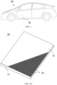
- FIG. 1 is a schematic structural diagram of an electrical device according to some embodiments of the present disclosure.
- a vehicle is used as an example of the electrical device.
- a battery 30 is disposed inside the vehicle 40.
- the battery 30 may be disposed at the bottom, front, or rear of the vehicle 40.
- the battery 30 is configured to supply power to the vehicle 40.
- the battery 30 serves as an operating power supply of the vehicle 40.
- the vehicle 40 may further include a controller and a motor.
- the controller is configured to control the battery 30 to supply power to the motor, for example, to meet electrical energy requirements in starting, navigating, or running the vehicle 40.
- the battery 30 serves not only as an operating power supply of the vehicle 40, but may also serve as a driving power supply of the vehicle 40 to provide driving power for the vehicle 40 in place of or partly in place of fuel oil or natural gas.
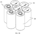
- FIG. 2A is a schematic structural diagram of a battery according to some embodiments of the present disclosure.
- FIG. 2B is a schematic structural diagram of a plurality of battery cells electrically connected in a battery according to some embodiments of the present disclosure.
- the battery 30 includes a box and one or more battery cells 20 disposed in the box.
- the box includes a first box 31 and a second box 32.
- the first box 31 and the second box 32 fit each other.
- the first box 31 and the second box 32 together define an accommodation space configured to accommodate the battery cell 20.
- the second box 32 may be a hollow structure that is opened at one end to form the accommodation space configured to accommodate the battery cell 20.
- the first box 31 may be a platelike structure.
- the first box 31 fits on an opening of the second box 32 so that the first box 31 and the second box 32 together define the accommodation space.
- both the first box 31 and the second box 32 may be hollow structures, each being opened at one side to form the accommodation space configured to accommodate the battery cell 20.
- the opening of the first box 31 fits the opening of the second box 32.
- the box 20 formed by the first box 31 and the second box 32 may be in various shapes such as a cylinder or a cuboid. To facilitate observation of the plurality of battery cells 20 within the box 31, only a part of the second box 32 is shown in FIG. 2A . Referring to FIG.
- the battery cells 20 are electrically connected to each other, for example, in series, parallel, or series-and-parallel pattern, so as to achieve the desired values of electrical performance indicators of the battery 30.
- a plurality of battery cells 20 are arranged in a row.
- One or more rows of battery cells 20 may be arranged in the box as required.
- the battery cells 20 of the battery 30 may be arranged along at least one of a length direction or a width direction of the box. At least one row or one column of battery cells 20 may be disposed as actually required. As required, one or more layers of battery cells 20 may be disposed in the height direction of the battery 30.
- the plurality of battery cells 20 may be connected in series, parallel, or series-and-parallel pattern to form a battery module first, and then a plurality of battery modules are connected in series, parallel, or series-and-parallel pattern to form an entirety that is to be accommodated in the box.
- all battery cells 20 are directly connected in series, parallel, or series-and-parallel pattern, and then a whole of all battery cells 20 is accommodated in the box.
- the electrode terminals 33 of the battery cell 20 are electrically connected to an adjacent battery cell 20 by a busbar 34.
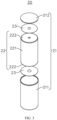
- FIG. 3 is a schematic exploded view of a battery cell according to some embodiments of the present disclosure.
- the battery cell 20 may include a shell assembly 21 and an electrode assembly 22 located in the shell assembly 21.
- the shell assembly 21 includes a housing 211 and an end cap 212.
- the housing 211 is a hollow structure opened at one end.
- the end cap 212 fits on, and is hermetically connected to, the opening of the housing 211, to form a sealed space configured to accommodate the electrode assembly 22.
- the electrode assembly 22 is mounted in the cavity of the housing 211.
- the housing 211 and the end cap 212 may be stand-alone components.
- the end cap 212 fits on the opening of the housing 211 to form an internal environment of the battery cell 20.
- the housing 211 and the end cap 212 may be integrated instead.
- the housing 211 and the end cap 212 may form a common connection face before other components are put into the housing. Subsequently, when the interior of the battery cell 20 needs to be sealed in the housing, the end cap 212 is made to fit the housing 211.
- the housing 211 and the end cap 212 may be made of a variety of materials such as copper, iron, aluminum, stainless steel, aluminum alloy, or plastic. The materials are not particularly limited herein.
- the shell assembly is not limited to the structures enumerated above.
- the shell assembly may be another structure instead.
- the shell assembly includes a housing and two end caps.
- the housing is a hollow structure opened at two opposite ends.
- One end cap fits on, and is hermetically connected to, one corresponding opening of the housing, to form a sealed space configured to accommodate the electrode assembly and an electrolyte.
- the electrode assembly 22 may include a body portion 221 and tab portion 222.
- the tab portion 222 extends from the body portion 221 so that the tab portion 222 protrudes beyond the end portion of the body portion 221.
- the electrode assembly 22 may include a positive electrode plate, a negative electrode plate, and a separator.
- the electrode assembly 22 may be a jelly-roll structure formed by winding the positive electrode plate, the negative electrode plate, and the separator.
- the electrode assembly 22 may be a stacked structure formed by stacking the positive electrode plate, the negative electrode plate, and the separator.
- the positive electrode plate includes a positive current collector and a positive active material layer applied on two opposite sides of the positive current collector.
- the negative electrode plate includes a negative current collector and a negative active material layer applied on two opposite sides of the negative current collector.
- the body portion 221 is a part of the electrode assembly 22, the part corresponds to a region of the electrode plates, and the region is coated with an active material layer.
- the tab portion 222 is a part, uncoated with the active material layer, of the electrode plates.
- the tab portion 222 may be divided into a positive tab portion and a negative tab portion.
- the positive tab portion and the negative tab portion may be disposed at two ends of the body portion 221 respectively or at one end of the body portion 221.
- the battery cell 20 includes an electrolyte solution and a current collecting component 23 in addition to the electrode assembly 22 and the shell assembly 21.
- the electrolyte solution is located in the housing to infiltrate the electrode assembly 22.
- the shell assembly 21 includes an electrode lead-out portion (for example, a housing, an end cap, or an electrode terminal mounted on the housing or end cap) configured to input or output electrical energy.
- the electrode assembly 22 is accommodated in the shell assembly 21.
- the current collecting component 23 is accommodated in the shell assembly 21.
- the current collecting component 23 is configured to connect the electrode lead-out portion of the shell assembly 21 to the tab portion 222 of the electrode assembly 22, so as to implement electrical connection between the tab portion 222 and the electrode lead-out portion.
- the current collecting component 23 may be plate-shaped, referred to as a current collecting plate, to facilitate connection to the tab portion 222 at the end portion of the electrode assembly 22.
- FIG. 4 is a cross-sectional schematic view of a jelly-roll structure of an electrode assembly according to some embodiments of the present disclosure.
- the electrode assembly includes: a first electrode plate 10A and a second electrode plate 10B that are of opposite polarities; and a separator 10C disposed between the first electrode plate 10A and the second electrode plate 10B.
- the first electrode plate 10A, the separator 10C, and the second electrode plate 10B are wound along the winding direction r to form a jelly-roll structure 100, for example, to form a stacked structure in FIG.
- the first electrode plate 10A may be a negative electrode plate or a positive electrode plate.
- the second electrode plate 10B is a positive electrode plate or a negative electrode plate of an opposite polarity to the first electrode plate 10A.
- the jelly-roll structure 100 may form a cylindrical jelly-roll structure after being wound. Accordingly, the housing employed for the battery cell containing the electrode assembly is a cylindrical housing structure.
- the battery cell 10 works primarily by shuttling metal ions between the positive electrode plate and the negative electrode plate.
- the separator 10C may be made of a material such as PP (polypropylene, polypropylene) or PE (polyethylene, polyethylene).
- FIG. 5 is a schematic structural diagram of a first electrode plate, a second electrode plate, and a separator in an electrode assembly according to some embodiments of the present disclosure.
- FIG. 6 is a schematic structural diagram of an electrode assembly according to some embodiments of the present disclosure.
- FIG. 7 is a schematic structural diagram of an electrode assembly according to some other embodiments of the present disclosure.
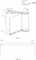
- FIG. 8 is a schematic diagram of an unwound electrode plate in an electrode assembly according to some embodiments of the present disclosure.
- FIG. 9 is a cross-sectional schematic view of an electrode plate in an electrode assembly according to some embodiments of the present disclosure.
- At least one of the first electrode plate 10A or the second electrode plate 10B includes: a current collector (17A, 17B), an active material layer (12A, 12B), and a tab portion (11A, 11B).
- the electrode plate in FIG. 8 and FIG. 9 is a first electrode plate 10A
- the first electrode plate 10A includes a current collector 17A, an active material layer 12A, and a tab portion 11A.
- the active material layer 12A is disposed at least on a surface of the current collector on a side near the separator 10C.
- the second electrode plate 10B includes a current collector 17B, an active material layer 12B, and a tab portion 11B.
- the active material layer 12B is disposed at least on a surface of the current collector on a side near the separator 10C.
- the negative electrode plate includes a current collector (that is, a negative current collector), an active material layer 12A (that is, a negative active material layer), and a tab portion 11A (that is, a negative tab portion).
- the active material layer 12A is applied on a surface of the current collector.
- the negative electrode plate may further include an insulation layer 13A (for example, a ceramic insulation layer) that covers a surface of the current collector and that is located on a side of the active material layer 12A, the side being close to the tab portion 11A.
- the insulation layer 13A prevents the burrs on a cut edge of the negative electrode plate from piercing the separator and causing a short circuit with the positive electrode plate.
- the tab portion 11A is connected to one lateral edge of the current collector, and the lateral edge extends along the winding direction r.
- the tab portion 11A includes two regions, of which one is a continuous region 15A near the active material layer, and the other is a spacing region 14A away from the active material layer.
- the spacing region 14A includes a plurality of tabs 16A spaced apart along the winding direction r.
- the negative current collector may be made of copper, and the negative active material layer may be graphite, silicon, or the like.
- the tab portion 11A may be welded to the lateral edge of the current collector. Alternatively, the tab portion 11A may be formed by die-cutting the current collector.
- the positive electrode plate 10B includes a current collector (that is, a positive current collector), an active material layer 12B (that is, a positive active material layer), and a tab portion 11B (that is, a positive tab portion).
- the active material layer 12B is applied on a surface of the current collector.
- the tab portion 11B is connected to one lateral edge of the current collector, and the lateral edge extends along the winding direction r.
- the tab portion 11B includes two regions, of which one is a continuous region 15B near the active material layer, and the other is a spacing region 14B away from the active material layer.
- the spacing region 14B includes a plurality of tabs 16B spaced apart along the winding direction r.
- the positive current collector may be made of aluminum, and a positive active material layer may be lithium cobalt oxide, lithium iron phosphate, ternary lithium, lithium manganese oxide, or the like.
- the tab portion 11B may be welded to the lateral edge of the current collector.
- the tab portion 11B may be formed by die-cutting the current collector.
- the tab portion 11A of the first electrode plate 10A and the tab portion 11B of the second electrode plate 10B protrude from the end portion of the jelly-roll structure 100, and can be bent and pressed flat by an extrusion head separately, for example, by kneading or smoothing.
- the flattened tab portion is welded to the current collecting component (for example, the current collecting plate 230 in FIG. 7 ).
- the current collecting component for example, the current collecting plate 230 in FIG. 7
- a tab portion 11A and a tab portion 11B are disposed at two ends of the jelly-roll structure 100 respectively.
- the tab portion 11A and the tab portion 11B are welded to the current collecting plate 230 separately after being smoothed or kneaded.
- the tab portion (11A, 11B) includes a continuous region (15A, 15B) and a spacing region (14A, 14B).
- the spacing region (14A, 14B) includes a plurality of tabs (16A, 16B) spaced apart along the winding direction r.
- the tabs (16A, 16B) may be formed by a process such as die-cutting.
- the bending strength of the spacing region (14A, 14B) is significantly lower than the bending strength of the continuous region (15A, 15B), and therefore, the continuous region (15A, 15B) does not significantly yield or bend while the spacing region (14A, 14B) is bent and pressed flat, thereby avoiding excessive nearness of the end face of the tab portion to the separator 10C.
- the excessive nearness is prone to burn the separator 10C in welding the flattened portion (11A, 11B).
- the tab (16A, 16B) located at the end portion of the jelly-roll structure 100 can be less wrinkled when being flattened, thereby maximally eliminating problems such as break of and damage to the tab (16A, 16B) caused by wrinkles of the tab (16A, 16B), and damage to the electrode plate or a short circuit of the electrode plate caused by the wrinkles and bulges of the tab (16A, 16B) inserted into the electrode plate layer.
- the spaced tabs (16A and 16B) overlap each other when being pressed flat, thereby forming a more compacter dense layer, avoiding puncturing in subsequent welding, and improving the welding yield rate.
- the axis of the jelly-roll structure 100 is X.
- the height of the tab portion before bending of the tabs is h0
- the height of each tab before bending of the tab is h1, satisfying: 0.25 ⁇ h1/h0 ⁇ 1.
- the h1/h0 ratio may be equal to 0.25, 0.35, 0.45, 0.55, 0.65, 0.75, 0.85, or 0.95.
- the value range of the h1/h0 ratio is not limited.
- any values are applicable as long as h1 is less than h0.
- the final status of the tab is bent and pressed flat to facilitate connection to the current collecting plate.
- the height h0 of the tab portion and the height h1 of the tabs defined in this embodiment are both the heights before bending of the tabs (16A, 16B), that is, the original heights of the tab portion and the tabs (16A, 16B).
- h0 and h1 may be measured before the tabs (16A, 16B) of the electrode plate are bent.
- the tab portion (11A, 11B) in the jelly-roll structure 100 may be stroked straight to facilitate measurement of h0 and h1.
- the dimensions of the tab portion of at least one of the first electrode plate 10A or the second electrode plate 10B satisfy the above formula.
- the tab portion 11A of the first electrode plate 10A satisfies the above dimensional range
- the tab portion 11B of the second electrode plate 10B satisfies the above dimensional range
- both the tab portion 11A of the first electrode plate 10A and the tab portion 11B of the second electrode plate 10B satisfy the above dimensional range.
- the height h0 of the tab portion reflects an elongation dimension of the tab portion in a direction perpendicular to the lateral edge of the current collector.
- the height h1 of the tab is the height of the spacing region.
- the height h1 of the tab reflects an elongation dimension of the tab along a direction perpendicular to the lateral edge of the current collector.
- the h1/h0 ratio is less than 0.25, then the height of the tab in the spacing region is insufficient, and the thickness of the dense layer formed after the flattening of the tab is insufficient, thereby being prone to the problems such as puncturing during welding. If the h1/h0 ratio is greater than or equal to 1, then the height of the tab is greater than or equal to the entire tab portion, the tab slitting may make the active material coating layer fall off, and the separator is prone to be burned during welding of the flattened tab portion.
- the height relationship between the tab portion and the tab disclosed in this embodiment ensures that the thickness of a dense layer formed after the flattening of the tab meets welding conditions, and also alleviates the problem of detachment of the active material coating layer caused by the slitting of the tab as well as the problem of burning the separator during welding of the tab portion.
- the height of the tab portion before bending of the tabs is h0, and the height of each tab before bending of the tab is h1, satisfying: 0.4 ⁇ h1/h0 ⁇ 0.8.
- the h1/h0 ratio may be equal to 0.4, 0.5, 0.6, 0.7, or 0.8.
- this application can more satisfactorily achieve the desired thickness of the dense layer, alleviate the problem of detachment of the active material coating layer, and avoid the problem of burning the separator during welding, and can more sufficiently satisfy the conditions of welding and tab slitting, and improve the yield rate of prepared electrode assemblies.
- At least a part of the tab is bent and pressed flat against the current collector.
- a maximum distance from a bend line S to a top (free end) of the tab (16A, 16B) is h2, that is, the height of the bent part is h2.
- the height of the tab before bending of the tab is h1, and h1 and h2 satisfy: 0.3 ⁇ h2/h1 ⁇ 1.
- the h2/h1 ratio may be equal to 0.3, 0.4, 0.5, 0.6, 0.7, 0.8, 0.9, or 1.
- the value range of the h2/h1 ratio is not limited.
- the h2/h1 ratio may be greater than 1, that is, the continuous region of the tab portion may yield or bend.
- the dimensions of the tab portion of at least one of the first electrode plate 10A or the second electrode plate 10B satisfy the above formula.
- the tab portion 11A of the first electrode plate 10A satisfies the above dimensional range
- the tab portion 11B of the second electrode plate 10B satisfies the above dimensional range
- both the tab portion 11A of the first electrode plate 10A and the tab portion 11B of the second electrode plate 10B satisfy the above dimensional range.
- the bent and flattened part of the tab is also a part that is used for welding to the current collecting component (such as current collecting plate 20).
- the height h2 of the bent part of the tab affects the yield rate of subsequent welding.
- the h2/h1 ratio is less than 0.3, then the height of the bent portion is insufficient, thereby resulting in an insufficient thickness of the dense layer formed, failing to meet the welding conditions, and being prone to the problems such as puncturing during welding.
- the h2/h1 ratio is greater than 1, then the height of the bent part is greater than the height of the tab before bending. In other words, the continuous region also bends. In this case, the thickness of the dense layer formed by flattening is not increased significantly. Rather, the infiltration performance of the electrolyte solution is adversely affected because the slit between the tabs is maximally compressed.
- the dimensional relationship between the tab and the bent part disclosed in this embodiment ensures that the thickness of the dense layer formed after the flattening of the tab meets the welding conditions, and also improves the infiltration performance of an electrolyte solution, and improves the cycle performance and power performance of the electrolyte solution.
- the jelly-roll structure 100 is a cylindrical jelly-roll structure.
- a diameter of a center roll of the jelly-roll structure 100 is d.
- d is a circumferential diameter of the first tab of the tab portion (11A, 11B) along the winding direction (r) in the corresponding electrode plate layer in the cylindrical jelly-roll structure 100.
- the minimum diameter corresponding to the innermost tab of the jelly-roll structure is d.
- the width of the tab is l, satisfying; 0.7 ⁇ l/d ⁇ 2.
- the width l of the tab reflects the dimension of the tab along the winding direction r.
- the lid ratio may be equal to 0.7, 0.8, 0.9, 1, 1.1, 1.2, 1.3, 1.4, 1.5, 1.6, 1.7, 1.8, 1.9, or 2.
- the dimensions of the tab of at least one of the first electrode plate 10A or the second electrode plate 10B satisfy the above formula.
- the tab 16A of the first electrode plate 10A satisfies the above dimensional range
- the tab 16B of the second electrode plate 10B satisfies the above dimensional range
- both the tab 16A of the first electrode plate 10A and the tab 16B of the second electrode plate 10B satisfy the above dimensional range.
- the lid ratio is less than 0.7, then the width of the tab is undersized, and the tab is prone to be folded and torn when the die-cut tab is being rewound and when a bare cell is being prepared by winding, thereby resulting in a decline in the yield rate or even safety hazards.
- the lid ratio is greater than 2
- the width of the tab is oversized, and the strength of the tab is not reduced effectively (especially in the inner coil and the middle coil of the bare cell), thereby failing to effectively enhance the compactness of the dense layer formed after flattening of the tab, and being prone to poor welding.
- the relationship between the width of the tab and the diameter of the innermost coil of the jelly-roll structure disclosed in this embodiment can ensure that the denseness of the dense layer formed after the flattening of the tab meets the welding conditions, and can also avoid a decline in the yield rate caused by the folding, tearing, and other problems of the tabs occurring during the winding of a bare cell.
- a maximum spacing between adjacent tabs is g, and the width of the tab is l, satisfying: g/l ⁇ 0.2.
- the g/l ratio may be equal to 0.05, 0.10, 0.15, or 0.2.
- the dimensions of the tab of at least one of the first electrode plate 10A or the second electrode plate 10B satisfy the above formula.
- the tab 16A of the first electrode plate 10A satisfies the above dimensional range
- the tab 16B of the second electrode plate 10B satisfies the above dimensional range
- both the tab 16A of the first electrode plate 10A and the tab 16B of the second electrode plate 10B satisfy the above dimensional range.
- the width of the tab is undersized, and the spacing between the tabs is oversized, thereby resulting in an insufficient thickness of the dense layer formed after the flattening, and being prone to reduce the yield rate of welding.
- the relationship between the tab width and the tab spacing disclosed in this embodiment ensures that the thickness of the dense layer formed after the flattening of the tab meets the welding conditions, and improves the welding quality.
- the height of the tab portion before bending of the tabs is h0, satisfying: 3 mm ⁇ h0 ⁇ 8 mm; and/or, the height of the tab before bending of the tab is h1, satisfying: 1 mm ⁇ h1 ⁇ 8 mm; and/or the height of the bent part of the tab is h2, satisfying: 1 mm ⁇ h2 ⁇ 8 mm.
- h0 may be equal to 3 mm, 4 mm, 5 mm, 6 mm, 7 mm, or 8 mm
- h1 may be equal to 1 mm, 2 mm, 3 mm, 4 mm, 5 mm, 6 mm, 7 mm, or 8 mm
- h2 may be equal to 1 mm, 2 mm, 3 mm, 4 mm, 5 mm, 6 mm, 7 mm, or 8 mm.
- the dimensions of the tab portion of at least one of the first electrode plate 10A or the second electrode plate 10B satisfy the above formula.
- the tab portion 11A of the first electrode plate 10A satisfies the above dimensional range
- the tab portion 11B of the second electrode plate 10B satisfies the above dimensional range
- both the tab portion 11A of the first electrode plate 10A and the tab portion 11B of the second electrode plate 10B satisfy the above dimensional range.
- the design of the dimensions of the tab portion, the tabs, and the bent part disclosed in this embodiment makes the flattened tabs overlap each other to form a denser tab layer, and significantly reduces the probability of being punctured by laser welding, thereby improving the welding quality, and also avoiding the problems such as detachment of the active material coating layer and a lower infiltration effect of the electrolyte solution.
- the height of the tab portion before bending of the tabs is h0, satisfying: 4 mm ⁇ h0 ⁇ 7 mm; and/or, the height of the tab before bending of the tab is h1, satisfying: 2 mm ⁇ h1 ⁇ 7 mm; and/or the height of the bent part of the tab is h2, satisfying: 2 mm ⁇ h2 ⁇ 7 mm.
- the dimensions of the tab portion of at least one of the first electrode plate 10A or the second electrode plate 10B satisfy the above formula.
- h0 may be equal to 4 mm, 5 mm, 6 mm, or 7 mm
- h1 may be equal to 2 mm, 3 mm, 4 mm, 5 mm, 6 mm, or 7 mm
- h2 may be equal to 2 mm, 3 mm, 4 mm, 5 mm, 6 mm, or 7 mm.
- the design of the dimensions of the tab portion, the tabs, and the bent part disclosed in this embodiment makes the flattened tabs overlap each other to form a denser tab layer, and significantly reduces the probability of being punctured by laser welding, thereby further improving the welding quality, and more effectively avoiding the problems such as detachment of the active material coating layer and a lower infiltration effect of the electrolyte solution.
- FIG. 10 is a schematic diagram of an unwound electrode plate in an electrode assembly according to some other embodiments of the present disclosure.
- the tabs (16A, 16B) of the electrode plates (10A, 10B) are inclined to one lateral edge of the current collector, and the lateral edge extends along the winding direction.
- At least one of the tab 16A of the first electrode plate 10A or the tab 16B of the second electrode plate 10B is inclined.
- the tab 16A of the first electrode plate 10A is inclined, or the tab 16B of the second electrode plate 10B is inclined, or both the tab 16A of the first electrode plate 10A and the tab 16B of the second electrode plate 10B are inclined.
- tabs extend vertical to the lateral edge of the current collector.
- the tabs do not extend vertically, but extend at an inclination to the lateral edge of the current collector.
- the tabs of the electrode plate extend at an inclination to the lateral edge of the current collector, thereby further reducing the strength of the tabs in the spacing region, making it easier to press the tabs flat, improving the denseness and thickness of the dense layer formed after the tabs are pressed flat, and improving the yield rate of welding.
- the inclination angles ⁇ of the tabs (16A, 16B) satisfy: 45° ⁇ ⁇ ⁇ 90°.
- ⁇ may be equal to 45°, 55°, 65°, 75°, or 85°.
- the inclination angle of at least one of the tab 16A of the first electrode plate 10A or the tab 16B of the second electrode plate 10B meets the above condition.
- the inclination angle of the tab 16A of the first electrode plate 10A meets the above condition
- the inclination angle of the tab 16B of the second electrode plate 10B meets the above condition
- both the inclination angles of both the tab 16A of the first electrode plate 10A and the tab 16B of the second electrode plate 10B satisfy the above condition.
- the inclination angle of the tab is less than 45°, the bending strength of the tab is not reduced effectively. Rather, the tab is made more prone to be folded and broken.
- the inclination angle ⁇ of the tabs disclosed in this embodiment can effectively reduce the bending strength of the tabs, make it easier to press the tabs flat, and effectively avoid the problems of folding and breaking the tabs during the winding and/or flattening.
- FIG. 11 is a schematic structural diagram of an electrode assembly according to some other embodiments of the present disclosure. As shown in FIG. 11 , according to some embodiments of this application, the inclination direction of the tabs (16A, 16B) in the electrode plates (10A, 10B) is opposite to the winding direction r of the electrode plates (10A, 10B).
- At least one of the tab 16A of the first electrode plate 10A or the tab 16B of the second electrode plate 10B is inclined and the inclination direction is opposite to the winding direction r.
- both the tab 16A of the first electrode plate 10A and the tab 16B of the second electrode plate 10B are inclined, and the inclination direction of both tabs is opposite to the winding direction r.
- the tabs With the inclination direction of the tabs being opposite to the winding direction of the electrode plate, the tabs is less prone to be folded and broken during winding of the electrode plate, thereby improving the yield rate of the j elly-roll structure.
- the bent part of the tabs (16A, 16B) is bent and pressed flat by an extrusion head 1000 that rotates and squeezes.
- the extrusion head 1000 rotates along the rotation direction o to knead or smooth the bent part of the tabs (16A, 16B).
- the inclination direction of the tabs (16A, 16B) is identical to the rotation direction o of the extrusion head 1000.
- At least one of the tab 16A of the first electrode plate 10A or the tab 16B of the second electrode plate 10B is inclined and the inclination direction is identical to the rotation direction o of the extrusion head 1000.
- both the tab 16A of the first electrode plate 10A and the tab 16B of the second electrode plate 10B are inclined, and the inclination direction of both tabs is identical to the rotation direction o of the extrusion head 1000.
- this application avoids damage to the tabs (16A, 16B) during the flattening, especially the tabs (16A, 16B) at the outer coil and the ending of the jelly-roll structure 100, and improves the yield rate of the jelly-roll structure 100.
- the rotation direction o of the extrusion head 1000 is opposite to the winding direction r of the jelly-roll structure, and the inclination direction of the tabs (16A, 16B) is identical to the rotation direction o of the extrusion head 1000 and opposite to the winding direction r of the jelly-roll structure.
- the tabs (16A, 16B) are prevented from being folded and broken during winding of the electrode plates (10A, 10B), and the tabs (16A, 16B) are prevented from being damaged during flattening of the tabs (16A, 16B), thereby improving the yield rate of the j elly-roll structure.
- FIG. 12 is a schematic diagram of an unwound electrode plate in an electrode assembly according to some other embodiments of the present disclosure.
- a bevel edge Q formed by cutting a corner is disposed on an ending side of a tab (160A, 160B) located at an ending of the jelly-roll structure.
- the corner of the tab (160A, 160B) at the ending of the electrode plate may be directly cut away when the electrode plate (10A, 10B) is cut off to terminate the winding, so as to form a bevel edge Q at the ending end of the tab.
- the bevel edge Q is disposed on at least one of the tab 160A of the first electrode plate 10A or the tab 160B of the second electrode plate 10B, both tabs being located at the ending of the jelly-roll structure.
- the bevel edge Q may be disposed on the tab 160A of the first electrode plate 10A at the ending of the jelly-roll structure, or the bevel edge Q may be disposed on the tab 160B of the second electrode plate 10B at the ending of the jelly-roll structure, or the bevel edge Q may be disposed on both the tab 160A of the first electrode plate 10A at the ending of the j elly-roll structure and the tab 160B of the second electrode plate 10B at the ending of the j elly-roll structure.
- the tab at the ending of the electrode plate is die-cut to cut away the corner at the ending end of the tab, thereby alleviating such problems effectively.
- the bevel edge Q of the tab (160A, 160B) located at the ending of the j elly-roll structure is at least partially arc-shaped.
- the corner of the tab (160A, 160B) at the ending of the electrode plate is die-cut arcuately to form an arc-shaped bevel edge Q.
- the arc-shaped bevel edge Q is disposed on at least one of the tab 160A of the first electrode plate 10A or the tab 160B of the second electrode plate 10B, both tabs being located at the ending of the jelly-roll structure.
- the arc-shaped bevel edge Q may be disposed on the tab 160A of the first electrode plate 10A at the ending of the j elly-roll structure, or the arc-shaped bevel edge Q may be disposed on the tab 160B of the second electrode plate 10B at the ending of the jelly-roll structure, or the arc-shaped bevel edge Q may be disposed on both the tab 160A of the first electrode plate 10A at the ending of the j elly-roll structure and the tab 160B of the second electrode plate 10B at the ending of the j elly-roll structure.
- the bevel edge formed by die-cutting the corner of the tab is not limited to being arc-shaped, but may be in other shapes such as rectilinear.
- a tab shaping apparatus is further provided. As shown in FIG. 11 , the tab shaping apparatus includes an extrusion head 1000.
- the extrusion head 1000 is configured to smooth the tabs (16A; 16B) in the electrode assembly according to any one of the above embodiments so that at least a part of each tab (16A; 16B) is bent and pressed flat against the current collector.
- the bent part of the tab (16A, 16B) is bent and pressed flat by an extrusion head 1000 that rotates and squeezes.
- the tabs (16A, 16B) are inclined to one lateral edge of the current collector, and the lateral edge extends along the winding direction r.
- the extrusion head 1000 rotates along the rotation direction o to knead or smooth the bent part of the tabs (16A, 16B).
- the rotation direction o of the extrusion head 1000 is configured to be identical to the inclination direction of the tabs (16A, 16B).
- this application avoids damage to the tabs (16A, 16B) during the flattening, especially the tabs (16A, 16B) at the outer coil and the ending of the jelly-roll structure 100, and improves the yield rate of the jelly-roll structure 100.
- the tab shaping apparatus may further include other structures, such as a driving mechanism configured to drive the extrusion head to move.
- Other structures are not limited herein.
- a battery cell is further provided.
- the battery cell includes the electrode assembly according to any one of the above embodiments.
- FIG. 2B is a schematic diagram of a connection structure of a plurality of battery cells 20, where each battery cell 20 includes the electrode assembly according to any one of the preceding embodiments.
- the electrode assembly 22 is the electrode assembly according to any one of the preceding embodiments.
- the battery cell containing the electrode assembly disclosed above exhibits superior performance, such as higher safety and a higher yield rate of products.
- At least a part of the tab is bent and pressed flat against the current collector.
- a maximum distance from a bend line to a top of the tab is h2.
- the jelly-roll structure is a cylindrical jelly-roll structure.
- the electrode assembly further includes a current collecting plate. The current collecting plate is located on one side of the cylindrical jelly-roll structure, the side being connected to the tab portion, and is fixedly connected to the bent part of the tab by welding.
- the jelly-roll structure 100 is a cylindrical jelly-roll structure.
- a tab portion 13A and a tab portion 13B are disposed at two ends of the jelly-roll structure 100 respectively.
- the tab portion 13A and the tab portion 13B are welded to the current collecting plate 230 separately after being bent and smoothed.
- the reference numeral 231 represents the welding region 231 on the current collecting plate 20.
- the thickness of the current collecting plate 20 is t1
- the height of the bent part of the tab is h2
- t1 and h2 satisfy: 0.05 ⁇ t1/h2 ⁇ 0.2.
- the dimensions of the bent part of the tab of at least one of the first electrode plate 10A or the second electrode plate 10B satisfy the above formula.
- the bent part of the tab 16A of the first electrode plate 10A satisfies the above dimensional range
- the bent part of the tab 16B of the second electrode plate 10B satisfies the above dimensional range
- both the bent part of the tab 16A of the first electrode plate 10A and the bent part of the tab 16B of the second electrode plate 10B satisfy the above dimensional range.
- the t1/h2 ratio is less than 0.05, then the height of the bent part is excessive, and the thickness of the dense layer formed after the flattening of the tab is excessive, thereby reducing the capacity of the battery. If the t1/h2 ratio is greater than 0.2, the height of the bent part is deficient, thereby resulting in deficiency of the thickness of the dense layer formed after the flattening, failing to meet the welding conditions, and being prone to problems such as puncturing during welding.
- the relationship between the height of the bent part of the tab and the thickness of the current collecting plate disclosed in this embodiment ensures that the thickness of the dense layer formed after the flattening of the tab meets the welding conditions, and also increases the capacity of the battery.
- a battery 30 is further provided.
- the battery includes the battery cell 20 according to any one of the preceding embodiments.
- the battery 30 containing the battery cell 20 exhibits superior performance, such as higher safety and a higher yield rate of products.
- an electrical device is further provided.
- the electrical device includes the battery 30 according to any one of the above embodiments.
- the electrical device may be any one of the electrical devices described above in which a battery needs to be used, for example, an electrically powered device or an energy storage device.
- the electrical device in FIG. 1 is a vehicle.
- the electrical device that employs the battery disclosed above exhibits superior performance, such as higher safety and reliability.
- some embodiments of the present disclosure provide an electrode assembly, including: a first electrode plate 10A and a second electrode plate 10B that are of opposite polarities; and a separator 10C disposed between the first electrode plate 10A and the second electrode plate 10B.
- the first electrode plate 10A, the separator 10C, and the second electrode plate 10B are wound along the winding direction r to form a jelly-roll structure 100.
- the first electrode plate 10A is a negative electrode plate
- the second electrode plate 10B is a positive electrode plate of an opposite polarity to the first electrode plate 10A.
- the jelly-roll structure 100 forms a cylindrical jelly-roll structure after being wound.
- the first electrode plate 10A includes a current collector 17A (that is, a negative current collector), an active material layer 12A (that is, a negative active material layer), and a tab portion 11A (that is, a negative tab portion), and further includes an insulation layer 13A (for example, a ceramic insulation layer) that covers a surface of the current collector 17A and that is located on a side of the active material layer 12A, the side being close to the tab portion 11A.
- the tab portion 11A is connected to one lateral edge of the current collector 17A, and the lateral edge extends along the winding direction r.
- the tab portion 11A includes a continuous region 15A near the active material layer and a spacing region 14A away from the active material layer.
- the spacing region 14A includes a plurality of tabs 16A spaced apart along the winding direction r.
- the second electrode plate 10B includes a current collector 17B (that is, a positive current collector), an active material layer 12B (that is, a positive active material layer), and a tab portion 11B (that is, a positive tab portion).
- the tab portion 11B is connected to one lateral edge of the current collector 17B, and the lateral edge extends along the winding direction r.
- the tab portion 11B includes a continuous region 15B near the active material layer and a spacing region 14B away from the active material layer.
- the spacing region 14B includes a plurality of tabs 16B spaced apart along the winding direction r.
- the tab portion 11A of the first electrode plate 10A and the tab portion 11B of the second electrode plate 10B protrude from the two ends of the jelly-roll structure 100 respectively.
- the tab 16A of the tab portion 11A and the tab 16B of the tab portion 11B are squeezed and pressed flat by the extrusion head 1000 respectively.
- the flattened tab 16A and tab 16B are welded to the current collecting plate 230 separately.
- Both the tab portion 11A of the first electrode plate 10A and the tab portion 11B of the second electrode plate 10B satisfy the following dimensional settings: as shown in FIG. 8 , in the axial direction of the j elly-roll structure, the height h0 of the tab portion before the bending of the tabs, the height h1 of the tab before the bending of the tab, and the height h2 of a to-be-bent-and-flattened part of the tab portion satisfy the following conditions: h0 satisfies: 4 mm ⁇ h0 ⁇ 7 mm; h1 satisfies: 2 mm ⁇ h1 ⁇ 7 mm; h2 satisfies: 2 mm ⁇ h2 ⁇ 7 mm; 0.25 ⁇ h1/h0 ⁇ 1; and 0.3 ⁇ h2/h1 ⁇ 1.
- the tab 16A of the first electrode plate 10A and the tab 16B of the second electrode plate 10B are both inclined in a manner satisfying the following conditions: the inclination direction is opposite to the winding direction r of the jelly-roll structure and identical to the rotation direction o of the extrusion head 1000, and the inclination angle ⁇ satisfies 45° ⁇ ⁇ ⁇ 90°.
Landscapes
- Chemical & Material Sciences (AREA)
- Chemical Kinetics & Catalysis (AREA)
- Electrochemistry (AREA)
- General Chemical & Material Sciences (AREA)
- Engineering & Computer Science (AREA)
- Manufacturing & Machinery (AREA)
- Materials Engineering (AREA)
- Connection Of Batteries Or Terminals (AREA)
Applications Claiming Priority (1)
| Application Number | Priority Date | Filing Date | Title |
|---|---|---|---|
| PCT/CN2022/117329 WO2024050697A1 (fr) | 2022-09-06 | 2022-09-06 | Ensemble électrode, cellule de batterie, batterie, dispositif électrique et appareil de mise en forme de languette |
Publications (2)
| Publication Number | Publication Date |
|---|---|
| EP4510364A1 true EP4510364A1 (fr) | 2025-02-19 |
| EP4510364A4 EP4510364A4 (fr) | 2025-07-30 |
Family
ID=90192700
Family Applications (1)
| Application Number | Title | Priority Date | Filing Date |
|---|---|---|---|
| EP22957671.5A Pending EP4510364A4 (fr) | 2022-09-06 | 2022-09-06 | Ensemble électrode, cellule de batterie, batterie, dispositif électrique et appareil de mise en forme de languette |
Country Status (4)
| Country | Link |
|---|---|
| US (1) | US20250070219A1 (fr) |
| EP (1) | EP4510364A4 (fr) |
| CN (1) | CN118556338A (fr) |
| WO (1) | WO2024050697A1 (fr) |
Families Citing this family (4)
| Publication number | Priority date | Publication date | Assignee | Title |
|---|---|---|---|---|
| CN222462923U (zh) * | 2024-03-28 | 2025-02-11 | 比亚迪股份有限公司 | 极片、电池及用电设备 |
| CN118472567A (zh) * | 2024-05-28 | 2024-08-09 | 惠州亿纬锂能股份有限公司 | 极片、卷芯、圆柱电池及电池包 |
| CN223539651U (zh) * | 2024-10-17 | 2025-11-11 | 株式会社Aesc日本 | 二次电池、电池组及电子装置 |
| CN119381145B (zh) * | 2024-10-28 | 2025-08-08 | 无锡德润电子有限公司 | 背胶铜箔的背胶翻折工艺系统及背胶铜箔变压器 |
Family Cites Families (8)
| Publication number | Priority date | Publication date | Assignee | Title |
|---|---|---|---|---|
| JP4305035B2 (ja) * | 2003-04-17 | 2009-07-29 | 新神戸電機株式会社 | 捲回式円筒型リチウムイオン電池 |
| KR101002487B1 (ko) * | 2008-06-23 | 2010-12-17 | 삼성에스디아이 주식회사 | 전극조립체 및 이를 포함하는 이차전지 |
| JP2014022102A (ja) * | 2012-07-13 | 2014-02-03 | Toyota Industries Corp | 蓄電装置及び二次電池並びに電極の製造方法 |
| CA3202317A1 (fr) * | 2021-01-19 | 2022-07-28 | Lg Energy Solution, Ltd. | Batterie, collecteur de courant applique a celle-ci, et bloc-batterie et vehicule les comprenant |
| CN113193165B (zh) * | 2021-05-28 | 2023-06-06 | 微宏动力系统(湖州)有限公司 | 极耳极片及卷绕电池 |
| CN113488746A (zh) * | 2021-07-06 | 2021-10-08 | 湖北亿纬动力有限公司 | 一种多极耳电芯的制作工艺及多极耳电芯 |
| CN114156545A (zh) * | 2021-10-22 | 2022-03-08 | 天津空间电源科技有限公司 | 一种阶梯式一体成型极耳卷绕式锂离子电池及其制备方法 |
| CN217062176U (zh) * | 2022-03-21 | 2022-07-26 | 珠海冠宇电池股份有限公司 | 一种极片和电池 |
-
2022
- 2022-09-06 CN CN202280089801.2A patent/CN118556338A/zh active Pending
- 2022-09-06 WO PCT/CN2022/117329 patent/WO2024050697A1/fr not_active Ceased
- 2022-09-06 EP EP22957671.5A patent/EP4510364A4/fr active Pending
-
2024
- 2024-11-12 US US18/945,497 patent/US20250070219A1/en active Pending
Also Published As
| Publication number | Publication date |
|---|---|
| WO2024050697A1 (fr) | 2024-03-14 |
| US20250070219A1 (en) | 2025-02-27 |
| EP4510364A4 (fr) | 2025-07-30 |
| CN118556338A (zh) | 2024-08-27 |
Similar Documents
| Publication | Publication Date | Title |
|---|---|---|
| EP4510364A1 (fr) | Ensemble électrode, cellule de batterie, batterie, dispositif électrique et appareil de mise en forme de languette | |
| EP4131631B1 (fr) | Ensemble électrode, élément de batterie, batterie et appareil consommateur d'énergie | |
| CN218769985U (zh) | 电极组件、电池单体、电池、用电装置和极耳整形装置 | |
| US20230216077A1 (en) | Spirally wound electrode assembly, battery cell, battery and electric apparatus | |
| EP4333193A1 (fr) | Élément de batterie ainsi que son procédé et son appareil de fabrication, batterie et dispositif électrique | |
| CN115777157B (zh) | 卷绕式电极组件、电池单体、电池及用电设备 | |
| US20240055646A1 (en) | Wound electrode assembly, battery cell, battery, and electrical device | |
| US20260018712A1 (en) | Battery cell case and manufacturing method therefor, battery cell, battery, and electric apparatus | |
| EP4120463A1 (fr) | Batterie, appareil électrique, et procédé et dispositif de fabrication de batterie | |
| US20260045607A1 (en) | Battery cell, battery, and electric device | |
| US20240363889A1 (en) | Electrode assembly, battery cell, battery, and electric device | |
| US20240332538A1 (en) | Electrode assembly, battery cell, battery and power consuming device | |
| EP4641822A1 (fr) | Cellule de batterie, batterie et dispositif électrique | |
| US20230223642A1 (en) | Pressure relief apparatus, battery cell, battery, and electrical device | |
| US20250364705A1 (en) | Electrode assembly, manufacturing method for electrode assembly, battery and electrical apparatus | |
| EP4068414A1 (fr) | Ensemble électrode, élément de batterie, batterie, et dispositif et procédé de fabrication pour ensemble électrode | |
| EP4557499A1 (fr) | Feuille d'électrode, ensemble électrode, élément de batterie, batterie et dispositif électrique | |
| CN117996378A (zh) | 电池单体、电池及用电装置 | |
| CN222775554U (zh) | 电池单体、电池及用电装置 | |
| CN223956569U (zh) | 极片、二次电池及电子装置 | |
| CN223858396U (zh) | 电芯、电池装置及用电设备 | |
| CN119497932B (en) | Battery monomer, battery and electric equipment | |
| CN222953324U (zh) | 电池单体、电池及用电装置 | |
| CN220774658U (zh) | 连接件、电池模组、电池、用电设备和储能设备 | |
| EP4447203B1 (fr) | Élément de batterie et son procédé de fabrication, batterie et dispositif électrique |
Legal Events
| Date | Code | Title | Description |
|---|---|---|---|
| STAA | Information on the status of an ep patent application or granted ep patent |
Free format text: STATUS: THE INTERNATIONAL PUBLICATION HAS BEEN MADE |
|
| PUAI | Public reference made under article 153(3) epc to a published international application that has entered the european phase |
Free format text: ORIGINAL CODE: 0009012 |
|
| STAA | Information on the status of an ep patent application or granted ep patent |
Free format text: STATUS: REQUEST FOR EXAMINATION WAS MADE |
|
| 17P | Request for examination filed |
Effective date: 20241111 |
|
| AK | Designated contracting states |
Kind code of ref document: A1 Designated state(s): AL AT BE BG CH CY CZ DE DK EE ES FI FR GB GR HR HU IE IS IT LI LT LU LV MC MK MT NL NO PL PT RO RS SE SI SK SM TR |
|
| A4 | Supplementary search report drawn up and despatched |
Effective date: 20250701 |
|
| RIC1 | Information provided on ipc code assigned before grant |
Ipc: H01M 50/533 20210101AFI20250625BHEP Ipc: H01M 50/538 20210101ALI20250625BHEP Ipc: H01M 4/70 20060101ALI20250625BHEP Ipc: H01M 10/0587 20100101ALI20250625BHEP Ipc: H01M 10/04 20060101ALI20250625BHEP Ipc: H01M 10/052 20100101ALI20250625BHEP Ipc: H01M 10/054 20100101ALI20250625BHEP |
|
| DAV | Request for validation of the european patent (deleted) | ||
| DAX | Request for extension of the european patent (deleted) |