EP4510370A1 - Module de batterie - Google Patents
Module de batterie Download PDFInfo
- Publication number
- EP4510370A1 EP4510370A1 EP23812224.6A EP23812224A EP4510370A1 EP 4510370 A1 EP4510370 A1 EP 4510370A1 EP 23812224 A EP23812224 A EP 23812224A EP 4510370 A1 EP4510370 A1 EP 4510370A1
- Authority
- EP
- European Patent Office
- Prior art keywords
- terminal
- battery module
- cell stack
- body part
- cover
- Prior art date
- Legal status (The legal status is an assumption and is not a legal conclusion. Google has not performed a legal analysis and makes no representation as to the accuracy of the status listed.)
- Granted
Links
Images


Classifications
-
- H—ELECTRICITY
- H01—ELECTRIC ELEMENTS
- H01M—PROCESSES OR MEANS, e.g. BATTERIES, FOR THE DIRECT CONVERSION OF CHEMICAL ENERGY INTO ELECTRICAL ENERGY
- H01M50/00—Constructional details or processes of manufacture of the non-active parts of electrochemical cells other than fuel cells, e.g. hybrid cells
- H01M50/50—Current conducting connections for cells or batteries
- H01M50/572—Means for preventing undesired use or discharge
- H01M50/584—Means for preventing undesired use or discharge for preventing incorrect connections inside or outside the batteries
- H01M50/59—Means for preventing undesired use or discharge for preventing incorrect connections inside or outside the batteries characterised by the protection means
- H01M50/591—Covers
-
- H—ELECTRICITY
- H01—ELECTRIC ELEMENTS
- H01M—PROCESSES OR MEANS, e.g. BATTERIES, FOR THE DIRECT CONVERSION OF CHEMICAL ENERGY INTO ELECTRICAL ENERGY
- H01M50/00—Constructional details or processes of manufacture of the non-active parts of electrochemical cells other than fuel cells, e.g. hybrid cells
- H01M50/20—Mountings; Secondary casings or frames; Racks, modules or packs; Suspension devices; Shock absorbers; Transport or carrying devices; Holders
- H01M50/204—Racks, modules or packs for multiple batteries or multiple cells
- H01M50/207—Racks, modules or packs for multiple batteries or multiple cells characterised by their shape
- H01M50/211—Racks, modules or packs for multiple batteries or multiple cells characterised by their shape adapted for pouch cells
-
- H—ELECTRICITY
- H01—ELECTRIC ELEMENTS
- H01M—PROCESSES OR MEANS, e.g. BATTERIES, FOR THE DIRECT CONVERSION OF CHEMICAL ENERGY INTO ELECTRICAL ENERGY
- H01M50/00—Constructional details or processes of manufacture of the non-active parts of electrochemical cells other than fuel cells, e.g. hybrid cells
- H01M50/20—Mountings; Secondary casings or frames; Racks, modules or packs; Suspension devices; Shock absorbers; Transport or carrying devices; Holders
- H01M50/271—Lids or covers for the racks or secondary casings
-
- H—ELECTRICITY
- H01—ELECTRIC ELEMENTS
- H01M—PROCESSES OR MEANS, e.g. BATTERIES, FOR THE DIRECT CONVERSION OF CHEMICAL ENERGY INTO ELECTRICAL ENERGY
- H01M50/00—Constructional details or processes of manufacture of the non-active parts of electrochemical cells other than fuel cells, e.g. hybrid cells
- H01M50/20—Mountings; Secondary casings or frames; Racks, modules or packs; Suspension devices; Shock absorbers; Transport or carrying devices; Holders
- H01M50/289—Mountings; Secondary casings or frames; Racks, modules or packs; Suspension devices; Shock absorbers; Transport or carrying devices; Holders characterised by spacing elements or positioning means within frames, racks or packs
-
- H—ELECTRICITY
- H01—ELECTRIC ELEMENTS
- H01M—PROCESSES OR MEANS, e.g. BATTERIES, FOR THE DIRECT CONVERSION OF CHEMICAL ENERGY INTO ELECTRICAL ENERGY
- H01M50/00—Constructional details or processes of manufacture of the non-active parts of electrochemical cells other than fuel cells, e.g. hybrid cells
- H01M50/20—Mountings; Secondary casings or frames; Racks, modules or packs; Suspension devices; Shock absorbers; Transport or carrying devices; Holders
- H01M50/296—Mountings; Secondary casings or frames; Racks, modules or packs; Suspension devices; Shock absorbers; Transport or carrying devices; Holders characterised by terminals of battery packs
-
- H—ELECTRICITY
- H01—ELECTRIC ELEMENTS
- H01M—PROCESSES OR MEANS, e.g. BATTERIES, FOR THE DIRECT CONVERSION OF CHEMICAL ENERGY INTO ELECTRICAL ENERGY
- H01M50/00—Constructional details or processes of manufacture of the non-active parts of electrochemical cells other than fuel cells, e.g. hybrid cells
- H01M50/50—Current conducting connections for cells or batteries
- H01M50/572—Means for preventing undesired use or discharge
- H01M50/584—Means for preventing undesired use or discharge for preventing incorrect connections inside or outside the batteries
- H01M50/59—Means for preventing undesired use or discharge for preventing incorrect connections inside or outside the batteries characterised by the protection means
- H01M50/593—Spacers; Insulating plates
-
- Y—GENERAL TAGGING OF NEW TECHNOLOGICAL DEVELOPMENTS; GENERAL TAGGING OF CROSS-SECTIONAL TECHNOLOGIES SPANNING OVER SEVERAL SECTIONS OF THE IPC; TECHNICAL SUBJECTS COVERED BY FORMER USPC CROSS-REFERENCE ART COLLECTIONS [XRACs] AND DIGESTS
- Y02—TECHNOLOGIES OR APPLICATIONS FOR MITIGATION OR ADAPTATION AGAINST CLIMATE CHANGE
- Y02E—REDUCTION OF GREENHOUSE GAS [GHG] EMISSIONS, RELATED TO ENERGY GENERATION, TRANSMISSION OR DISTRIBUTION
- Y02E60/00—Enabling technologies; Technologies with a potential or indirect contribution to GHG emissions mitigation
- Y02E60/10—Energy storage using batteries
Definitions
- the present invention relates to a battery module, and more particularly, to a battery module including a plurality of cells.
- Batteries storing electrical energy may be generally classified into primary batteries and secondary batteries.
- a primary battery is a disposable consumable battery.
- a secondary battery is a chargeable battery that is manufactured by using a material in which oxidation and reduction processes between current and the material are capable of being repeated. That is, when the reduction reaction to the material is performed by the current, power is charged. When the oxidation reaction to the material is performed by the current, power is discharged. Such charging-discharging are repeatedly performed to generate electricity.
- the battery module may include an insulating structure for insulating an assembly of cells disposed therein from a member such as a frame.
- the insulating structure may require a configuration for preventing short circuit from occurring in a terminal exposed to the outside of the battery in addition to a configuration that is disposed inside the battery module to insulate the assembly of the cells from the frame.
- the insulating structure for preventing the short circuit of the terminal from occurring is a separate component, it was not easy to be stored and was likely to be lost when being separated. In addition, there was also a problem in that it is difficult to be applied to various types of terminals.
- the battery module including a different type of separating structure is required.
- an object of the present invention is to provide a battery module including an insulating member that is provided as a configuration capable of preventing short circuit of a terminal from occurring, has no risk of loss, is capable of being applied to various types of terminals, and is reusable for other products even after a lifespan of the battery module is over.
- the battery module according to the present invention includes the cell stack, in which the plurality of cells are stacked, the body part surrounding the cell stack, the endplate blocking the opening of the body part and disposed on the front and rear surfaces of the cell stack, and the insulating member disposed between the cell stack and the body part, and the insulating member includes the terminal cover having the shape extending to the outside of the body part.
- the body part may include: a top plate disposed above the cell stack; and a frame configured to surround bottom and side surfaces of the cell stack.
- the cell stack may include a terminal extending to the outside of the body part so as to be electrically connected to the outside, and the endplate comprises a terminal frame disposed below the terminal.
- the terminal cover may have the same width as a width of the terminal frame.
- the terminal cover may be configured to surround opened top and front surfaces of the terminal.
- the terminal cover may be configured to open the top and front surfaces of the terminal, which are surrounded, so as to be in contact with the outside.
- the terminal cover may include: a horizontal portion extending in a direction parallel to an extension direction of the terminal to surround the opened top surface of the terminal; and a vertical portion extending in a direction perpendicular to the horizontal portion to surround the opened front surface of the terminal.
- the terminal cover may have a shape corresponding to that of the terminal.
- the terminal cover may include an elastic material so that a shape thereof is deformed and restored.
- the terminal cover When force is applied, the terminal cover may be deformed, and the deformed shape may be maintained.
- the insulating member may include an insulating film.
- a battery module includes: a cell stack including a plurality of cells and a terminal protruding in a direction away from the cells so that the cells are electrically connected to the outside; a body part having a shape of which both ends in a longitudinal direction of the cell stack are opened so that the cell stack is accommodated; and an insulating member configured to insulate the cell stack, wherein the insulating member includes: an upper plate disposed between a top surface of the cell stack and the body part to insulate the cell stack from the body part; and a terminal cover extending from the upper plate in a direction away from the cell stack to cover the terminal.
- the terminal cover may have a melting point higher than that of the terminal.
- the battery module may further include an endplate configured to block both the opened ends of the body part and having a through-hole, through which the terminal passes, at a position corresponding to that of the terminal.
- the terminal cover may pass through the through-hole to cover the terminal.
- the battery module according to the present invention may include the cell stack, in which the plurality of cells are stacked, the body part surrounding the cell stack, the endplate blocking the opening of the body part and disposed on the front and rear surfaces of the cell stack, and the insulating member disposed between the cell stack and the body part, and the insulating member may include the terminal cover having the shape extending to the outside of the body part.
- the insulating member may be provided as the configuration capable of preventing the short circuit of the terminal from occurring, have no risk of loss, be capable of being applied to the various types of terminals, and be reusable for other products even after the lifespan of the battery module is over.
- the separate components may be coupled as one component to improve the efficiency and efficiency of the operation and the manufacturing process.
- the present invention provides a battery module as Embodiment 1.
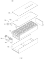
- FIG. 1 is a schematic exploded perspective view of a battery module 100 according to Embodiment 1 of the present invention.
- the battery module 100 may include a cell stack 110, a body part, an endplate 140, and an insulating member 150.
- the cell stack 110 of the battery module 100 may be provided by stacking a plurality of cells.
- Each of the cells may mean one secondary battery, and here, the cell may be a pouch cell.
- the cell stack 110 may be provided by stacking the plurality of cells side by side so as to be parallel to each other.
- the cell stack 110 may generate electrical energy of the battery module 100.
- the cell stack 110 of the battery module 100 according to Embodiment 1 of the present invention may include a terminal 111.
- the terminal 111 may be provided to extend to the outside of the body part for electrical connection to the outside. Specifically, the terminal 111 may extend to the outside of the frame 130 to be described later. More specifically, the terminal 111 may have a shape extending in a direction that is away from the body.
- the terminals 111 according to Embodiment 1 of the present invention may be provided in a pair, which are provided as a negative electrode and a positive electrode, respectively. Also, the terminal 111 may have an approximate rectangular parallelepiped shape.
- the body part of the battery module 100 may be provided to surround the cell stack 110.
- the body part may include a top plate 120 and a frame 130.
- the top plate 120 provided in the body part may be disposed above the cell stack 110.
- the top plate 120 may have a substantially rectangular parallelepiped plate shape, and a surface of the top plate 120, which faces the cell stack 110, may have approximately the same area as the bottom surface of the frame 130.
- the cell stack 110 may be protected from the outside by the top plate 120.
- the cell stack 110 may be disposed inside the frame 130 provided in the body part.
- the frame 130 may be disposed to surround a bottom surface and a side surface of the cell stack 110.
- the frame 130 according to Embodiment 1 of the present invention may have a U-shape when viewed from the front.
- the cell stack 110 may be disposed inside the battery module 100 while being maintained its shape by the frame 130 and may be protected from the outside.
- the endplate 140 of the battery module 100 may be disposed on front and rear surfaces of the cell stack 110 while blocking an opening of the frame 130 in which the cell stack 110 is disposed.
- the endplate 140 may have a substantially rectangular parallelepiped plate shape on the whole and may be formed as a pair that are respectively disposed on the front and rear surfaces of the cell stack 110.
- the cell stack 110 may be protected from the outside by the endplate 140.
- the endplate 140 of the battery module 100 according to Embodiment 1 of the present invention may include a terminal frame 141.
- the terminal frame 141 may be disposed below the terminal 111 and may be provided in a form surrounding a bottom surface and a portion of a side surface of the terminal 111. That is, the terminal frame 141 of the endplate 140 may be a disposed at a position at which the protruding terminal 111 of the cell stack 110 is disposed.
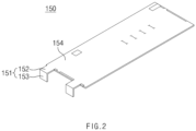
- FIG. 2 is a schematic perspective view illustrating the insulating member 150 of the battery module 100 according to Embodiment 1 of the present invention
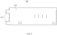
- FIG. 3 is a schematic plan view illustrating the insulating member 150 of the battery module 100 when viewed from the above according to Embodiment 1 of the present invention
- FIG. 4 is a schematic perspective view illustrating a state in which a terminal cover 151 of the insulating member 150 is disposed on the terminal 111 according to Embodiment 1 of the present invention.
- the battery module 100 may include an insulating structure for preventing defects, which may occur while electricity flows between the cells disposed therein and other components, from occurring.
- the battery module 100 according to Embodiment 1 of the present invention may include the insulating member 150.
- the insulating member 150 may be provided in the form of a thin plate having insulating properties, and the insulating member 150 may be an insulating film. In addition, the insulating member 150 may be disposed on an outer surface of the cell stack 110.
- the insulating member 150 of the battery module 100 according to Embodiment 1 of the present invention includes an upper plate 154 and a terminal cover 151.
- the upper plate 154 of the insulating member 150 may be disposed between the cell stack 110 and the body part surrounding the cell stack 110. Specifically, the insulating member 150 may be disposed between a top surface of the cell stack 110 and the top plate 120.
- the upper plate 154 may have a plate shape having a substantially rectangular crosssection.
- the terminal cover 151 of the insulating member 150 may have a shape extending from the upper plate 154 to the outside of the body. When viewing the battery module 100 downward from the above, a portion that is not covered by the top plate 120 may be the terminal cover 151.
- the terminal cover 151 of the insulating member 150 when viewed from the above may have a substantially rectangular shape.
- the terminal cover 151 may also be provided in a pair to protect each terminal 111.
- the terminal cover 151 of the insulating member 150 may prevent short circuit that may occur due to contact between the terminal 111 and another external conductor during storage and transportation of the battery module 100, and may protect the terminal 111 from external physical factors to improve stability of the battery module 100.
- the terminal cover 151 of the insulating member 150 according to Embodiment 1 of the present invention may have the same width as that of the terminal frame 141.
- the terminal cover 151 may be provided to have the same width as that of the terminal frame 141.
- the width may mean a direction perpendicular to a direction in which the terminal cover 151 extends to the outside of the frame 130.
- the terminal cover 151 When the width of the terminal cover 151 has the same width as the width of the terminal frame 141, the terminal cover 151 may easily cover the terminal 111 disposed above the terminal frame 141 to more easily protect the terminal 111, and also, when the terminal cover 151 is disposed, the terminal cover 141 may be relatively less disturbed by other components so that the assembly during the manufacturing may be simple.
- the terminal cover 151 of the insulating member 150 according to Embodiment 1 of the present invention may include a horizontal portion 152 and a vertical portion 153.
- the horizontal portion 152 and the vertical portion 153 of the terminal cover 151 may cover open top and front surfaces of the terminal 111.
- the horizontal portion 152 may extend in a direction parallel to the extension direction of the terminal 111 and may be disposed to surround the opened top surface of the terminal 111
- the vertical portion 153 may extend in a direction perpendicular to the horizontal portion 152 and may be disposed to surround the opened front surface of the terminal 111.
- the vertical portion 153 may be provided to extend downward as illustrated in FIG. 4 .
- the terminal cover 151 includes the horizontal portion 152 and the vertical portion 153, the opened top and front surfaces of the terminal 111 may be effectively covered, which is advantageous for protecting the terminal 111.
- FIG. 5 is a schematic perspective view illustrating a state in which the terminal cover 151 of the insulating member 150 is opened according to Embodiment 1 of the present invention.
- the terminal cover 151 may open the terminal 111 in a shape surrounding the terminal 111.
- the terminal cover 151 may be opened so that the top and front surfaces of the terminal 111 are in contact with the outside.
- the terminal cover 151 may be opened so that the top and front surfaces of the terminal 111 are in contact with the outside.
- the terminal cover 151 of the insulating member 150 according to Embodiment 1 of the present invention may include an elastic material.
- the terminal cover 151 may be deformed and restored by including the elastic material.
- the shape of the terminal cover 151 covering the top and front surfaces of the terminal 111 may be modified as illustrated in FIG. 5 to open the terminal 111 to be in contact with the outside.
- the terminal cover 151 may be restored to its original state by elastic force to surround the terminal 111.
- the terminal cover 151 there is no risk of losing the terminal cover 151 even when the terminal 111 is opened by modifying the shape of the terminal cover 151, and the terminal cover 151 may be reused.
- the battery module 100 may further include a component such as a synthetic resin for bonding between a bottom surface of the cell stack 110 and the frame 130.
- the battery module 100 according to Embodiment 1 of the present invention includes the insulating member 150 in which the terminal cover 151 is integrally provided, the number of components may be reduced compared to the insulating member according to the related art and may be reused to improve economic feasibility. In addition, since the assembly of the battery module 100 is easy, the battery module 100 may improve efficiency of related operations and manufacturing processes.
- the present invention provides a battery module including a different type of insulating member as Embodiment 2.
- the battery module according to Embodiment 2 of the present invention may include a cell stack 110, a top plate 120, a frame 130, and an endplate 140, which have the same shape as the battery module 100 according to Embodiment 1.
- the battery module according to Embodiment 2 may include an insulating member having a different form from the insulating member 150 of the battery module 100 according to Embodiment 1.
- a terminal cover of the insulating member according to Embodiment 2 of the present invention may have a shape corresponding to that of a terminal 111.
- the terminal cover may be provided in a shape corresponding to the shape of the terminal 111 to cover the outside of the terminal 111.
- the terminal cover according to Embodiment 2 may be provided to surround the top, front, and side surfaces of the terminal 111, and the terminal 111 may be disposed inside the terminal cover.
- the terminal cover according to Embodiment 2 of the present invention may also open the terminal 111 in a form surrounding the terminal 111.
- the terminal cover may open the top, front, and side surfaces of the terminal 111, which are surrounded, so as to be in contact with the outside.
- the terminal cover when force is applied to the terminal cover according to Embodiment 2 of the present invention, the terminal cover may be deformed.
- the shape of the terminal cover may be deformed, and the deformed shape may be maintained.
- the deformed shape may mean the same manner that when force is applied to a thin wire, its shape is deformed, and the deformed shape is maintained.
- the terminal cover deformed to open the terminal 111 may return to its original form surrounding the terminal 111 in a shape corresponding to the terminal 111.
- a portion of the terminal cover surrounding the side surface of the terminal 111 may be connected to the other portion of the terminal cover surrounding the front surface of the terminal 111. That is, the terminal cover deformed into a substantially flat shape by applying the force may have a shape similar to a portion of the developed rectangular parallelepiped.
- the terminal cover enabling this method may be a thin plate-type film or the like.
- the shape of the terminal cover according to Embodiment 2 is merely an example of the case in which the terminal 111 has the substantially rectangular parallelepiped shape, when the terminal has a different shape, the shape of the terminal cover may also be changed to correspond to the shape of the terminal.
- the present invention provides a battery module including a terminal cover 151 disposed in a different form as Embodiment 3.
- the battery module according to Embodiment 2 of the present invention may include a cell stack 110, a top plate 120, a frame 130, and an endplate 140, which have the same shape as the battery module 100 according to Embodiment 1.
- the battery module according to Example 3 may include an insulating member disposed in a different form from the insulating member 150 of the battery module 100 according to Embodiments 1 and 2.
- an endplate 140 may include a terminal frame 141 as an example of a configuration for disposing a terminal 111.
- the terminal frame 141 may be disposed below the terminal 111 and may be provided in a form surrounding a bottom surface and a portion of a side surface of the terminal 111.
- the terminal 111 may be disposed to pass through the endplate 140.
- a through-hole 142 may be defined in the endplate 140 of the battery module according to Embodiment 3 of the present invention to allow the terminal 111 to pass therethrough.
- the through-hole 142 may be defined at a position corresponding to a position at which the terminal 111 is provided in the endplate 140.
- the through-hole 142 may be provided to a size through which the terminal 111 may pass. Therefore, the terminal 111 protruding to the outside of a body part may pass through the through-hole 142 and be disposed on the terminal frame 141.
- a terminal cover 151 of an insulating member 150 according to Embodiment 3 of the present invention may be disposed to pass through the through-hole 142. That is, the terminal cover 151 may cover the terminal 111 by passing through the through-hole 142 together with the terminal 111.
- the terminal cover 151 disposed in this form may have a relatively wide contact area with the terminal 111, the terminal cover 151 may stably cover the terminal 111.
- the terminal cover 151 of the insulating member 150 according to Embodiment 3 of the present invention may have a melting point higher than that of the terminal 111.
- the terminal 111 may be welded to bond the terminal 111 to other members.
- the terminal cover 151 covering the terminal 111 is damaged. Therefore, in order to prevent the terminal cover 151 from being damaged, the terminal cover 151 may have a melting point higher than that of the terminal 111.
- a melting point higher than the melting point of the terminal 111 It is sufficient to have a melting point higher than the melting point of the terminal 111, and a material forming the terminal cover 151 may be various.
Landscapes
- Chemical & Material Sciences (AREA)
- Chemical Kinetics & Catalysis (AREA)
- Electrochemistry (AREA)
- General Chemical & Material Sciences (AREA)
- Connection Of Batteries Or Terminals (AREA)
- Battery Mounting, Suspending (AREA)
Applications Claiming Priority (3)
| Application Number | Priority Date | Filing Date | Title |
|---|---|---|---|
| KR20220063117 | 2022-05-23 | ||
| KR1020230040788A KR102865426B1 (ko) | 2022-05-23 | 2023-03-28 | 배터리 모듈 |
| PCT/KR2023/095016 WO2023229450A1 (fr) | 2022-05-23 | 2023-04-03 | Module de batterie |
Publications (3)
| Publication Number | Publication Date |
|---|---|
| EP4510370A1 true EP4510370A1 (fr) | 2025-02-19 |
| EP4510370A4 EP4510370A4 (fr) | 2025-08-06 |
| EP4510370B1 EP4510370B1 (fr) | 2026-04-01 |
Family
ID=88919606
Family Applications (1)
| Application Number | Title | Priority Date | Filing Date |
|---|---|---|---|
| EP23812224.6A Active EP4510370B1 (fr) | 2022-05-23 | 2023-04-03 | Module de batterie |
Country Status (5)
| Country | Link |
|---|---|
| US (1) | US20250316864A1 (fr) |
| EP (1) | EP4510370B1 (fr) |
| JP (1) | JP7798435B2 (fr) |
| CN (1) | CN119213626A (fr) |
| WO (1) | WO2023229450A1 (fr) |
Family Cites Families (11)
| Publication number | Priority date | Publication date | Assignee | Title |
|---|---|---|---|---|
| JP6168986B2 (ja) * | 2013-12-25 | 2017-07-26 | 株式会社東芝 | 電池モジュール |
| KR101689750B1 (ko) * | 2014-01-21 | 2016-12-26 | 주식회사 엘지화학 | 배터리 팩 |
| KR102033001B1 (ko) * | 2017-02-28 | 2019-10-16 | 주식회사 유라코퍼레이션 | 프레임 조립체, 프레임 조립체의 제조 방법 및 배터리 모듈의 제조 방법 |
| CN118017170A (zh) * | 2017-10-05 | 2024-05-10 | 日本汽车能源株式会社 | 电池模块 |
| CN207967060U (zh) * | 2018-03-21 | 2018-10-12 | 风帆有限责任公司 | 一种铅酸蓄电池接线端保护结构 |
| KR102647222B1 (ko) * | 2018-11-13 | 2024-03-14 | 에스케이온 주식회사 | 터미널 커버 및 이를 구비하는 배터리 팩 |
| CN210092200U (zh) * | 2019-03-28 | 2020-02-18 | 泰科电子日本合同会社 | 用于电池模组的连接组件及电池模组 |
| KR102503536B1 (ko) * | 2019-06-18 | 2023-02-23 | 주식회사 엘지에너지솔루션 | 전지 모듈 및 이를 포함하는 전지팩 |
| CN209880719U (zh) * | 2019-06-28 | 2019-12-31 | 宁德时代新能源科技股份有限公司 | 一种电池模组 |
| KR102945051B1 (ko) * | 2020-09-22 | 2026-03-26 | 주식회사 엘지에너지솔루션 | 전지 모듈 및 이를 포함하는 전지팩 |
| CN114335923B (zh) * | 2020-09-29 | 2025-09-16 | Sk新能源株式会社 | 接线端子保护盖及包括该接线端子保护盖的电池模块 |
-
2023
- 2023-04-03 EP EP23812224.6A patent/EP4510370B1/fr active Active
- 2023-04-03 US US18/865,586 patent/US20250316864A1/en active Pending
- 2023-04-03 WO PCT/KR2023/095016 patent/WO2023229450A1/fr not_active Ceased
- 2023-04-03 CN CN202380040534.4A patent/CN119213626A/zh active Pending
- 2023-04-03 JP JP2024566830A patent/JP7798435B2/ja active Active
Also Published As
| Publication number | Publication date |
|---|---|
| CN119213626A (zh) | 2024-12-27 |
| WO2023229450A1 (fr) | 2023-11-30 |
| EP4510370A4 (fr) | 2025-08-06 |
| JP2025517209A (ja) | 2025-06-03 |
| US20250316864A1 (en) | 2025-10-09 |
| EP4510370B1 (fr) | 2026-04-01 |
| JP7798435B2 (ja) | 2026-01-14 |
Similar Documents
| Publication | Publication Date | Title |
|---|---|---|
| CN204720485U (zh) | 电池组和车辆 | |
| US9203065B2 (en) | Battery module | |
| CN104885255B (zh) | 设有切口部分的电池单体和包括该电池单体的电池组 | |
| US9178206B2 (en) | Battery module | |
| KR102211192B1 (ko) | 단위전지모듈, 전지모듈과 전지팩 및 이들의 제조방법 | |
| CN103828086A (zh) | 新颖结构的电池单元 | |
| CN108701793A (zh) | 电池组 | |
| US12327878B2 (en) | Battery module | |
| KR102917123B1 (ko) | 전지 모듈 및 이를 포함하는 전지팩 | |
| KR20160012021A (ko) | 단위전지모듈과 이를 포함하는 전지모듈 및 전지모듈의 제조방법과 이를 포함하는 전지팩 | |
| KR20150137840A (ko) | 단위전지모듈 및 이를 포함하는 전지모듈 | |
| KR20180093330A (ko) | 전극단자 접속 플레이트를 포함하고 있는 전지팩 | |
| KR20150109726A (ko) | 전지모듈의 어셈블리 | |
| KR101057578B1 (ko) | 폴리머 전지팩 | |
| KR102785764B1 (ko) | 이차 전지 | |
| EP4510370A1 (fr) | Module de batterie | |
| KR20160103255A (ko) | 보호회로 모듈을 포함하는 전지팩 | |
| KR101746628B1 (ko) | 전극의 노출이 억제된 전지셀 및 이의 제조방법 | |
| KR102865426B1 (ko) | 배터리 모듈 | |
| KR102950883B1 (ko) | 전지 모듈 | |
| EP4625676A1 (fr) | Ensemble barre omnibus et module de batterie le comprenant | |
| EP4550543A1 (fr) | Module de batterie | |
| EP4517971A1 (fr) | Module de batterie et son procédé de fabrication | |
| EP4597739A1 (fr) | Module de batterie et batterie | |
| EP4525176A1 (fr) | Module de batterie, bloc-batterie le comprenant, et véhicule le comprenant |
Legal Events
| Date | Code | Title | Description |
|---|---|---|---|
| STAA | Information on the status of an ep patent application or granted ep patent |
Free format text: STATUS: THE INTERNATIONAL PUBLICATION HAS BEEN MADE |
|
| PUAI | Public reference made under article 153(3) epc to a published international application that has entered the european phase |
Free format text: ORIGINAL CODE: 0009012 |
|
| STAA | Information on the status of an ep patent application or granted ep patent |
Free format text: STATUS: REQUEST FOR EXAMINATION WAS MADE |
|
| 17P | Request for examination filed |
Effective date: 20241112 |
|
| AK | Designated contracting states |
Kind code of ref document: A1 Designated state(s): AL AT BE BG CH CY CZ DE DK EE ES FI FR GB GR HR HU IE IS IT LI LT LU LV MC ME MK MT NL NO PL PT RO RS SE SI SK SM TR |
|
| A4 | Supplementary search report drawn up and despatched |
Effective date: 20250709 |
|
| RIC1 | Information provided on ipc code assigned before grant |
Ipc: H01M 50/591 20210101AFI20250703BHEP Ipc: H01M 50/593 20210101ALI20250703BHEP Ipc: H01M 50/211 20210101ALI20250703BHEP Ipc: H01M 50/296 20210101ALI20250703BHEP Ipc: H01M 50/271 20210101ALI20250703BHEP |
|
| DAV | Request for validation of the european patent (deleted) | ||
| DAX | Request for extension of the european patent (deleted) | ||
| GRAP | Despatch of communication of intention to grant a patent |
Free format text: ORIGINAL CODE: EPIDOSNIGR1 |
|
| STAA | Information on the status of an ep patent application or granted ep patent |
Free format text: STATUS: GRANT OF PATENT IS INTENDED |
|
| INTG | Intention to grant announced |
Effective date: 20251105 |
|
| P01 | Opt-out of the competence of the unified patent court (upc) registered |
Free format text: CASE NUMBER: UPC_APP_0015406_4510370/2025 Effective date: 20251201 |
|
| GRAS | Grant fee paid |
Free format text: ORIGINAL CODE: EPIDOSNIGR3 |
|
| GRAA | (expected) grant |
Free format text: ORIGINAL CODE: 0009210 |
|
| STAA | Information on the status of an ep patent application or granted ep patent |
Free format text: STATUS: THE PATENT HAS BEEN GRANTED |
|
| AK | Designated contracting states |
Kind code of ref document: B1 Designated state(s): AL AT BE BG CH CY CZ DE DK EE ES FI FR GB GR HR HU IE IS IT LI LT LU LV MC ME MK MT NL NO PL PT RO RS SE SI SK SM TR |
|
| REG | Reference to a national code |
Ref country code: CH Ref legal event code: F10 Free format text: ST27 STATUS EVENT CODE: U-0-0-F10-F00 (AS PROVIDED BY THE NATIONAL OFFICE) Effective date: 20260401 Ref country code: GB Ref legal event code: FG4D |
|
| REG | Reference to a national code |
Ref country code: DE Ref legal event code: R096 Ref document number: 602023014644 Country of ref document: DE |
|
| REG | Reference to a national code |
Ref country code: IE Ref legal event code: FG4D |