EP4510465A1 - Appareil et procédé pour un système de communication - Google Patents
Appareil et procédé pour un système de communication Download PDFInfo
- Publication number
- EP4510465A1 EP4510465A1 EP24192730.0A EP24192730A EP4510465A1 EP 4510465 A1 EP4510465 A1 EP 4510465A1 EP 24192730 A EP24192730 A EP 24192730A EP 4510465 A1 EP4510465 A1 EP 4510465A1
- Authority
- EP
- European Patent Office
- Prior art keywords
- measurement
- reference signals
- srs
- analog beam
- analog
- Prior art date
- Legal status (The legal status is an assumption and is not a legal conclusion. Google has not performed a legal analysis and makes no representation as to the accuracy of the status listed.)
- Pending
Links
Images




Classifications
-
- H—ELECTRICITY
- H04—ELECTRIC COMMUNICATION TECHNIQUE
- H04B—TRANSMISSION
- H04B7/00—Radio transmission systems, i.e. using radiation field
- H04B7/02—Diversity systems; Multi-antenna system, i.e. transmission or reception using multiple antennas
- H04B7/04—Diversity systems; Multi-antenna system, i.e. transmission or reception using multiple antennas using two or more spaced independent antennas
- H04B7/06—Diversity systems; Multi-antenna system, i.e. transmission or reception using multiple antennas using two or more spaced independent antennas at the transmitting station
- H04B7/0686—Hybrid systems, i.e. switching and simultaneous transmission
- H04B7/0695—Hybrid systems, i.e. switching and simultaneous transmission using beam selection
-
- H—ELECTRICITY
- H04—ELECTRIC COMMUNICATION TECHNIQUE
- H04B—TRANSMISSION
- H04B7/00—Radio transmission systems, i.e. using radiation field
- H04B7/02—Diversity systems; Multi-antenna system, i.e. transmission or reception using multiple antennas
- H04B7/04—Diversity systems; Multi-antenna system, i.e. transmission or reception using multiple antennas using two or more spaced independent antennas
- H04B7/06—Diversity systems; Multi-antenna system, i.e. transmission or reception using multiple antennas using two or more spaced independent antennas at the transmitting station
- H04B7/0613—Diversity systems; Multi-antenna system, i.e. transmission or reception using multiple antennas using two or more spaced independent antennas at the transmitting station using simultaneous transmission
- H04B7/0615—Diversity systems; Multi-antenna system, i.e. transmission or reception using multiple antennas using two or more spaced independent antennas at the transmitting station using simultaneous transmission of weighted versions of same signal
- H04B7/0617—Diversity systems; Multi-antenna system, i.e. transmission or reception using multiple antennas using two or more spaced independent antennas at the transmitting station using simultaneous transmission of weighted versions of same signal for beam forming
-
- H—ELECTRICITY
- H04—ELECTRIC COMMUNICATION TECHNIQUE
- H04B—TRANSMISSION
- H04B7/00—Radio transmission systems, i.e. using radiation field
- H04B7/02—Diversity systems; Multi-antenna system, i.e. transmission or reception using multiple antennas
- H04B7/04—Diversity systems; Multi-antenna system, i.e. transmission or reception using multiple antennas using two or more spaced independent antennas
- H04B7/08—Diversity systems; Multi-antenna system, i.e. transmission or reception using multiple antennas using two or more spaced independent antennas at the receiving station
- H04B7/0868—Hybrid systems, i.e. switching and combining
- H04B7/088—Hybrid systems, i.e. switching and combining using beam selection
-
- H—ELECTRICITY
- H04—ELECTRIC COMMUNICATION TECHNIQUE
- H04L—TRANSMISSION OF DIGITAL INFORMATION, e.g. TELEGRAPHIC COMMUNICATION
- H04L5/00—Arrangements affording multiple use of the transmission path
- H04L5/003—Arrangements for allocating sub-channels of the transmission path
- H04L5/0048—Allocation of pilot signals, i.e. of signals known to the receiver
- H04L5/0051—Allocation of pilot signals, i.e. of signals known to the receiver of dedicated pilots, i.e. pilots destined for a single user or terminal
-
- H—ELECTRICITY
- H04—ELECTRIC COMMUNICATION TECHNIQUE
- H04W—WIRELESS COMMUNICATION NETWORKS
- H04W24/00—Supervisory, monitoring or testing arrangements
- H04W24/10—Scheduling measurement reports ; Arrangements for measurement reports
Definitions
- Various example embodiments relate to an apparatus for a communication system.
- Communication systems such as, e.g., wireless communication systems may be used for wireless exchange of information between two or more entities, e.g., comprising one or more terminal device, e.g., user equipment (UE), and one or more network devices such as, e.g., base stations.
- UE user equipment
- network devices such as, e.g., base stations.
- beamforming is applied, e.g., to enhance a quality and/or efficiency of radio transmissions.
- beamforming may be used to focus transmitted signals in a specific direction, thereby e.g. increasing signal strength, reducing interference, and improving overall system performance.
- beamforming may be based on reference signals exchanged between devices of the communication system, e.g., between a terminal device and a network device.
- analog beamforming is used, analog beamforming denoting a technique for manipulating a phase and/or amplitude of signals in the analog domain, e.g., using phase shifters and/or attenuators and the like, e.g., to control a directionality and/or characteristics of transmitted and/or received beams.
- digital beamforming is used, digital beamforming denoting a technique for manipulating a phase and/or amplitude of signals in the digital domain, e.g., to control a directionality and/or characteristics of transmitted and/or received beams.
- hybrid beamforming is proposed, using a combination of digital beamforming and analog beamforming.
- Exemplary embodiments relate to an apparatus for a communication system, the apparatus comprising at least one processor, and at least one memory storing instructions that, when executed by the at least one processor, cause the apparatus to: determine a first measurement of first reference signals associated with a first analog beam used to receive the first reference signals, determine a second measurement of second reference signals associated with a second analog beam used to receive the second reference signals, determine first information characterizing a digital beamformer based on the first measurement and the second measurement.
- the first information may, e.g., be used for performing digital beamforming.
- the communication system may be a wireless communication system.
- the wireless communication system may adhere to and/or may be based on some accepted (and/or planned) standard, such as, e.g. 3G, 4G, 5G, 6G, or some other wireless communication standard.
- some accepted (and/or planned) standard such as, e.g. 3G, 4G, 5G, 6G, or some other wireless communication standard.
- the apparatus may be an apparatus for a network device, e.g., a base station, e.g., a gNB.
- a network device e.g., a base station, e.g., a gNB.
- the apparatus or its functionality, respectively may be provided within the network device. In some other embodiments, the apparatus or its functionality may be provided outside of the network device.
- the apparatus may be an apparatus for a terminal device, e.g., a user equipment (UE).
- UE user equipment
- the apparatus or its functionality, respectively may be provided within the terminal device. In some other embodiments, the apparatus or its functionality may be provided outside of the terminal device.
- the apparatus may be configured to perform hybrid beamforming, the hybrid beamforming comprising aspects of digital beamforming and of analog beamforming.
- the first analog beam used to receive the first reference signals may e.g. be attained by means of the analog beamforming.
- the second analog beam used to receive the second reference signals may e.g. also be attained by means of the analog beamforming.
- the first and second reference signals may e.g. be sounding reference signals, e.g. according to some accepted standard, e.g. Sounding Reference Signals (SRS) according to a 5G or 6G standard.
- SRS Sounding Reference Signals
- the first reference signals may comprise at least one reference signal.
- the "first reference signals” as used herein may e.g. comprise one or more reference signals, e.g. one or more first reference signals.
- the second reference signals may comprise at least one reference signal.
- the "second reference signals” as used herein may e.g. comprise one or more reference signals, e.g. one or more second reference signals.
- the first measurement and the second measurement are consecutive measurements. In other words, in some embodiments, no further measurements associated with reference signals, e.g., SRS, are performed between the first measurement and the second measurement.
- reference signals e.g., SRS
- a time duration between the first measurement and the second measurement may be an SRS period, e.g. according to some accepted standard.
- the instructions when executed by the at least one processor, cause the apparatus to: perform digital beamforming using the digital beamformer in a first direction, perform analog beamforming in a second direction, which is different from the first direction.
- digital beamforming is e.g. performed in a horizontal direction
- analog beamforming is e.g. performed in a vertical direction.
- both digital beamforming and analog beamforming may, e.g. also, be done in the vertical direction.
- four comparatively narrow analog beams may be used in the vertical direction, wherein, for example, each of the analog beams is associated with another elevation angle.
- the instructions when executed by the at least one processor, cause the apparatus to: determine a measurement vector characterizing the first and second reference signals based on the first measurement and the second measurement, determine a first covariance matrix based on the measurement vector, determine a second covariance matrix, which is associated with at least one of the first analog beam and the second analog beam, based on first covariance matrix, wherein, for example, the second covariance matrix is determined for any analog beam, e.g., including the first analog beam and the second analog beam.
- the instructions when executed by the at least one processor, cause the apparatus to perform at least one of: a) determining, based on the first information, a digital beam for exchanging, for example transmitting and/or receiving, signals, b) exchanging, for example transmitting and/or receiving, signals using the digital beam, c) updating the digital beam.
- control signals e.g. control signals according to some accepted standard, may be exchanged using the digital beam (and/or a respective analog beam).
- At least one of a) signals associated with a Physical Downlink Shared Channel, PDSCH, and/or b) signals associated with a Physical Uplink Shared Channel, PUSCH, e.g., according to some accepted standard, may be transmitted and/or received using the digital beam (and/or a respective analog beam).
- the instructions when executed by the at least one processor, cause the apparatus to: determine an estimate of a measurement vector based on the first measurement and the second measurement, determine a first covariance matrix for the estimate based on the estimate, determine a second covariance matrix related to the estimate, which is associated with one of the first analog beam and the second analog beam, based on the first covariance matrix for the estimate.
- the instructions when executed by the at least one processor, cause the apparatus to perform at least one of: a) determining an accuracy of the estimate of the measurement vector, e.g., based on a normalized mean square error (NMSE), b) determining an accuracy of the second covariance matrix related to the estimate, e.g., based on an NMSE.
- NMSE normalized mean square error
- Some embodiments relate to an apparatus for a communication system, the apparatus comprising means for determining a first measurement of first reference signals associated with a first analog beam used to receive the first reference signals, determining a second measurement of second reference signals associated with a second analog beam used to receive the second reference signals, determining first information characterizing a digital beamformer based on the first measurement and the second measurement.
- the means for determining the first measurement and the second measurement and for determining the first information may, e.g., comprise at least one processor, and at least one memory storing instructions that, when executed by the at least one processor, cause the apparatus to perform the aforementioned aspects.
- the means for determining the first measurement and the second measurement and for determining the first information may, e.g., comprise circuitry configured to perform the aforementioned aspects.
- Some embodiments relate to a network device, e.g., base station, e.g., gNB, for a communication system comprising at least one apparatus according to the embodiments.
- a network device e.g., base station, e.g., gNB
- Some embodiments relate to a terminal device, e.g., UE, for a communication system comprising at least one apparatus according to the embodiments.
- Some embodiments relate to a communication system comprising at least one of: a) an apparatus according to the embodiments, and/or b) a network device according to the embodiments, and/or c) a terminal device according to the embodiments.
- Some embodiments relate to a method for a communication system, comprising: determining a first measurement of first reference signals associated with a first analog beam used to receive the first reference signals, determining a second measurement of second reference signals associated with a second analog beam used to receive the second reference signals, determining first information characterizing a digital beamformer based on the first measurement and the second measurement.
- FIG. 1A Some embodiments, see, for example, Fig. 1A, 2 , 3 , relate to an apparatus 100 ( Fig. 1A ) for a communication system 1000 ( Fig. 2 ), the apparatus 100 comprising at least one processor 102 ( Fig. 1A ), and at least one memory 104 storing instructions 106 that, when executed by the at least one processor 102, cause the apparatus 100 to: determine 300 ( Fig. 3 ) a first measurement RS-M-1 of first reference signals associated with a first analog beam 1 (see Fig. 5 ) used to receive the first reference signals, determine 302 ( Fig. 3 ) a second measurement RS-M-2 of second reference signals associated with a second analog beam 2 ( Fig.
- first information I-1 characterizing a digital beamformer DBF based on the first measurement RS-M-1 and the second measurement RS-M-2.
- the first information I-1 may, e.g., be used for performing aspects of digital beamforming, see, for example, the optional block 306.
- the communication system 1000 may be a wireless communication system.
- the wireless communication system 1000 may adhere to and/or may be based on some accepted (and/or planned) standard, such as, e.g. 3G, 4G, 5G, 6G, or some other wireless communication standard.
- some accepted (and/or planned) standard such as, e.g. 3G, 4G, 5G, 6G, or some other wireless communication standard.
- the apparatus 100 may be an apparatus for a network device 10, e.g., a base station, e.g., a gNB.
- a network device 10 e.g., a base station, e.g., a gNB.
- the apparatus 100 or its functionality, respectively, may be provided within the network device 10. In some other embodiments, the apparatus 100 or its functionality may be provided outside of the network device 10. Both exemplary variants are symbolized by dashed rectangles 100 in Fig. 2 .
- the apparatus 100 may be an apparatus for a terminal device 10, e.g., a user equipment (UE) .
- UE user equipment
- the apparatus 100 or its functionality, respectively may be provided within the terminal device 20. In some other embodiments, the apparatus 100 or its functionality may be provided outside of the terminal device 20. However, for the sake of clarity, and without loss of generality, the following exemplary disclosure focuses on exemplary embodiments wherein the apparatus 100 or its functionality, respectively, is provided for and/or within a network device 10, such as a gNB.
- a network device 10 such as a gNB.
- the apparatus 100 may be configured to perform hybrid beamforming, see the exemplary block HBF of Fig. 2 , the hybrid beamforming HBF comprising aspects of digital beamforming, see the exemplary block DBF, and of analog beamforming, see the exemplary block ABF.
- the first analog beam 1 ( Fig. 5 ) used to receive the first reference signals RS-1 may e.g. be attained by means of analog beamforming ABF.
- the second analog beam 2 used to receive the second reference signals RS-2 may e.g. also be attained by means of the analog beamforming ABF.
- the first and second reference signals RS-1, RS-2 may e.g. be sounding reference signals, e.g. according to some accepted standard, e.g. Sounding Reference Signals (SRS) according to a 5G or 6G standard.
- SRS Sounding Reference Signals
- the first measurement RS-M-1 and the second measurement RS-M-2 are consecutive measurements. In other words, in some embodiments, no further measurements associated with reference signals, e.g., SRS, are performed between the first measurement RS-M-1 and the second measurement RS-M-2.
- reference signals e.g., SRS
- Fig. 5 illustrates an exemplary scenario, wherein element E1 symbolizes a gNB (see, for example, also block 10 of Fig. 2 ), wherein element E2 symbolizes a UE (see, for example, also block 20 of Fig. 2 ).
- the arrows a1, a2, a3, a4 symbolize respective reference signals, e.g. SRS, transmitted, for example periodically, by the UE E2 to the gNB E1.
- SRS according to arrow a1 are for example received by the gNB E1 using the first analog beam 1, wherein SRS according to arrow a2 are for example received by the gNB E1 using the second analog beam 2.
- further SRS a3, a4 may be received by the gNB E1 using further analog beams 3, 4.
- the SRS transmission a1 of Fig. 5 may e.g. correspond with the first reference signals RS-1 of Fig. 2
- the SRS transmission a2 of Fig. 5 may e.g. correspond with the second reference signals RS-2 of Fig. 2 .
- a time duration TD between the first measurement and the second measurement may be an SRS period, e.g. according to some accepted standard.
- the instructions when executed by the at least one processor, cause the apparatus 100 to: perform 310 digital beamforming using the digital beamformer DBF in a first direction DIR-1, perform 312 analog beamforming ABF in a second direction DIR-2, which is different from the first direction DIR-1.
- digital beamforming DBF is e.g. performed in a horizontal direction
- analog beamforming ABF is e.g. performed in a vertical direction (e.g., associated with an elevation).
- both digital beamforming and analog beamforming may also be done in the vertical direction.
- Fig. 5 four comparatively narrow analog beams 1, 2, 3, 4 may be used in the vertical direction, wherein, for example, each of the analog beams 1, 2, 3, 4 is associated with another elevation angle.
- Fig. 6 exemplarily depicts aspects of signal processing related to measurements associated with received SRS in some embodiments, wherein a configuration as may be used for one column of a hybrid beamformer architecture, see block HBF of Fig. 2 , is depicted.
- Element E10 symbolizes inputs before application of analog phase shifters of an analog beamformer (see block ABF of Fig. 2 )
- element E11 symbolizes respective channels through the analog beamformer
- element E12 symbolizes weights of analog phase shifters of the analog beamformer
- element E13 symbolizes digital ports, e.g. inputs.
- reference signals such as SRS are received, they are processed by the exemplary configuration of Fig. 6 in a substantially horizontal direction from the right side of Fig. 6 to the left side of Fig. 6 , e.g. undergoing at least one of: a) analog phase shifting, if any, b) combining, c) amplification, d) analog-to-digital conversion.
- Fig. 11 exemplarily depicts aspects of signal processing related to measurements associated with received SRS in some embodiments.
- Element E20 symbolizes user layers, e.g. associated with user data to be transmitted, element E21 symbolizes a digital beamforming, element E22 symbolizes digital Transmit/Receive Chain ("TRX") streams obtained by the digital beamforming E21.
- Element E23 symbolizes analog beamforming, e.g. by applying a chosen phase shifter weight, and element E24 symbolizes analog streams as obtained by the analog beamforming E23.
- Element E25 symbolizes a pre-tilt application, e.g., characterizing a phase shifter-to-radiator mapping, and element E26 symbolizes radiator streams.
- Element E27 symbolizes SRS signals
- element E28 symbolizes a pre-tilt application, e.g., similar to element E25, e.g., characterizing a phase shifter-to-radiator mapping (for a receive direction).
- Element E29 symbolizes analog streams in a receive direction
- element E30 symbolizes analog beamforming, e.g., by applying a chosen phase shifter weight.
- Element E31 symbolizes digital TRX streams
- element E32 symbolizes a determination of a respective covariance matrix, e.g., according to the principle of the embodiments
- element E33 symbolizes digital weights as e.g. obtained by the determination block E32.In some embodiments, Fig.
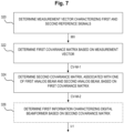
- the instructions when executed by the at least one processor, cause the apparatus 100 to: determine 320 a measurement vector MV characterizing the first and second reference signals RS-1, RS-2 ( Fig. 2 ) based on the first measurement RS-M-1 and the second measurement RS-M-2, determine 322 ( Fig. 7 ) a first covariance matrix CV-M-1 based on the measurement vector MV, determine 324 a second covariance matrix CV-M-2, which is associated with at least one of the first analog beam 1 ( Fig.
- the optional block 326 of Fig. 7 symbolizes an optional determination of the first information I-1 characterizing the digital beamformer DBF based on the second covariance matrix CV-M-2.
- the second covariance matrix CV-M-2 may be determined for any analog beam, e.g., including the first analog beam 1 and the second analog beam 2.
- two consecutive sets of SRS measurements e.g., reference signals RS-1, RS-2 ( Fig. 2 ), observed through different analog beams 1, 2 ( Fig. 5 ) are used to determine the first information I-1 and/or a corresponding digital beamformer as described below.
- y i be an SRS measurement vector after the analog beam i is applied, wherein y i is of size N T X 1 where N T is a number of digital transmit/receive chains ("TRXs") as e.g. used for receiving the SRS.
- TRXs digital transmit/receive chains
- Z SRS be an SRS measurement vector (e.g., at least similar to measurement vector MV of Fig. 7 ), before an analog phase (e.g., phase shift) is applied, wherein Z SRS is of size N T N P X 1 where N P is a number of phase shifters as e.g. used for receiving the SRS.
- w i be a weight matrix corresponding to the analog beam i, wherein w i is of size N T ⁇ N T N P .
- y i w i Z SRS .
- a first aspect may comprise one or more of the following aspects: Determine Z SRS from y i received SRS measurements.
- one measurement of y i may not be sufficient to determine Z SRS because it forms an under-determined system to solve for Z SRS .
- two measurements y i and y k ( i ⁇ k ) e.g., two different measurements
- y i w i Z SRS
- y k w k Z SRS .
- a pseudo-inverse ( w H w ) -1 W H reduces to w -1 .
- a second aspect may comprise one or more of the following aspects:
- a third aspect may comprise one or more of the following aspects:
- R yiyi may be used, e.g., to determine a digital beam (e.g., DIG-B, see Fig. 8 ), which, in some embodiments, may be used, e.g., for exchange of signals, e.g., PDSCH transmission and/or PUSCH reception.
- a digital beam e.g., DIG-B, see Fig. 8
- signals e.g., PDSCH transmission and/or PUSCH reception.
- the digital beam thus determined may be used for PDSCH transmission and/or PUSCH reception, e.g. in between reception of subsequent SRS measurements, and can e.g. be updated, e.g. when SRS measurements are received in a next period, e.g., SRS period.
- At least temporarily storing Z SRS may allow for determination of a digital beamformer independent of a (e.g., currently) best analog beam of a UE 20, thus e.g. alleviating a need to store a covariance matrix for each analog beam, as according to some conventional approaches.
- the principle according to the embodiments may be used for a static channel as well as for a time varying channel, over which the reference signals may be received.
- the channel through which the SRS is exchanged (e.g., transmitted, e.g. by the UE 20 to the gNB 10) does not change across two SRS receptions.
- the first information I-1 and/or Z SRS may be determined accurately, consequently R zz and R yiyi also.
- the instructions when executed by the at least one processor, cause the apparatus 100 to perform at least one of: a) determining 330, based on the first information I-1, a digital beam DIG-B for exchanging 332, for example transmitting and/or receiving, signals, b) exchanging 332, for example transmitting and/or receiving, signals CS using the digital beam DIG-B, c) updating 334 the digital beam DIG-B, e.g. based on further measurements, e.g. SRS measurements, e.g. after a subsequent SRS period, whereby an updated digital beam DIG-B' may be obtained.
- the updated digital beam DIG-B' may be used for exchanging signals, e.g., similar to block 332 of Fig. 8 .
- control signals e.g. control signals according to some accepted standard
- the signals CS that may be exchanged according to block 332 of Fig. 8 may be control signals.
- At least one of a) signals associated with a Physical Downlink Shared Channel, PDSCH, and/or b) signals associated with a Physical Uplink Shared Channel, PUSCH, e.g., according to some accepted standard, may be transmitted and/or received using the digital beam DIG-B (and/or a respective analog beam 1, 2, 3, or 4 ( Fig. 5 )).
- the instructions when executed by the at least one processor, cause the apparatus 100 to: determine 340 an estimate EST-MV of a measurement vector MV based on the first measurement RS-M-1 and the second measurement RS-M-2, determine 342 a first covariance matrix CV-M-1-EST-MV for the estimate EST-MV based on the estimate EST-MV, determine 344 a second covariance matrix CV-M-2-EST-MV related to the estimate, which is associated with one of the first analog beam 1 and the second analog beam 2, based on the first covariance matrix CV-M-1-EST-MV for the estimate.
- this process may e.g. be used when exchanging the reference signals RS-1, RS-2 through a time-varying channel.
- the optional block 346 symbolizes an optional determination of the first information I-1 based on the second covariance matrix CV-M-2-EST-MV.
- the channel through which the SRS is transmitted varies, e.g., from one SRS transmission to subsequent SRS transmission.
- there may be some degree of correlation between the channels of successive SRS transmissions i.e., the underlying Z SRS from the two respective consecutive measurements may have some degree of correlation between them.
- Z SRS,t be an estimated SRS measurement at time t
- Z SRS,t+p be an estimated SRS measurement at time t + p (e.g., at least similar to estimate EST-MV as obtained by block 340 of Fig. 9 ), e.g., before the analog beam is applied.
- Z SRS,t or Z SRS,t+p cannot be directly determined, e.g. observed, because in some embodiments, the associated signals may, e.g. only, be measured/estimated after application of the analog beam weights.
- p may be the SRS transmission period, see, for example, element TD of Fig. 5 .
- y i,t be an SRS measurement after analog beam i is applied at time t
- y k,t + p be an SRS measurement after (another) analog beam k is applied at time t + p .
- ⁇ SRS be the estimate of Z SRS,t+p .
- determine, e.g., compute R ⁇ zz Z ⁇ SRS Z ⁇ SRS H .
- determine, e.g., compute R ⁇ y i y i w i R ⁇ zz w i H , e.g. for at least one, e.g. any, analog beam i .
- the estimate ⁇ SRS may contain an ingrained information of Z SRS,t (e.g., of the previous channel) with beam i and Z SRS,t+p (e.g., of the present channel) with beam k .
- Z SRS,t e.g., of the previous channel
- Z SRS,t+p e.g., of the present channel
- ⁇ SRS one can efficiently determine, e.g. compute, y k,t + p and a corresponding covariance matrix R ⁇ y k y k (e.g., of the present channel).
- R ⁇ yiyi i ⁇ k
- R ⁇ yiyi i ⁇ k
- ⁇ SRS may contain information of Z SRS,t+p with analog beam k , but not with analog beam i .
- the instructions when executed by the at least one processor, cause the apparatus 100 to perform at least one of: a) determining 350 an accuracy ACC-EST-MV of the estimate EST-MV of the measurement vector, e.g., based on a normalized mean square error (NMSE), b) determining 352 an accuracy ACC-2-EST-MV of the second covariance matrix CV-M-2-EST-MV related to the estimate, e.g., based on an NMSE.
- NMSE normalized mean square error
- NMSE normalized mean square error
- RNMSE w k Z ⁇ SRS ⁇ w k Z SRS , t + p w k z SRS , t + p
- RNMSE w k Z ⁇ SRS w k H ⁇ y k , t + p y k , t + p H F y k , t + p y k , t + p H F , where ⁇ represents the L2-norm of a vector and ⁇ F represents the Frobenius norm of a matrix.
- the NMSE may take the norm of the difference in the estimated and actual measurement of y k,t + p and normalizes it with the actual norm of y k,t + p .
- RNMSE may take the Frobenius norm of the difference in the estimated and actual covariance matrix corresponding to y k,t + p and normalizes it with the Frobenius norm of the actual covariance matrix corresponding to y k,t+p .
- Fig. 1B relate to an apparatus 100' for a communication system 1000, the apparatus 100' comprising means 102' for determining 300 ( Fig. 3 ) a first measurement of first reference signals associated with a first analog beam used to receive the first reference signals, determining 302 a second measurement of second reference signals associated with a second analog beam used to receive the second reference signals, determining 304 first information characterizing a digital beamformer based on the first measurement and the second measurement.
- the means 102' for determining the first measurement and the second measurement and for determining the first information may, e.g., comprise at least one processor 102 ( Fig. 1A ), and at least one memory 104 storing instructions 106 that, when executed by the at least one processor 102, cause the apparatus to perform the aforementioned aspects.
- the means 102' for determining the first measurement and the second measurement and for determining the first information may, e.g., comprise circuitry configured to perform one or more of the aforementioned aspects.
- Fig. 2 relate to a network device 10, e.g., base station, e.g., gNB, for a communication system 1000 comprising at least one apparatus 100, 100' according to the embodiments.
- a network device e.g., base station, e.g., gNB
- a communication system 1000 comprising at least one apparatus 100, 100' according to the embodiments.
- Fig. 2 relate to a terminal device 20, e.g., UE, for a communication system 1000 comprising at least one apparatus 100, 100' according to the embodiments.
- a terminal device 20 e.g., UE
- a communication system 1000 comprising at least one apparatus 100, 100' according to the embodiments.
- Fig. 2 relate to a communication system 1000 comprising at least one of: a) an apparatus 100, 100' according to the embodiments, and/or b) a network device 10 according to the embodiments, and/or c) a terminal device 20 according to the embodiments.
- Fig. 3 relate to a method for a communication system 1000, comprising: determining 300 a first measurement of first reference signals associated with a first analog beam used to receive the first reference signals, determining 302 a second measurement of second reference signals associated with a second analog beam used to receive the second reference signals, determining 304 first information characterizing a digital beamformer based on the first measurement and the second measurement.
- the method may comprise one or more further aspects according to the embodiments.
- Fig. 1A relate to a computer program comprising instructions 106 which, when the program is executed by a computer, e.g., comprising the processor 102, cause the computer to carry out at least some aspects of the method according to the embodiments.
- the hybrid beamforming HBF ( Fig. 2 ), which uses a combination of digital beamforming DBF and analog beamforming ABF may enable to reduce cost and/or weight of apparatus 100 and/or a target device 10, 20 for the apparatus. Also, in some embodiments, a complexity and/or power consumption can be reduced by hybrid beamforming HBF, e.g. by reducing a number of RF signal processing chains.
- a hybrid beamforming architecture may be provided which uses digital beamforming in the horizontal direction and analog beamforming in the vertical direction, e.g., because of a larger spread of UEs or users in the horizontal and relatively lower spread of users in the vertical direction.
- a lower spread of users in the vertical direction may imply that a comparatively small number of analog beams in the vertical direction can suffice, e.g., to provide sufficient coverage in the vertical direction.
- hybrid beamforming HBF e.g., instead of digital beamforming, for SRS reception may result in the SRS measurements being "colored" through the lens of the analog beamformer ABF, because of additional phase shifters that may be comprised in the analog beamformer ABF.
- four comparatively narrow analog beams 1, 2, 3, 4 may be provided, e.g., at elevation angles ⁇ -2, -5, -8, -11 ⁇ degrees.
- a channel estimate and the corresponding covariance matrix of at least all four analog beams would have to be determined.
- a digital beamformer for all these analog beams, because in some embodiments, the best analog beam of a UE may keep changing with time based on varying channel conditions.
- UEs may be scheduled on their second or even third or later best analog beam sometimes, e.g., to reduce the latency of waiting until the best beam of the UE is scheduled.
- a digital beamformer is determined by making as many estimations/measurements as there are analog beams, and by using a measurement done on an analog beam to be used for that analog beam alone.
- the principle according to the embodiments enables to determine the digital beamformer (or the respective first information I-1) such that, e.g., instead of making as many estimations/measurements as there are analog beams and using a measurement done on an analog beam to be used for that analog beam alone, in some embodiments, only two, for example (but not necessarily) consecutive, SRS measurements made on any two different analog beams are used.
- these two measurements are enough to select a digital beam for any analog beamformer thus e.g. saving on a number of measurements and avoiding latency and staleness of the estimation.
- the covariance matrix of the channel before the phase shifters can be stored and that may, in some embodiments, be subsequently used to determine the covariance matrix at the digital ports, e.g. digital input. In some embodiments, this applies to static channels as well as to time varying channels.
Landscapes
- Engineering & Computer Science (AREA)
- Signal Processing (AREA)
- Computer Networks & Wireless Communication (AREA)
- Radio Transmission System (AREA)
- Radar Systems Or Details Thereof (AREA)
Applications Claiming Priority (1)
| Application Number | Priority Date | Filing Date | Title |
|---|---|---|---|
| FI20235913 | 2023-08-14 |
Publications (1)
| Publication Number | Publication Date |
|---|---|
| EP4510465A1 true EP4510465A1 (fr) | 2025-02-19 |
Family
ID=92212688
Family Applications (1)
| Application Number | Title | Priority Date | Filing Date |
|---|---|---|---|
| EP24192730.0A Pending EP4510465A1 (fr) | 2023-08-14 | 2024-08-02 | Appareil et procédé pour un système de communication |
Country Status (3)
| Country | Link |
|---|---|
| US (1) | US12250039B1 (fr) |
| EP (1) | EP4510465A1 (fr) |
| CN (1) | CN119496541B (fr) |
Citations (1)
| Publication number | Priority date | Publication date | Assignee | Title |
|---|---|---|---|---|
| US20140355707A1 (en) * | 2013-05-02 | 2014-12-04 | Samsung Electronics Co., Ltd. | Precoder selection method and apparatus for performing hybrid beamforming in wireless communication system |
Family Cites Families (23)
| Publication number | Priority date | Publication date | Assignee | Title |
|---|---|---|---|---|
| US6901122B2 (en) * | 2001-03-27 | 2005-05-31 | Motorola | Method and apparatus for restoring a soft decision component of a signal |
| US8040938B2 (en) * | 2004-03-12 | 2011-10-18 | Telefonaktiebolaget Lm Ericsson (Publ) | Method and apparatus for extended least squares estimation for generalized rake receiver parameters using multiple base stations |
| US7250903B1 (en) * | 2006-04-17 | 2007-07-31 | Rockwell Collins | GPS spoofer and repeater mitigation system using digital spatial nulling |
| US7751463B2 (en) * | 2006-12-05 | 2010-07-06 | Telefonaktiebolaget Lm Ericsson (Publ) | Method and apparatus for suppressing interference based on channelization code power estimation with bias removal |
| KR101839812B1 (ko) * | 2011-08-11 | 2018-03-19 | 삼성전자주식회사 | 혼합 아날로그/디지털 빔포밍을 위한 방법 및 장치 |
| KR20130017572A (ko) * | 2011-08-11 | 2013-02-20 | 삼성전자주식회사 | 하이브리드 빔포밍 시스템에서 아날로그 빔 결정 방법 및 장치 |
| KR20130127347A (ko) * | 2012-05-10 | 2013-11-22 | 삼성전자주식회사 | 아날로그 및 디지털 하이브리드 빔포밍을 통한 통신 방법 및 장치 |
| CN105393482A (zh) * | 2013-10-11 | 2016-03-09 | 华为技术有限公司 | 信道测量和csi反馈的方法、装置和系统 |
| KR101616636B1 (ko) * | 2014-10-16 | 2016-04-28 | 영남대학교 산학협력단 | 듀얼 모드 빔포밍 방법 및 장치 |
| US10031234B1 (en) * | 2015-04-03 | 2018-07-24 | Interstate Electronics Corporation | Global navigation satellite system beam based attitude determination |
| US20170017394A1 (en) * | 2015-07-15 | 2017-01-19 | Futurewei Technologies, Inc. | SYSTEM AND METHOD FOR DATA WAREHOUSE AND FINE GRANULARITY SCHEDULING FOR SYSTEM ON CHIP (SoC) |
| US10200103B2 (en) | 2016-11-23 | 2019-02-05 | Samsung Electronics Co., Ltd. | Method and apparatus to enable multi-resolution CSI reporting in advanced wireless communication systems |
| US10362589B2 (en) | 2017-01-23 | 2019-07-23 | Electronics And Telecommunications Research Institute | Communication method and apparatus using multiple antennas in wireless communication system |
| CN111446996B (zh) * | 2017-04-18 | 2023-06-30 | Oppo广东移动通信有限公司 | 一种用于多天线传输的用户设备、基站中的方法和装置 |
| CN109219062B (zh) * | 2017-06-30 | 2022-04-01 | 中国移动通信有限公司研究院 | 一种波束的确定方法、终端及网络侧设备 |
| US11456790B2 (en) | 2019-08-16 | 2022-09-27 | Qualcomm Incorporated | Multi-beam selection for beamformed multiple input multiple output wireless communications |
| US11012133B2 (en) * | 2019-09-16 | 2021-05-18 | Nokia Solutions And Networks Oy | Efficient data generation for beam pattern optimization |
| US11595919B2 (en) * | 2020-01-31 | 2023-02-28 | Qualcomm Incorporated | SSB channel cancelation |
| US20220094414A1 (en) | 2020-09-18 | 2022-03-24 | Qualcomm Incorporated | Techniques for transformation of analog beamforming codebooks |
| US11588528B2 (en) * | 2020-12-08 | 2023-02-21 | MMRFIC Technology Pvt. Ltd. | Optimal hybrid beamformer in a multi antenna wireless systems |
| US20220278717A1 (en) * | 2021-03-01 | 2022-09-01 | At&T Intellectual Property I, L.P. | Method and system for artificial intelligence (ai)-based monitoring and controlling of network parameters |
| US12562803B2 (en) * | 2021-12-23 | 2026-02-24 | Intel Corporation | Methods and devices for beam management operation |
| WO2024049689A1 (fr) * | 2022-09-02 | 2024-03-07 | Apple Inc. | Technologies de gestion des faisceaux utilisant une architecture hybride de formation de faisceaux |
-
2024
- 2024-08-02 EP EP24192730.0A patent/EP4510465A1/fr active Pending
- 2024-08-13 CN CN202411109674.5A patent/CN119496541B/zh active Active
- 2024-08-13 US US18/802,443 patent/US12250039B1/en active Active
Patent Citations (1)
| Publication number | Priority date | Publication date | Assignee | Title |
|---|---|---|---|---|
| US20140355707A1 (en) * | 2013-05-02 | 2014-12-04 | Samsung Electronics Co., Ltd. | Precoder selection method and apparatus for performing hybrid beamforming in wireless communication system |
Also Published As
| Publication number | Publication date |
|---|---|
| US20250062807A1 (en) | 2025-02-20 |
| CN119496541B (zh) | 2026-01-23 |
| CN119496541A (zh) | 2025-02-21 |
| US12250039B1 (en) | 2025-03-11 |
Similar Documents
| Publication | Publication Date | Title |
|---|---|---|
| US10734722B2 (en) | Beamforming method, apparatus for polarized antenna array and radio communication device and system thereof | |
| CN114424623B (zh) | 基于机器学习的信道估计 | |
| US9537587B2 (en) | Efficient large-scale multiple input multiple output communications | |
| US11128342B2 (en) | Method and apparatus for determining the angle of departure | |
| EP3979669A1 (fr) | Procédé et appareil de rétroaction d'informations, procédé et appareil de réception d'informations, procédé et appareil d'acquisition d'informations, noeud de communication et support de stockage | |
| US20240196361A1 (en) | Method of positioning a node in a cellular network | |
| EP2992620B1 (fr) | Procédé et appareil de mesure et de rétroaction d'informations de canal dans un système de communication au moyen de formation de faisceau | |
| CN103138817B (zh) | 一种用于选择上行链路传输天线的方法与设备 | |
| US10425855B2 (en) | Methods for acquiring and feeding back channel state information, base station and terminal | |
| JP4976504B2 (ja) | 移動体無線通信システムにおける送信効率を向上させるための方法及び装置 | |
| US10291308B2 (en) | Channel state information feedback method, device and system | |
| US20170272223A1 (en) | Method for determining weight for beamforming in wireless communication system and apparatus therefor | |
| EP2238695B1 (fr) | Procédé de communication d'un signal à l'aide d'une orientation de faisceau analogique, station d'émission et station de réception associés | |
| CN116348778A (zh) | 用于具有动态背景信息的预编码信号的定位增强 | |
| TWI635737B (zh) | 一種導頻信號的發送、接收處理方法及裝置 | |
| US20210396832A1 (en) | Method and Apparatus for Determining the Angle of Departure | |
| US20210067226A1 (en) | Uplink beam management | |
| CN106411457A (zh) | 信道状态信息获取方法、反馈方法、基站及终端 | |
| EP4243299A1 (fr) | Dispositif de communication sans fil transmettant et recevant des données à l'aide d'une rétroaction d'informations d'état de canal et son procédé de fonctionnement | |
| CN106033990B (zh) | 一种信道状态信息反馈方法、获取方法及装置 | |
| EP4510465A1 (fr) | Appareil et procédé pour un système de communication | |
| EP2517376B1 (fr) | Procédé de suppression d'une interférence dans des directions opposées | |
| US10090893B2 (en) | Frequency division multiple antenna distribution | |
| JP2019530359A (ja) | チャネル状態測定方法、送信方法、移動局及び基地局 | |
| EP4057528A1 (fr) | Procédé de calcul de l'affaiblissement de propagation et appareil de commande de puissance |
Legal Events
| Date | Code | Title | Description |
|---|---|---|---|
| PUAI | Public reference made under article 153(3) epc to a published international application that has entered the european phase |
Free format text: ORIGINAL CODE: 0009012 |
|
| STAA | Information on the status of an ep patent application or granted ep patent |
Free format text: STATUS: THE APPLICATION HAS BEEN PUBLISHED |
|
| AK | Designated contracting states |
Kind code of ref document: A1 Designated state(s): AL AT BE BG CH CY CZ DE DK EE ES FI FR GB GR HR HU IE IS IT LI LT LU LV MC ME MK MT NL NO PL PT RO RS SE SI SK SM TR |
|
| STAA | Information on the status of an ep patent application or granted ep patent |
Free format text: STATUS: REQUEST FOR EXAMINATION WAS MADE |
|
| 17P | Request for examination filed |
Effective date: 20250819 |