EP4510722A1 - Verfahren und vorrichtung zur konfiguration eines uplink-positionierungsreferenzsignals sowie vorrichtung und speichermedium - Google Patents
Verfahren und vorrichtung zur konfiguration eines uplink-positionierungsreferenzsignals sowie vorrichtung und speichermedium Download PDFInfo
- Publication number
- EP4510722A1 EP4510722A1 EP22936965.7A EP22936965A EP4510722A1 EP 4510722 A1 EP4510722 A1 EP 4510722A1 EP 22936965 A EP22936965 A EP 22936965A EP 4510722 A1 EP4510722 A1 EP 4510722A1
- Authority
- EP
- European Patent Office
- Prior art keywords
- reference signal
- positioning reference
- terminal
- uplink positioning
- network device
- Prior art date
- Legal status (The legal status is an assumption and is not a legal conclusion. Google has not performed a legal analysis and makes no representation as to the accuracy of the status listed.)
- Pending
Links
Images
Classifications
-
- H—ELECTRICITY
- H04—ELECTRIC COMMUNICATION TECHNIQUE
- H04L—TRANSMISSION OF DIGITAL INFORMATION, e.g. TELEGRAPHIC COMMUNICATION
- H04L5/00—Arrangements affording multiple use of the transmission path
- H04L5/003—Arrangements for allocating sub-channels of the transmission path
- H04L5/0048—Allocation of pilot signals, i.e. of signals known to the receiver
-
- H—ELECTRICITY
- H04—ELECTRIC COMMUNICATION TECHNIQUE
- H04W—WIRELESS COMMUNICATION NETWORKS
- H04W64/00—Locating users or terminals or network equipment for network management purposes, e.g. mobility management
-
- H—ELECTRICITY
- H04—ELECTRIC COMMUNICATION TECHNIQUE
- H04L—TRANSMISSION OF DIGITAL INFORMATION, e.g. TELEGRAPHIC COMMUNICATION
- H04L5/00—Arrangements affording multiple use of the transmission path
-
- H—ELECTRICITY
- H04—ELECTRIC COMMUNICATION TECHNIQUE
- H04L—TRANSMISSION OF DIGITAL INFORMATION, e.g. TELEGRAPHIC COMMUNICATION
- H04L5/00—Arrangements affording multiple use of the transmission path
- H04L5/003—Arrangements for allocating sub-channels of the transmission path
- H04L5/0048—Allocation of pilot signals, i.e. of signals known to the receiver
- H04L5/0051—Allocation of pilot signals, i.e. of signals known to the receiver of dedicated pilots, i.e. pilots destined for a single user or terminal
Definitions
- This application relates to the field of mobile communications and, in particular, to a method and apparatus for configuring a reference signal, a device and a storage medium.
- the 5th Generation Mobile Communication Technology (5G) New Radio (NR) introduces a variety of positioning technologies to realize the positioning of terminals.
- the network device For the uplink positioning technology and the uplink and downlink hybrid positioning technology, it is necessary for the network device to configure an uplink positioning reference signal for the terminal so that the terminal sends the uplink positioning reference signal to the network device according to an uplink positioning reference signal configuration to realize the positioning of the terminal.
- Embodiments of the present application provide a method and apparatus for configuring an uplink positioning reference signal, a device and a storage medium.
- the described technical solutions are as follows.
- a terminal for configuring an uplink positioning reference signal.
- the method is performed by a terminal and includes:
- a network device includes:
- a method for configuring an uplink positioning reference signal is performed by an LMF network element and includes:
- an apparatus for configuring an uplink positioning reference signal including:
- an apparatus for configuring an uplink positioning reference signal including:
- an apparatus for configuring an uplink positioning reference signal including:
- a terminal including: a processor, a transceiver connected to the processor, and a memory for storing instructions executable by the processor, where the processor is configured to load and execute the instructions to implement the method for configuring the uplink positioning reference signal as described in the above aspects.
- a network device including: a processor, a transceiver connected to the processor, and a memory for storing instructions executable by the processor, where the processor is configured to load and execute the instructions to implement the method for configuring the uplink positioning reference signal as described in the above aspects.
- a computer-readable storage medium storing executable instructions which, when loaded and executed by a processor, cause the processor to implement the method for configuring the uplink positioning reference signal as described in the above aspects.
- a chip including a programmable logic circuit and/or program instructions which, when the chip is running on a computer, are configured to implement the method for configuring the uplink positioning reference signal as described in the above aspects.
- a computer program product or computer program including computer instructions stored in a computer-readable storage medium.
- a processor reads and executes the computer instructions from the computer-readable storage medium, causing the computer device performs the method for configuring the uplink positioning reference signal as described in the above aspects.
- the technical solutions provided by the present application include at least the following beneficial effects: By actively requesting the configuration of the uplink positioning reference signal from the network device and/or the LMF network element by the terminal, it is possible to instantly configure the uplink positioning reference signal for the terminal according to the terminal's request when the terminal releases the stored uplink positioning reference signal configuration. This can reduce the delay in configuring the uplink positioning reference signal for the terminal, thereby reducing the positioning delay and improving the flexibility of configuring the uplink positioning reference signal.
- first, second, third, etc. may be employed in the present disclosure to describe various types of information, such information should not be limited by these terms. These terms are only used to distinguish the same type of information from one another.
- first information may also be referred to as second information, and similarly, second information may be referred to as first information.
- phrase “if” as used herein may be interpreted as "at the time of... “ or “when... “ or “in response to determining".
- the 5th Generation Mobile Communication Technology (5G) New Radio (NR) introduces a variety of positioning technologies to realize the positioning of terminals.
- the uplink positioning reference signal is a Sounding Reference Signal (SRS).
- SRS Sounding Reference Signal
- the network device needs to first configure the uplink positioning reference signal for the terminal before the uplink positioning reference signal sent by the terminal can be received by the network device.
- the network device can realize configuring the uplink positioning reference signal for the terminal by sending an uplink positioning reference signal configuration to the terminal.
- the uplink positioning reference signal configuration includes time-frequency resources used by the terminal when sending the uplink positioning reference signal.
- an uplink positioning reference signal needs to be used.
- R16 when positioning the terminal using the above methods, the terminal needs to be in a Radio Resource Control (RRC) connected state, which may lead to a high power consumption overhead of the terminal.
- RRC Radio Resource Control
- the positioning of the terminal in an RRC inactive state is supported.
- the terminal while in the RRC inactive state, can send an uplink positioning reference signal to the network device.
- the network device will configure the uplink positioning reference signal for the terminal via an RRC release message when it transitions the terminal from the RRC connected state to the RRC inactive state.
- the detailed configuration corresponding to the uplink positioning reference signal is included in 'srs-PosRRC-InactiveConfig' of the RRC release message, and the terminal needs to release the uplink positioning reference signal configured for it by the network device if the terminal has performed cell reselection, i.e., to release the uplink positioning reference signal configuration. For example, after performing cell reselection, the terminal will delete the uplink positioning reference signal configuration stored locally.
- a Location Management Function (LMF) network element sends a request message to a base station through a New Radio Positioning Protocol A (NRPPa) message to request the base station to configure the uplink positioning reference signal for the terminal.
- the base station will determine an uplink positioning reference signal configuration and send the determined uplink positioning reference signal configuration to the terminal via an RRC message, thereby realizing the configuration of the uplink positioning reference signal for the terminal.
- the base station will also send the uplink positioning reference signal configuration, which is sent to the terminal, to the LMF network element.
- the uplink positioning reference signal configured by the base station for the terminal When cell reselection occurs at a terminal in an RRC inactive state, the uplink positioning reference signal configured by the base station for the terminal will be released, so it is necessary to reconfigure the uplink positioning reference signal for the terminal.
- the configuration of the uplink positioning reference signal for the terminal is realized by the above scheme, that is, the LMF network element requests the base station to configure the uplink positioning reference signal for the terminal.
- the LMF network element does not know that the terminal has released the uplink positioning reference signal configuration due to the occurrence of cell reselection, and thus the LMF network element cannot instantly request the base station to configure the uplink positioning reference signal for the terminal again after the terminal releases the stored uplink positioning reference signal configuration. Therefore, the delay in configuring the uplink positioning reference signal for the terminal will be increased, thereby increasing the positioning delay.
- the method provided by embodiments of the present application by having the terminal actively request the network device and/or the LMF network element to configure an uplink positioning reference signal, is able to realize that when the terminal releases the stored uplink positioning reference signal configuration, the uplink positioning reference signal is instantaneously configured for the terminal according to the request of the terminal, thereby being able to reduce the delay in configuring the uplink positioning reference signal for the terminal, which in turn reduces the positioning delay and improves the flexibility of configuring the uplink positioning reference signal.
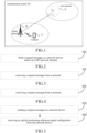
- FIG. 1 illustrates a schematic diagram of system architecture of a communication system provided by an embodiment of the present application.
- the system architecture may include a terminal 10, an access network device 20, and a core network device 30.
- the terminal 10 may refer to a User Equipment (UE), an access terminal device, a subscriber unit, a subscriber station, a mobile site, a mobile station, a remote station, a remote terminal device, a mobile device, a wireless communication device, a user agent, or a subscriber device.
- UE User Equipment
- the terminal may also be a cellular telephone, a cordless telephone, a Session Initiation Protocol (SIP) telephone, a Wireless Local Loop (WLL) station, a Personal Digital Assistant (PDA), a handheld device with wireless communication functions, a computing device or other processing device connected to a wireless modem, an in-vehicle device, a wearable device, a terminal device in a 5th Generation System (5GS) or in a future evolved Public Land Mobile Network (PLMN), etc., which is not limited by the embodiments of the present application.
- the devices mentioned above are collectively referred to as terminals. There are usually multiple terminals 10, and one or more terminals 10 can be distributed in a cell managed by each access network device 20.
- the access network device 20 is a device deployed in an access network and configured to provide wireless communication functions for the terminal 10.
- the access network device 20 may include various forms of macro base stations, micro base stations, relay stations, access points, and the like.
- the name of the device having the function of an access network device may be different.
- a gNodeB or a gNB In systems using different wireless access technologies, the name of the "access network device" may change as the communication technology evolves.
- access network devices For convenience of description, in the embodiments of the present application, the above-described devices that provide wireless communication functions for the terminal 10 are collectively referred to as access network devices.
- a communication relationship may be established between the terminal 10 and the core network device 30.
- the access network device 20 may be an Evolved Universal Terrestrial Radio Access Network (EUTRAN) or one or more eNodeBs the EUTRAN; in a 5G NR system, the access network device 20 may be a RAN or one or more gNBs in the RAN.
- EUTRAN Evolved Universal Terrestrial Radio Access Network
- eNodeB the EUTRAN
- 5G NR the access network device 20 may be a RAN or one or more gNBs in the RAN.
- the functions of the core network device 30 are mainly to provide user connectivity, manage users, and complete bearer for services, and serve as an interface from the bearer network to the external network.
- the core network device in the 5G NR system may include an Access and Mobility Management Function (AMF) entity, a User Plane Function (UPF) entity, a Session Management Function (SMF) entity, and a Location Management Function (LMF) entity, etc.
- AMF Access and Mobility Management Function
- UPF User Plane Function
- SMF Session Management Function
- LMF Location Management Function
- the access network device 20 and the core network device 30 may be collectively referred to as network devices.
- the core network device 30 is illustrated as an example of an LMF network element.
- the access network device 20 and the core network device 30 communicate with each other through a certain air interface technology, such as an NG interface in a 5G NR system.
- the access network device 20 and the terminal 10 communicate with each other through a certain air interface technology, such as a Uu interface.
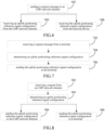
- FIG. 2 illustrates a flowchart of a method for configuring an uplink positioning reference signal provided by an embodiment of the present application.
- the method can be applied in the terminal shown in FIG. 1 .
- the method includes the following step.
- Step 202 sending a request message to a network device and/or an LMF network element.
- the request message is used to request the network device and/or the LMF network element to configure an uplink positioning reference signal for the terminal.
- configuring the uplink positioning reference signal for the terminal means sending to the terminal an uplink positioning reference signal configuration which is used for the terminal to send the uplink positioning reference signal.
- the uplink positioning reference signal configuration includes time-frequency resources to be used by the terminal for sending the uplink positioning reference signal.
- the request message also carries a reason for the terminal to request the uplink positioning reference signal.
- the terminal will send the above-described request message to the network device and/or the LMF network element if at least one of the following conditions is satisfied:
- the above conditions include at least one of the following conditions:
- the uplink positioning reference signal stored by the terminal has become invalid, which means that, currently, the uplink positioning reference that has been configured for the terminal is invalid.
- the uplink positioning reference signal stored by the terminal has become invalid, which can be regarded as the uplink positioning reference signal configuration stored by the terminal has become invalid, e.g., the terminal releases its stored uplink positioning reference signal configuration.
- cell reselection has occurred at the terminal, causing the terminal to release the stored uplink positioning reference signal configuration.
- the terminal releasing the stored uplink positioning reference signal configuration means that the terminal deletes the stored uplink positioning reference signal configuration from the local storage.
- the network device will respond to the request message, determine an uplink positioning reference signal configuration for the terminal and send it to the terminal, thereby realizing the configuration of the uplink positioning reference signal for the terminal.
- the network device will also send its determined uplink positioning reference signal configuration to the LMF network element.
- the network device belongs to a serving cell of the terminal.
- the LMF network element will respond to the request message and request the network device to configure the uplink positioning reference signal for the terminal.
- the network device will respond to the request from the LMF network element, determine the uplink positioning reference signal configuration for the terminal, and send it to the LMF network element, after which the LMF network element will send the uplink positioning reference signal configuration determined by the network device to the terminal, thereby realizing the configuration of the uplink positioning reference signal for the terminal.
- the network device can also respond to the request from the LMF network element, determine the uplink positioning reference signal configuration for the terminal and send it directly to the terminal.
- the network device will also send the determined uplink positioning reference signal configuration to the LMF network element.
- the network device described above belongs to a serving cell of the terminal.
- the method provided in this embodiment by having the terminal actively request the network device and/or the LMF network element to configure the uplink positioning reference signal, is able to realize that when the terminal releases the stored uplink positioning reference signal configuration, the uplink positioning reference signal is instantaneously configured for the terminal according to the request of the terminal, thereby being able to reduce the delay in configuring the uplink positioning reference signal for the terminal, which in turn reduces the positioning delay and improves the flexibility of configuring the uplink positioning reference signal.
- FIG. 3 illustrates a flowchart of a method for configuring an uplink positioning reference signal provided by an embodiment of the present application.
- the method can be applied in the access network device shown in FIG. 1 .
- the method includes the following step.
- Step 302 receiving a request message from a terminal.
- the request message is used to request the network device to configure an uplink positioning reference signal for the terminal.
- configuring the uplink positioning reference signal for the terminal means sending to the terminal an uplink positioning reference signal configuration which is used for the terminal to send the uplink positioning reference signal.
- the uplink positioning reference signal configuration includes time-frequency resources to be used by the terminal for sending the uplink positioning reference signal.
- the request message also carries a reason for the terminal to request the uplink positioning reference signal.
- the network device will respond to the request message, determine an uplink positioning reference signal configuration for the terminal and send it to the terminal, thereby realizing the configuration of the uplink positioning reference signal for the terminal.
- the network device will also send its determined uplink positioning reference signal configuration to the LMF network element.
- the network device belongs to a serving cell of the terminal.
- the method provided in this embodiment by having the terminal actively request the network device to configure the uplink positioning reference signal, is able to realize that when the terminal releases the stored uplink positioning reference signal configuration, the uplink positioning reference signal is instantaneously configured for the terminal according to the request of the terminal, thereby being able to reduce the delay in configuring the uplink positioning reference signal for the terminal, which in turn reduces the positioning delay and improves the flexibility of configuring the uplink positioning reference signal.
- FIG. 4 illustrates a flowchart of a method for configuring an uplink positioning reference signal provided by an embodiment of the present application.
- the method can be applied in the core network device shown in FIG. 1 .
- the method includes the following step.
- Step 402 receiving a request message from a terminal.
- the request message is used to request the LMF network element to configure an uplink positioning reference signal for the terminal.
- configuring the uplink positioning reference signal for the terminal means sending to the terminal an uplink positioning reference signal configuration which is used for the terminal to send the uplink positioning reference signal.
- the uplink positioning reference signal configuration includes time-frequency resources to be used by the terminal for sending the uplink positioning reference signal.
- the request message also carries a reason for the terminal to request the uplink positioning reference signal.
- the LMF network element will respond to the request message and request the network device to configure the uplink positioning reference signal for the terminal.
- the network device will respond to the request from the LMF network element, determine an uplink positioning reference signal configuration for the terminal, and send it to the LMF network element, after which the LMF network element will send the uplink positioning reference signal configuration determined by the network device to the terminal, thereby realizing the configuration of the uplink positioning reference signal for the terminal.
- the network device can also respond to the request from the LMF network element, determine the uplink positioning reference signal configuration for the terminal and send it directly to the terminal.
- the network device will also send the determined uplink positioning reference signal configuration to the LMF network element.
- the network device described above belongs to a serving cell of the terminal.
- the method provided in this embodiment by having the terminal actively request the LMF network element to configure the uplink positioning reference signal, is able to realize that when the terminal releases the stored uplink positioning reference signal configuration, the uplink positioning reference signal is instantaneously configured for the terminal according to the request of the terminal, thereby being able to reduce the delay in configuring the uplink positioning reference signal for the terminal, which in turn reduces the positioning delay and improves the flexibility of configuring the uplink positioning reference signal.
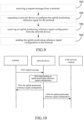
- FIG. 5 illustrates a flowchart of a method for configuring an uplink positioning reference signal provided by an embodiment of the present application.
- the method can be applied in the terminal shown in FIG. 1 .
- the method includes the following steps.
- Step 502 sending a request message to a network device.
- the request message is used to request the network device to configure an uplink positioning reference signal for the terminal.
- configuring the uplink positioning reference signal for the terminal means sending to the terminal an uplink positioning reference signal configuration which is used for the terminal to send the uplink positioning reference signal.
- the uplink positioning reference signal configuration includes time-frequency resources to be used by the terminal for sending the uplink positioning reference signal.
- the request message also carries a reason for the terminal to request the uplink positioning reference signal.
- the reason for the terminal to request the uplink positioning reference signal includes at least one of the following:
- the terminal will send the above-described request message to the network device if at least one of the following conditions is satisfied:
- the above conditions include at least one of the following conditions:
- the uplink positioning reference signal stored by the terminal has become invalid, which means that, currently, the uplink positioning reference that has been configured for the terminal is invalid.
- the uplink positioning reference signal stored by the terminal has become invalid, which can be regarded as the uplink positioning reference signal configuration stored by the terminal has become invalid, e.g., the terminal releases its stored uplink positioning reference signal configuration.
- cell reselection has occurred at the terminal, causing the terminal to release the stored uplink positioning reference signal configuration.
- the terminal releasing the stored uplink positioning reference signal configuration means that the terminal deletes the stored uplink positioning reference signal configuration from the local storage.
- the uplink positioning reference signal stored by the terminal, that has been activated is a semi-persistent uplink positioning reference signal, or a non-periodic uplink positioning reference signal.
- the request message sent by the terminal to the network device is carried in an RRC resume request message.
- Step 504 receiving an uplink positioning reference signal configuration from the network device.
- the uplink positioning reference signal configuration is determined by the network device in response to the request message from the terminal.
- the network device will respond to the request message, and determine an uplink positioning reference signal configuration for the terminal and send it to the terminal, thereby realizing the configuration of the uplink positioning reference signal for the terminal.
- the network device will also send the determined uplink positioning reference signal configuration to the LMF network element.
- the network device belongs to a serving cell of the terminal.
- the uplink positioning reference signal configuration sent by the network device to the terminal is carried in an RRC message.
- the RRC message includes at least one of: an RRC release message, an RRC reconfiguration message, or an RRC setup message.
- the uplink positioning reference signal configuration sent by the network device to the LMF network element is carried in an NRPPa message.
- the NRPPa message includes at least one of a terminal-associated NRPPa (UE association NRPPa) message and a non-terminal-associated NRPPa (non-UE association NRPPa) message.
- the method provided in this embodiment by having the terminal actively request the network device to configure the uplink positioning reference signal, is able to realize that when the terminal releases the stored uplink positioning reference signal configuration, the uplink positioning reference signal is instantaneously configured for the terminal according to the request of the terminal, thereby being able to reduce the delay in configuring the uplink positioning reference signal for the terminal, which in turn reduces the positioning delay and improves the flexibility of configuring the uplink positioning reference signal.
- FIG. 6 illustrates a flowchart of a method for configuring an uplink positioning reference signal provided by an embodiment of the present application.
- the method can be applied in the terminal shown in FIG. 1 .
- the method includes the following steps.
- Step 602 sending a request message to an LMF network element.
- the request message is used to request the network device to configure an uplink positioning reference signal for the terminal.
- configuring the uplink positioning reference signal for the terminal means sending to the terminal an uplink positioning reference signal configuration which is used for the terminal to send the uplink positioning reference signal.
- the uplink positioning reference signal configuration includes time-frequency resources to be used by the terminal for sending the uplink positioning reference signal.
- the request message further carries a reason for the terminal to request the uplink positioning reference signal.
- the reason for the terminal to request the uplink positioning reference signal includes at least one of the following:
- the terminal will send the above-described request message to the LMF network element if at least one of the following conditions is satisfied:
- the above conditions include at least one of the following conditions:
- the uplink positioning reference signal stored by the terminal has become invalid, which means that, currently, the uplink positioning reference that has been configured for the terminal is invalid.
- the uplink positioning reference signal stored by the terminal has become invalid, which can be regarded as the uplink positioning reference signal configuration stored by the terminal has become invalid, e.g., the terminal releases its stored uplink positioning reference signal configuration.
- cell reselection has occurred at the terminal, causing the terminal to release the stored uplink positioning reference signal configuration.
- the terminal releasing the stored uplink positioning reference signal configuration means that the terminal deletes the stored uplink positioning reference signal configuration from the local storage.
- the uplink positioning reference signal stored by the terminal, that has been activated is a semi-persistent uplink positioning reference signal, or a non-periodic uplink positioning reference signal.
- the terminal sends the request message to the LMF network element in at least two ways as follows.
- the terminal sends the request message to the LMF network element via the network device based on an RRC message, such as an RRC resume request message, i.e., the network device transparently transmits the request message sent by the terminal to the LMF network element.
- RRC resume request message carries uplink delivery information (i.e., a UL Information Transfer message), and the uplink delivery information carries the request message.
- the network device after receiving the above information sent by the terminal, will send the uplink delivery information to the LMF network element.
- the uplink delivery information refers to an Uplink Non-Access Stratum Transport (i.e., Uplink NAS Transport) message.
- the network device that transparently transmits the request message of the terminal may belong or may not belong to a serving cell of the terminal.
- LPP LTE Positioning Protocol
- the terminal can also send the request message to the LMF network element in other ways, and the above implementations are used as examples only and are not to be taken as a limitation of the solutions provided by the embodiments of the present application.
- Step 604 receiving an uplink positioning reference signal configuration from the LMF network element.
- the LMF network element will respond to the request message and request the network device to configure the uplink positioning reference signal for the terminal.
- the network device will respond to the request of the LMF network element, determine an uplink positioning reference signal configuration for the terminal, and send it to the LMF network element, after which the LMF network element will send the uplink positioning reference signal configuration determined by the network device to the terminal, thereby realizing the configuration of the uplink positioning reference signal for the terminal.
- the network device described above belongs to a serving cell of the terminal.
- the uplink positioning reference signal configuration sent by the LMF network element to the terminal is carried in the LPP message.
- the LMF network element requests the network device to configure the uplink positioning reference signal to the terminal via the NRPPa message.
- the network device sends its determined uplink positioning reference signal configuration to the LMF network element via the NRPPa message.
- the NRPPa message includes at least one of a UE association NRPPa message or a non-UE association NRPPa message.
- Step 606 receiving the uplink positioning reference signal configuration from the network device.
- the LMF network element will respond to the request message and request the network device to configure the uplink positioning reference signal for the terminal.
- the network device will respond to the request of the LMF network element, determine the uplink positioning reference signal configuration for the terminal, and send it directly to the terminal, thereby realizing the configuration of the uplink positioning reference signal for the terminal.
- the network device will also send its determined uplink positioning reference signal configuration to the LMF network element.
- the network device described above belongs to a serving cell of the terminal.
- the LMF network element requests the network device to configure the uplink positioning reference signal for the terminal via the NRPPa message.
- the network device sends its determined uplink positioning reference signal configuration to the LMF network element via the NRPPa message.
- the NRPPa message includes at least one of a UE association NRPPa message or a non-UE association NRPPa message.
- the uplink positioning reference signal configuration sent by the network device to the terminal is carried in an RRC message.
- the RRC message includes at least one of an RRC release message, an RRC reconfiguration message, or an RRC setup message.
- step 604 as well as step 606 are parallel schemes. That is, the terminal, in the case of requesting the LMF network element to configure the uplink positioning reference signal configuration for it, will receive the uplink positioning reference signal configuration sent to it by the LMF network element, or receive the uplink positioning reference signal configuration sent to it by the network device.
- the method provided in this embodiment by having the terminal actively request the LMF network element to configure the uplink positioning reference signal, is able to realize that when the terminal releases the stored uplink positioning reference signal configuration, the uplink positioning reference signal is instantaneously configured for the terminal according to the request of the terminal, thereby being able to reduce the delay in configuring the uplink positioning reference signal for the terminal, which in turn reduces the positioning delay and improves the flexibility of configuring the uplink positioning reference signal.
- FIG. 7 illustrates a flowchart of a method for configuring an uplink positioning reference signal provided by an embodiment of the present application.
- the method can be applied in the access network device shown in FIG. 1 .
- the method includes the following steps.
- Step 702 receiving a request message from a terminal.
- the request message is used to request the network device to configure an uplink positioning reference signal for the terminal.
- configuring the uplink positioning reference signal for the terminal means sending to the terminal an uplink positioning reference signal configuration which is used for the terminal to send the uplink positioning reference signal.
- the uplink positioning reference signal configuration includes time-frequency resources to be used by the terminal for sending the uplink positioning reference signal.
- the request message sent by the terminal to the network device is carried in an RRC resume request message.
- Step 704 determining an uplink positioning reference signal configuration.
- the uplink positioning reference signal configuration is determined by the network device in response to the request message from the terminal.
- the network device will respond to the request message and determine the uplink positioning reference signal configuration for the terminal.
- the network device belongs to a serving cell of the terminal.
- Step 706 sending the uplink positioning reference signal configuration to the terminal.
- the network device After the network device determines the uplink positioning reference signal configuration for the terminal, it will send its determined uplink positioning reference signal configuration to the terminal, thereby realizing the configuration of the uplink positioning reference signal for the terminal. Optionally, the network device will also send its determined uplink positioning reference signal configuration to the LMF network element.
- the uplink positioning reference signal configuration sent by the network device to the terminal is carried in an RRC message.
- the RRC message includes at least one of an RRC release message, an RRC reconfiguration message, or an RRC setup message.
- the uplink positioning reference signal configuration sent by the network device to the LMF network element is carried in an NRPPa message.
- the NRPPa message includes at least one of a UE association NRPPa message or a non-UE association NRPPa message.
- the method provided in this embodiment by having the terminal actively request the network device to configure the uplink positioning reference signal, is able to realize that when the terminal releases the stored uplink positioning reference signal configuration, the uplink positioning reference signal is instantaneously configured for the terminal according to the request of the terminal, thereby being able to reduce the delay in configuring the uplink positioning reference signal for the terminal, which in turn reduces the positioning delay and improves the flexibility of configuring the uplink positioning reference signal.
- FIG. 8 illustrates a flowchart of a method for configuring an uplink positioning reference signal provided by an embodiment of the present application.
- the method can be applied in the access network device shown in FIG. 1 .
- the method includes the following steps.
- Step 802 receiving a request from an LMF network element.
- the request is used to request the network device to configure an uplink positioning reference signal for the terminal, which is sent by the LMF network element in the case where it has received a request message from the terminal.
- the request message is used to request the LMF network element to configure an uplink positioning reference signal for the terminal.
- configuring the uplink positioning reference signal for the terminal means sending to the terminal an uplink positioning reference signal configuration which is used for the terminal to send the uplink positioning reference signal.
- the uplink positioning reference signal configuration includes time-frequency resources to be used by the terminal for sending the uplink positioning reference signal.
- the LMF network element requests the network device to configure an uplink positioning reference signal for the terminal via an NRPPa message.
- the NRPPa message includes at least one of a UE association NRPPa message or a non-UE association NRPPa message.
- Step 804 determining an uplink positioning reference signal configuration.
- This uplink positioning reference signal configuration is determined by the network device in response to a request from the LMF network element.
- the LMF network element requests the network device to configure the uplink positioning reference signal for the terminal
- the network device will respond to the request and determine the uplink positioning reference signal configuration for the terminal.
- the network device belongs to a serving cell of the terminal.
- Step 806 sending the uplink positioning reference signal configuration to the LMF network element.
- the network device After determining the uplink positioning reference signal configuration for the terminal, the network device will send its determined uplink positioning reference signal configuration to the LMF network element, after which the LMF network element will send the uplink positioning reference signal configuration determined by the network device to the terminal, thereby realizing the configuration of the uplink positioning reference signal for the terminal.
- the network device sends its determined uplink positioning reference signal configuration to the LMF network element via an NRPPa message.
- the NRPPa message includes at least one of a UE association NRPPa message or a non-UE association NRPPa message.
- the uplink positioning reference signal configuration sent by the LMF network element to the terminal is carried in a LPP message.
- Step 808 sending the uplink positioning reference signal configuration to the terminal.
- the network device After determining the uplink positioning reference signal configuration for the terminal, the network device will send its determined uplink positioning reference signal configuration directly to the terminal, thereby realizing the configuration of the uplink positioning reference signal for the terminal. Optionally, the network device will also send its determined uplink positioning reference signal configuration to the LMF network element.
- the uplink positioning reference signal configuration sent by the network device to the terminal is carried in an RRC message.
- the RRC message includes at least one of an RRC release message, an RRC reconfiguration message, or an RRC setup message.
- the network device sends its determined uplink positioning reference signal configuration to the LMF network element via an NRPPa message.
- the NRPPa message includes at least one of a UE association NRPPa message or a non-UE association NRPPa message.
- step 806 in the case of configuring an uplink positioning reference signal for the terminal based on a request from the LMF network element, will send its determined uplink positioning reference signal configuration to the LMF network element, and the LMF network element will send the uplink positioning reference signal configuration to the terminal.
- the network device will send its determined uplink positioning reference signal configuration directly to the terminal.
- the method provided in this embodiment by having the terminal actively request the LMF network element to configure the uplink positioning reference signal, is able to realize that when the terminal releases the stored uplink positioning reference signal configuration, the uplink positioning reference signal is instantaneously configured for the terminal according to the request of the terminal, thereby being able to reduce the delay in configuring the uplink positioning reference signal for the terminal, which in turn reduces the positioning delay and improves the flexibility of configuring the uplink positioning reference signal.
- FIG. 9 illustrates a flowchart of a method for configuring an uplink positioning reference signal provided by an embodiment of the present application.
- the method can be applied in the terminal shown in FIG. 1 .
- the method includes the following steps.
- Step 902 receiving a request message from a terminal.
- the request message is used to request the LMF network element to configure an uplink positioning reference signal for the terminal.
- configuring the uplink positioning reference signal for the terminal means sending to the terminal an uplink positioning reference signal configuration which is used for the terminal to send the uplink positioning reference signal.
- the uplink positioning reference signal configuration includes time-frequency resources to be used by the terminal for sending the uplink positioning reference signal.
- the request message further carries a reason for the terminal to request the uplink positioning reference signal.
- the reason for the terminal to request the uplink positioning reference signal includes at least one of the following:
- the LMF network element receives the request message sent by the terminal in at least two ways as follows:
- the request message sent by the terminal can be received by the LMF network element via the network device.
- the LMF network element receives the request message sent by the terminal based on an RRC resume request message via the network device, i.e. the network device transparently transmits the request message sent by the terminal to the LMF network element.
- the LMF network element can receive the request message sent by the network device, which is from the terminal based on the RRC resume request message.
- the request message from the terminal is sent by the terminal to the network device based on the RRC resume request message.
- the RRC resume request message carries the UL Information Transfer, and the UL Information Transfer carries the request message.
- the network device After receiving the above information sent by the terminal, the network device will send the UL Information Transfer to the LMF network element.
- the UL Information Transfer refers to Uplink NAS Transport.
- the network device that transparently transmits the request message from the terminal may belong or may not belong to a serving cell of the terminal.
- the request message sent by the terminal can be received directly by the LMF network element.
- the request message sent by the terminal to the LMF network element is carried in a LPP message.
- the terminal can also send the request message to the LMF network element in other ways, and the above implementations are used as examples only and are not to be taken as a limitation of the solutions provided by the embodiments of the present application.
- Step 904 requesting a network device to configure the uplink positioning reference signal for the terminal.
- the LMF network element will respond to the request message and request the network device to configure the uplink positioning reference signal for the terminal.
- the network device belongs to a serving cell of the terminal.
- the LMF network element requests the network device to configure the uplink positioning reference signal for the terminal via an NRPPa message.
- the NRPPa message includes at least one of a UE association NRPPa message or a non-UE association NRPPa message.
- Step 906 receiving an uplink positioning reference signal configuration from the network device.
- This uplink positioning reference signal configuration is determined by the network device in response to a request from the LMF network element.
- the LMF network element requests the network device to configure the uplink positioning reference signal for the terminal
- the network device will respond to the request and determine the uplink positioning reference signal configuration for the terminal.
- the network device sends its determined uplink positioning reference signal configuration to the LMF network element via an NRPPa message.
- the NRPPa message includes at least one of a UE association NRPPa message or a non-UE association NRPPa message.
- the uplink positioning reference signal configuration sent by the LMF network element to the terminal is carried in the LPP message.
- Step 908 sending the uplink positioning reference signal configuration to the terminal.
- the LMF network element After receiving the uplink positioning reference signal configuration determined by the network device, the LMF network element will send the uplink positioning reference signal configuration determined by the network device to the terminal, thereby realizing the configuration of the uplink positioning reference signal for the terminal.
- the uplink positioning reference signal configuration sent by the LMF network element to the terminal is carried in a LPP message.
- the network device after receiving the request from the LMF network element and determining the uplink positioning reference signal configuration for the terminal, the network device as described above can also send the determined uplink positioning reference signal configuration directly to the terminal, thereby realizing the configuration of the uplink positioning reference signal for the terminal.
- the network device will also send its determined uplink positioning reference signal configuration to the LMF network element.
- the uplink positioning reference signal configuration sent by the network device to the terminal is carried in an RRC message.
- the RRC message includes at least one of an RRC release message, an RRC reconfiguration message, or an RRC setup message.
- the LMF network element will receive an uplink positioning reference signal configuration sent by the network device.
- This uplink positioning reference signal configuration is determined by the network device in response to the request message sent by the terminal.
- the method provided in this embodiment by having the terminal actively request the LMF network element to configure the uplink positioning reference signal, is able to realize that when the terminal releases the stored uplink positioning reference signal configuration, the uplink positioning reference signal is instantaneously configured for the terminal according to the request of the terminal, thereby being able to reduce the delay in configuring the uplink positioning reference signal for the terminal, which in turn reduces the positioning delay and improves the flexibility of configuring the uplink positioning reference signal.
- Embodiments of the present application provide methods that enable configuration of an uplink positioning reference signal for a terminal by the terminal requesting the configuration of the uplink positioning reference signal for the terminal from a network device and/or an LMF network element.
- the terminal requests the LMF network element to configure an uplink positioning reference signal for it
- the uplink positioning reference signal configuration is sent by the LMF network element to the terminal, or the uplink positioning reference signal configuration is sent by the network device to the terminal.
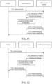
- FIG. 10 illustrates a flowchart of a method for configuring an uplink positioning reference signal provided by an embodiment of the present application. The method can be applied in the system shown in FIG. 1 . The method includes the following steps.
- Step 1002 a terminal sends a request message to a network device.
- the request message is used to request the network device to configure an uplink positioning reference signal for the terminal.
- the request message also carries a reason for the terminal to request the uplink positioning reference signal.
- the reason for the terminal to request the uplink positioning reference signal includes at least one of the following:
- the terminal will send the above-described request message to the network device if at least one of the following conditions is satisfied:
- the above conditions include at least one of the following conditions:
- the request message sent by the terminal to the network device is carried in an RRC resume request message.
- Step 1004 the network device determines an uplink positioning reference signal configuration.
- the uplink positioning reference signal configuration is determined by the network device in response to the request message from the terminal.
- the network device will respond to the request message, and determine the uplink positioning reference signal configuration for the terminal.
- the network device belongs to a serving cell of the terminal.
- Step 1006 the network device sends the uplink positioning reference signal configuration to the terminal.
- the network device After the network device determines the uplink positioning reference signal configuration for the terminal, it will send its determined uplink positioning reference signal configuration to the terminal, thereby realizing the configuration of the uplink positioning reference signal for the terminal. Optionally, the network device will also send its determined uplink positioning reference signal configuration to the LMF network element.
- the uplink positioning reference signal configuration sent by the network device to the terminal is carried in an RRC message.
- the RRC message includes at least one of an RRC release message, an RRC reconfiguration message, or an RRC setup message.
- the uplink positioning reference signal configuration sent by the network device to the LMF network element is carried in an NRPPa message.
- the NRPPa message includes at least one of a UE association NRPPa message or a non-UE association NRPPa message.
- Step 1008 the network device sends the uplink positioning reference signal configuration to the LMF network element.
- the network device After determining the uplink positioning reference signal configuration for the terminal, the network device will also send its determined uplink positioning reference signal configuration to the LMF network element, and the LMF network element is able to be informed of the uplink positioning reference signal configured for the terminal based on the uplink positioning reference signal configuration sent by the network device.
- the method provided in this embodiment by having the terminal actively request the network device to configure the uplink positioning reference signal, is able to realize that when the terminal releases the stored uplink positioning reference signal configuration, the uplink positioning reference signal is instantaneously configured for the terminal according to the request of the terminal, thereby being able to reduce the delay in configuring the uplink positioning reference signal for the terminal, which in turn reduces the positioning delay and improves the flexibility of configuring the uplink positioning reference signal.
- FIG. 11 illustrates a flowchart of a method for configuring an uplink positioning reference signal provided by an embodiment of the present application. The method can be applied in the system shown in FIG. 1 . The method includes the following steps.
- Step 1102 a terminal sends a request message to an LMF network element.
- the request message is used to request the LMF network element to configure an uplink positioning reference signal for the terminal.
- the request message also carries a reason for the terminal to request the uplink positioning reference signal.
- the reason for the terminal to request the uplink positioning reference signal includes at least one of the following:
- the terminal will send the above-described request message to the LMF network element if at least one of the following conditions is satisfied:
- the above conditions include at least one of the following conditions:
- the terminal sends the request message to the LMF network element in at least two ways as follows.
- the terminal sends the request message to the LMF network element via the network device based on an RRC message, such as an RRC resume request message, i.e., the network device transparently transmits the request message sent by the terminal to the LMF network element.
- RRC message such as an RRC resume request message
- the terminal will send a request message to the network device based on the RRC resume request message.
- the RRC resume request message carries the UL Information Transfer
- the UL Information Transfer carries the request message.
- the network device after receiving the above information sent by the terminal, will send the UL Information Transfer to the LMF network element.
- the UL Information Transfer refers to the Uplink NAS Transport.
- the network device that transparently transmits the request message of the terminal may belong or may not belong to a serving cell of the terminal.
- the request message is sent directly to the LMF network element via a LPP: in the case where the terminal sends the request message directly to the LMF network element, the request message sent by the terminal to the LMF network element is carried in a LPP message.
- the terminal can also send the request message to the LMF network element in other ways, and the above implementations are used as examples only and are not to be taken as a limitation of the solutions provided by the embodiments of the present application.
- Step 1104 the LMF network element requests a network device to configure an uplink positioning reference signal for the terminal.
- the LMF network element will respond to the request message and request the network device to configure the uplink positioning reference signal for the terminal.
- the network device belongs to a serving cell of the terminal.
- the LMF network element requests the network device to configure the uplink positioning reference signal for the terminal via an NRPPa message.
- the NRPPa message includes at least one of a UE association NRPPa message or a non-UE association NRPPa message.
- Step 1106 the network device determines an uplink positioning reference signal configuration.
- This uplink positioning reference signal configuration is determined by the network device in response to a request from the LMF network element.
- the LMF network element requests the network device to configure the uplink positioning reference signal for the terminal
- the network device will respond to the request and determine the uplink positioning reference signal configuration for the terminal.
- Step 1108 the network device sends the uplink positioning reference signal configuration to the LMF network element.
- the network device After determining the uplink positioning reference signal configuration for the terminal, the network device will send its determined uplink positioning reference signal configuration to the LMF network element. Optionally, the network device sends its determined uplink positioning reference signal configuration to the LMF network element via an NRPPa message.
- the NRPPa message includes at least one of a UE association NRPPa message or a non-UE association NRPPa message.
- Step 1110 the LMF network element sends the uplink positioning reference signal configuration to the terminal.
- the LMF network element After receiving the uplink positioning reference signal configuration determined by the network device, the LMF network element will send the uplink positioning reference signal configuration determined by the network device to the terminal, thereby realizing the configuration of the uplink positioning reference signal for the terminal.
- the uplink positioning reference signal configuration sent by the LMF network element to the terminal is carried in a LPP message.
- the method provided in this embodiment by having the terminal actively request the LMF network element to configure the uplink positioning reference signal, is able to realize that when the terminal releases the stored uplink positioning reference signal configuration, the uplink positioning reference signal is instantaneously configured for the terminal according to the request of the terminal, thereby being able to reduce the delay in configuring the uplink positioning reference signal for the terminal, which in turn reduces the positioning delay and improves the flexibility of configuring the uplink positioning reference signal.
- FIG. 12 illustrates a flowchart of a method for configuring an uplink positioning reference signal provided by an embodiment of the present application. The method can be applied in the system shown in FIG. 1 . The method includes the following steps.
- Step 1202 a terminal sends a request message to an LMF network element.
- the request message is used to request the LMF network element to configure an uplink positioning reference signal for the terminal.
- the request message further carries a reason for the terminal to request the uplink positioning reference signal.
- the reason for the terminal to request the uplink positioning reference signal includes at least one of the following:
- the terminal will send the above-described request message to the LMF network element if at least one of the following conditions is satisfied:
- the above conditions include at least one of the following conditions:
- the terminal sends the request message to the LMF network element in at least two ways as follows.
- the terminal sends the request message to the LMF network element via the network device based on an RRC message, such as an RRC resume request message, i.e., the network device transparently transmits the request message sent by the terminal to the LMF network element.
- RRC message such as an RRC resume request message
- the terminal will send a request message to the network device based on the RRC resume request message.
- the RRC resume request message carries the UL Information Transfer
- the UL Information Transfer carries the request message.
- the network device after receiving the above information sent by the terminal, will send the UL Information Transfer to the LMF network element.
- the UL Information Transfer refers to the Uplink NAS Transport.
- the network device that transparently transmits the request message of the terminal may belong or may not belong to a serving cell of the terminal.
- the request message is sent directly to the LMF network element via a LPP: in the case where the terminal sends the request message directly to the LMF network element, the request message sent by the terminal to the LMF network element is carried in a LPP message.
- the terminal can also send the request message to the LMF network element in other ways, and the above implementations are used as examples only and are not to be taken as a limitation of the solutions provided by the embodiments of the present application.
- Step 1204 the LMF network element requests the network device to configure the uplink positioning reference signal for the terminal.
- the LMF network element will respond to the request message and request the network device to configure the uplink positioning reference signal for the terminal.
- the network device belongs to a serving cell of the terminal.
- the LMF network element requests the network device to configure an uplink positioning reference signal for the terminal via an NRPPa message.
- the NRPPa message includes at least one of a UE association NRPPa message or a non-UE association NRPPa message.
- Step 1206 the network device determines an uplink positioning reference signal configuration.
- This uplink positioning reference signal configuration is determined by the network device in response to a request from the LMF network element.
- the LMF network element requests the network device to configure the uplink positioning reference signal for the terminal
- the network device will respond to the request and determine the uplink positioning reference signal configuration for the terminal.
- Step 1208 the network device sends the uplink positioning reference signal configuration to the terminal.
- the network device After determining the uplink positioning reference signal configuration for the terminal, the network device will send its determined uplink positioning reference signal configuration directly to the terminal, thereby realizing the configuration of the uplink positioning reference signal for the terminal.
- the uplink positioning reference signal configuration sent by the network device to the terminal is carried in an RRC message.
- the RRC message includes at least one of an RRC release message, an RRC reconfiguration message, or an RRC setup message.
- the network device sends its determined uplink positioning reference signal configuration to the LMF network element via an NRPPa message.
- the NRPPa message includes at least one of a UE association NRPPa message or a non-UE association NRPPa message.
- Step 1210 the network device sends the uplink positioning reference signal configuration to the LMF network element.
- the network device After determining the uplink positioning reference signal configuration for the terminal, the network device will also send its determined uplink positioning reference signal configuration to the LMF network element, and the LMF network element is able to be informed of the uplink positioning reference signal configured for the terminal based on the uplink positioning reference signal configuration sent by the network device.
- the method provided in this embodiment by having the terminal actively request the LMF network element to configure the uplink positioning reference signal, is able to realize that when the terminal releases the stored uplink positioning reference signal configuration, the uplink positioning reference signal is instantaneously configured for the terminal according to the request of the terminal, thereby being able to reduce the delay in configuring the uplink positioning reference signal for the terminal, which in turn reduces the positioning delay and improves the flexibility of configuring the uplink positioning reference signal.
- FIG. 13 illustrates a block diagram of a structure of an apparatus for configuring an uplink positioning reference signal provided by an exemplary embodiment of the present application. As shown in FIG. 13 , the apparatus includes:
- the sending module 1301 is configured to: send the request message to the network device and/or the LMF network element in response to at least one of following conditions being satisfied:
- the request message sent by the terminal to the network device is carried in a RRC resume request message.
- the apparatus further includes:
- the uplink positioning reference signal configuration sent by the network device to the terminal is carried in a RRC message.
- the network device sends the uplink positioning reference signal configuration to the LMF network element.
- the uplink positioning reference signal configuration sent by the network device to the LMF network element is carried in a New Radio Positioning Protocol A message.
- the sending module 1301 is configured to: send the request message to the LMF network element via the network device based on a RRC resume request message.
- the sending module 1301 is configured to:
- the request message sent by the terminal to the LMF network element is carried in a LPP message.
- the LMF network element requests the network device to configure the uplink positioning reference signal for the terminal.
- the network device sends an uplink positioning reference signal configuration to the terminal, where the uplink positioning reference signal configuration is determined by the network device in response to the request from the LMF network element.
- the network device sends an uplink positioning reference signal configuration to the LMF network element, where the uplink positioning reference signal configuration is determined by the network device in response to the request from the LMF network element.
- the device further comprises:
- the uplink positioning reference signal configuration sent by the LMF network element to the terminal is carried in a LPP message.
- the request message further carries a reason for the terminal to request the uplink positioning reference signal.
- the reason for the terminal to request the uplink positioning reference signal includes at least one of:
- FIG. 14 illustrates a block diagram of a structure of an apparatus for configuring an uplink positioning reference signal provided by an exemplary embodiment of the present application. As shown in FIG. 14 , the apparatus includes:
- the request message sent by the terminal to the network device is carried in a RRC resume request message.
- the apparatus further includes:
- the uplink positioning reference signal configuration sent by the network device to the terminal is carried in a RRC message.
- the apparatus further includes: a sending module 1403 configured to send the uplink positioning reference signal configuration to an LMF network element.
- the uplink positioning reference signal configuration sent by the network device to the LMF network element is carried in a New Radio Positioning Protocol A message.
- the receiving module 1401 is configured to:
- the apparatus further includes:
- the apparatus further includes:
- the LMF network element sends an uplink positioning reference signal configuration to the terminal; where the uplink positioning reference signal configuration is determined by the network device in response to the request from the LMF network element.
- the uplink positioning reference signal configuration sent by the LMF network element to the terminal is carried in a LPP message.
- the request message further carries a reason for the terminal to request the uplink positioning reference signal.
- the reason for the terminal to request the uplink positioning reference signal includes at least one of:
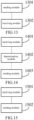
- FIG. 15 illustrates a block diagram of a structure of an apparatus for configuring an uplink positioning reference signal provided by an exemplary embodiment of the present application. As shown in FIG. 15 , the apparatus includes:
- the receiving module 1501 is configured to: receive the request message sent via a network device from the terminal based on a RRC resume request message.
- the receiving module 1501 is configured to:
- the request message sent by the terminal to the LMF network element is carried in a LPP message.
- the apparatus further includes: a sending module 1502 configured to request the network device to configure the uplink positioning reference signal for the terminal.
- the network device sends an uplink positioning reference signal configuration to the terminal; and the uplink positioning reference signal configuration is determined by the network device in response to the request from the LMF network element.
- the receiving module 1501 is configured to:
- the apparatus further includes:
- the uplink positioning reference signal configuration sent by the LMF network element to the terminal is carried in a LPP message.
- the receiving module 1501 is configured to:
- the uplink positioning reference signal configuration sent by the network device to the LMF network element is carried in a New Radio Positioning Protocol A message.
- the request message further carries a reason for the terminal to request the uplink positioning reference signal.
- the reason for the terminal to request the uplink positioning reference signal includes at least one of:
- the apparatus provided by the above embodiments is only exemplified by the division of the above-described functional modules in realizing its functions, and in actual application, the above-described functions can be assigned to be completed by different functional modules according to actual needs, i.e., the content structure of the apparatus can be divided into different functional modules in order to complete all or part of the above-described functions.
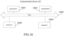
- FIG. 16 illustrates a schematic diagram of a structure of a communication device (terminal device or network device) provided by an exemplary embodiment of the present application.
- the communication device 160 includes a processor 1601, a receiver 1602, a transmitter 1603, a memory 1604, and a bus 1605.
- the processor 1601 includes one or more processing cores, and the processor 1601 performs various functional applications as well as information processing by running software programs as well as modules.
- the receiver 1602 and the transmitter 1603 may be implemented as a communication component, which may be a communication chip.
- the memory 1604 is connected to the processor 1601 via bus 1605.
- the memory 1604 may be used to store the at least one instruction, and the processor 1601 is used to execute the at least one instruction to implement the various steps in the method embodiments described above.
- volatile or non-volatile storage devices include, but are not limited to: disks or optical disks, electrically Erasable Programmable Read Only Memory (EEPROM), Erasable Programmable Erasable Programmable Read Only Memory (EPROM), Static Random Access Memory (SRAM), Read-Only Memory (ROM), Magnetic Memory, Flash Memory, Programmable Read-Only Memory (PROM).
- EEPROM electrically Erasable Programmable Read Only Memory
- EPROM Erasable Programmable Erasable Programmable Read Only Memory
- SRAM Static Random Access Memory
- ROM Read-Only Memory
- ROM Magnetic Memory
- Flash Memory Programmable Read-Only Memory
- the processor and the transceiver in the communication device involved in the embodiments of the present application may be realized together as a communication chip, or the transceiver may form the communication chip alone.
- the transmitter in the transceiver performs sending steps performed by the terminal in any one of the methods described above, and the receiver in the transceiver performs receiving steps performed by the terminal in any one of the methods described above, and the processor performs steps other than the sending and receiving steps, which will not be described herein.
- the processor and the transceiver in the communication device involved in the embodiments of the present application may be realized together as a communication chip, or the transceiver may form the communication chip alone.
- the transmitter in the transceiver performs the sending steps performed by the network device in any one of the methods described above
- the receiver in the transceiver performs the receiving steps performed by the network device in any one of the methods described above
- the processor performs steps other than the sending and receiving steps, which will not be described herein.
- a computer-readable storage medium having stored therein at least one instruction, at least one segment of a program, a code set, or a set of instructions.
- the at least one instruction, the at least one segment of a program, the code set or the set of instructions is loaded and executed by the processor to implement the method for configuring the uplink positioning reference signal provided by each of the above method embodiments.
- a chip including a programmable logic circuit and/or a program instruction for implementing the method for configuring the uplink positioning reference signal provided by each of the above method embodiments when the chip is operated on a communication device.
- a computer program product that, when run on a processor of a computer device, causes the computer device to perform the method for configuring the uplink positioning reference signal described above.
- the functions described in the embodiments of the present application may be implemented using hardware, software, firmware, or any combination thereof.
- the functions may be stored in a computer-readable medium or transmitted as one or more instructions or code on a computer-readable medium.
- the computer-readable medium includes a computer storage medium and a communication medium, where the communication medium includes any medium that facilitates the transmission of a computer program from one location to another.
- the storage medium can be any available medium that can be accessed by a general-purpose or special-purpose computer.
Landscapes
- Engineering & Computer Science (AREA)
- Signal Processing (AREA)
- Computer Networks & Wireless Communication (AREA)
- Mobile Radio Communication Systems (AREA)
Applications Claiming Priority (1)
| Application Number | Priority Date | Filing Date | Title |
|---|---|---|---|
| PCT/CN2022/087190 WO2023197320A1 (zh) | 2022-04-15 | 2022-04-15 | 上行定位参考信号的配置方法、装置、设备及存储介质 |
Publications (2)
| Publication Number | Publication Date |
|---|---|
| EP4510722A1 true EP4510722A1 (de) | 2025-02-19 |
| EP4510722A4 EP4510722A4 (de) | 2025-06-11 |
Family
ID=88328657
Family Applications (1)
| Application Number | Title | Priority Date | Filing Date |
|---|---|---|---|
| EP22936965.7A Pending EP4510722A4 (de) | 2022-04-15 | 2022-04-15 | Verfahren und vorrichtung zur konfiguration eines uplink-positionierungsreferenzsignals sowie vorrichtung und speichermedium |
Country Status (4)
| Country | Link |
|---|---|
| US (1) | US20250261155A1 (de) |
| EP (1) | EP4510722A4 (de) |
| CN (1) | CN117280791A (de) |
| WO (1) | WO2023197320A1 (de) |
Families Citing this family (1)
| Publication number | Priority date | Publication date | Assignee | Title |
|---|---|---|---|---|
| WO2026065548A1 (zh) * | 2024-09-30 | 2026-04-02 | 北京小米移动软件有限公司 | 一种通信方法及设备、通信系统、通信设备、存储介质 |
Family Cites Families (3)
| Publication number | Priority date | Publication date | Assignee | Title |
|---|---|---|---|---|
| KR20230078643A (ko) * | 2020-09-22 | 2023-06-02 | 퀄컴 인코포레이티드 | 기준 신호 구성 포지셔닝 및 관리 |
| WO2022067505A1 (zh) * | 2020-09-29 | 2022-04-07 | 华为技术有限公司 | 通信方法及装置 |
| CN112469131B (zh) * | 2020-12-23 | 2023-04-18 | Oppo(重庆)智能科技有限公司 | 一种配置srs资源符号数的方法及终端设备 |
-
2022
- 2022-04-15 US US18/856,700 patent/US20250261155A1/en active Pending
- 2022-04-15 WO PCT/CN2022/087190 patent/WO2023197320A1/zh not_active Ceased
- 2022-04-15 CN CN202280001216.2A patent/CN117280791A/zh active Pending
- 2022-04-15 EP EP22936965.7A patent/EP4510722A4/de active Pending
Also Published As
| Publication number | Publication date |
|---|---|
| WO2023197320A1 (zh) | 2023-10-19 |
| US20250261155A1 (en) | 2025-08-14 |
| CN117280791A (zh) | 2023-12-22 |
| EP4510722A4 (de) | 2025-06-11 |
Similar Documents
| Publication | Publication Date | Title |
|---|---|---|
| CN111491338B (zh) | 上下文存储方法及装置 | |
| US20250168693A1 (en) | Communications Method and Apparatus | |
| US11012825B2 (en) | Short message transmission method, device, and system | |
| US20100248768A1 (en) | Wireless Communication Terminal And Management Device In A Wireless Communication System And Method Thereof | |
| US12495395B2 (en) | Communication method and apparatus, terminal device and network device | |
| US12335837B2 (en) | Data transmission method, communication device, and chip | |
| CN114007204A (zh) | 基于中继通信与直连通信的通信选择方法和设备 | |
| CN110784912B (zh) | 一种会话对应关系的管理方法和终端设备 | |
| CN116648965A (zh) | 一种rrc状态转换的方法及装置、终端设备 | |
| EP4510722A1 (de) | Verfahren und vorrichtung zur konfiguration eines uplink-positionierungsreferenzsignals sowie vorrichtung und speichermedium | |
| CN119138026A (zh) | 用于控制网络中的用户设备的方法和装置 | |
| CN116686391A (zh) | 通信方法、装置、设备及存储介质 | |
| EP4503781A1 (de) | Verfahren und vorrichtungen zur konfiguration eines uplink-positionierungsreferenzsignals sowie vorrichtungen und speichermedium | |
| CN116074847A (zh) | 一种信号传输方法及装置、终端设备 | |
| US10142877B2 (en) | Management device, communication system, and communication control method | |
| CN110913507A (zh) | 通信方法和装置 | |
| CN117222054A (zh) | 状态转换方法、装置、设备及存储介质 | |
| EP4503761A1 (de) | Verfahren und vorrichtungen zur konfiguration eines uplink-positionierungsreferenzsignals sowie vorrichtungen und speichermedium | |
| KR20220163439A (ko) | 네트워크 요청 등록 절차 개시 | |
| CN116349326A (zh) | 无线通信方法、设备及存储介质 | |
| CN112929867A (zh) | 一种寻呼方法和装置 | |
| CN116134912B (zh) | 一种通信方法及装置、网络设备、终端设备 | |
| CN121604185A (zh) | 一种通信方法及装置 | |
| CN120201476A (zh) | 通信方法和通信装置 | |
| CN117242838A (zh) | 上行定位参考信号的配置方法、装置、设备及存储介质 |
Legal Events
| Date | Code | Title | Description |
|---|---|---|---|
| STAA | Information on the status of an ep patent application or granted ep patent |
Free format text: STATUS: THE INTERNATIONAL PUBLICATION HAS BEEN MADE |
|
| PUAI | Public reference made under article 153(3) epc to a published international application that has entered the european phase |
Free format text: ORIGINAL CODE: 0009012 |
|
| STAA | Information on the status of an ep patent application or granted ep patent |
Free format text: STATUS: REQUEST FOR EXAMINATION WAS MADE |
|
| 17P | Request for examination filed |
Effective date: 20241115 |
|
| AK | Designated contracting states |
Kind code of ref document: A1 Designated state(s): AL AT BE BG CH CY CZ DE DK EE ES FI FR GB GR HR HU IE IS IT LI LT LU LV MC MK MT NL NO PL PT RO RS SE SI SK SM TR |
|
| REG | Reference to a national code |
Ref country code: DE Ref legal event code: R079 Free format text: PREVIOUS MAIN CLASS: H04W0064000000 Ipc: H04L0005000000 |
|
| A4 | Supplementary search report drawn up and despatched |
Effective date: 20250513 |
|
| RIC1 | Information provided on ipc code assigned before grant |
Ipc: H04L 5/00 20060101AFI20250507BHEP |
|
| DAV | Request for validation of the european patent (deleted) | ||
| DAX | Request for extension of the european patent (deleted) |