EP4512224A1 - Entladerohr-verriegelung für landwirtschaftliches fahrzeug - Google Patents
Entladerohr-verriegelung für landwirtschaftliches fahrzeug Download PDFInfo
- Publication number
- EP4512224A1 EP4512224A1 EP24193648.3A EP24193648A EP4512224A1 EP 4512224 A1 EP4512224 A1 EP 4512224A1 EP 24193648 A EP24193648 A EP 24193648A EP 4512224 A1 EP4512224 A1 EP 4512224A1
- Authority
- EP
- European Patent Office
- Prior art keywords
- combine harvester
- pin
- cradle member
- unload tube
- pivotable
- Prior art date
- Legal status (The legal status is an assumption and is not a legal conclusion. Google has not performed a legal analysis and makes no representation as to the accuracy of the status listed.)
- Granted
Links
Images


Classifications
-
- A—HUMAN NECESSITIES
- A01—AGRICULTURE; FORESTRY; ANIMAL HUSBANDRY; HUNTING; TRAPPING; FISHING
- A01D—HARVESTING; MOWING
- A01D41/00—Combines, i.e. harvesters or mowers combined with threshing devices
- A01D41/12—Details of combines
- A01D41/1208—Tanks for grain or chaff
- A01D41/1217—Unloading mechanisms
-
- A—HUMAN NECESSITIES
- A01—AGRICULTURE; FORESTRY; ANIMAL HUSBANDRY; HUNTING; TRAPPING; FISHING
- A01D—HARVESTING; MOWING
- A01D90/00—Vehicles for carrying harvested crops with means for selfloading or unloading
- A01D90/10—Unloading means
Definitions
- the present invention relates to a lock for an unload tube for use with an agricultural vehicle, such as a combine harvester.
- the unload tube may also be referred to in the art as an unloading conveyor or unload auger.
- An unload tube of an agricultural vehicle such as a combine harvester, is used to distribute grain from the grain tank of the combine and into a grain storage or transport container.
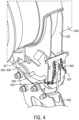
- a locking device for retaining (i.e., locking) the unload tube in a docked (i.e., stowed) position during transport of the agricultural vehicle.
- a combine harvester includes a frame member, an unload tube, a pivotable cradle member and a locking device.
- the unload tube is configured for expelling clean grain from a clean grain tank of the combine harvester.
- the unload tube is moveable relative to the clean grain tank and the frame member between a stowed position and a deployed position.
- the pivotable cradle member is pivotably mounted with respect to the frame member for releasably receiving the unload tube.
- the pivotable cradle member includes a surface that is shaped for bearing on an exterior surface of the unload tube.
- the pivotable cradle member is pivotable between a first rotational position when the unload tube is maintained in the stowed position and a second rotational position when the unload tube is maintained in the deployed position.
- the locking device locks together the unload tube, the frame member and the pivotable cradle member when the unload tube is maintained in the stowed position.
- an agricultural harvester in the form of a combine 10, which generally includes a chassis 12, ground engaging wheels 14 and 16, header 18, feeder housing 20, operator cab 22, threshing and separating system 24, cleaning system 26, grain tank 28, and unloading conveyor 30.
- Front wheels 14 are larger flotation type wheels, and rear wheels 16 are smaller steerable wheels. Motive force is selectively applied to front wheels 14 through a power plant in the form of a diesel engine 32 and a transmission (not shown). Although combine 10 is shown as including wheels, is also to be understood that combine 10 may include tracks.
- Header 18 is mounted to the front of combine 10 and includes a cutter bar 34 for severing crops from a field during forward motion of combine 10.
- a rotatable reel 36 feeds the crop into header 18, and a double auger 38 feeds the severed crop laterally inwardly from each side toward feeder housing 20.
- Feeder housing 20 conveys the cut crop to threshing and separating system 24, and is selectively vertically movable using appropriate actuators, such as hydraulic cylinders (not shown).
- Threshing and separating system 24 generally includes a rotor 40 at least partially enclosed by and rotatable within a corresponding perforated concave 42.
- the cut crops are threshed and separated by the rotation of rotor 40 within concave 42, and larger elements, such as stalks, leaves and the like are discharged from the rear of combine 10.
- Smaller elements of crop material including grain and non-grain crop material, including particles lighter than grain, such as chaff, dust and straw, are discharged through perforations of concave 42.
- Threshing and separating system 24 can also be a different type of system, such as a system with a transverse rotor rather than an axial rotor, etc.
- Cleaning system 26 may include an optional pre-cleaning sieve 46, an upper sieve 48 (also known as a chaffer sieve), a lower sieve 50 (also known as a cleaning sieve), and a cleaning fan 52.
- the upper sieve 48 and lower sieve 50 can be carried within a common framework. Grain on sieves 46, 48 and 50 is subjected to a cleaning action by fan 52 which provides an air flow through the sieves to remove chaff and other impurities such as dust from the grain by making this material airborne for discharge from straw hood 54 of combine 10.
- Grain pan 44 and pre-cleaning sieve 46 oscillate in a fore-to-aft manner to transport the grain and finer non-grain crop material to the upper surface of upper sieve 48.
- Upper sieve 48 and lower sieve 50 are vertically arranged relative to each other, and likewise oscillate in a fore-to-aft manner to spread the grain across sieves 48, 50, while permitting the passage of cleaned grain by gravity through the openings of sieves 48, 50.
- Clean grain falls to a clean grain auger 56 positioned crosswise below and toward the front of lower sieve 50.
- Clean grain auger 56 receives clean grain from each sieve 48, 50 and from bottom pan 58 of cleaning system 26.
- Clean grain auger 56 conveys the clean grain laterally to a generally vertically arranged grain elevator 60 for transport to grain tank 28.
- Tailings from cleaning system 26 fall to a tailings auger trough 62.
- the tailings are transported via tailings auger 64 and return auger 66 to the upstream end of cleaning system 26 for repeated cleaning action.
- a pair of grain tank augers 68 at the bottom of grain tank 28 convey the clean grain laterally within grain tank 28 to unloading conveyor 30 for discharge from combine 10.
- Unloading conveyor 30 may also be referred to in the art as an unload tube.
Landscapes
- Life Sciences & Earth Sciences (AREA)
- Environmental Sciences (AREA)
- Threshing Machine Elements (AREA)
- Harvester Elements (AREA)
Applications Claiming Priority (1)
| Application Number | Priority Date | Filing Date | Title |
|---|---|---|---|
| US18/233,387 US12588602B2 (en) | 2023-08-14 | 2023-08-14 | Unload tube lock for agricultural vehicle |
Publications (2)
| Publication Number | Publication Date |
|---|---|
| EP4512224A1 true EP4512224A1 (de) | 2025-02-26 |
| EP4512224B1 EP4512224B1 (de) | 2026-04-01 |
Family
ID=92295936
Family Applications (1)
| Application Number | Title | Priority Date | Filing Date |
|---|---|---|---|
| EP24193648.3A Active EP4512224B1 (de) | 2023-08-14 | 2024-08-08 | Entladerohr-verriegelung für landwirtschaftliches fahrzeug |
Country Status (2)
| Country | Link |
|---|---|
| US (1) | US12588602B2 (de) |
| EP (1) | EP4512224B1 (de) |
Citations (6)
| Publication number | Priority date | Publication date | Assignee | Title |
|---|---|---|---|---|
| US3521768A (en) * | 1968-07-02 | 1970-07-28 | Deere & Co | Support for a grain tank discharge pipe |
| US4522552A (en) * | 1982-06-03 | 1985-06-11 | Pietro Laverda S.P.A. | Combine harvesters |
| DE19802199A1 (de) * | 1998-01-22 | 1999-07-29 | Ernst Dipl Ing Schumacher | Entleervorrichtung für einen Behälter |
| JP2005176697A (ja) * | 2003-12-18 | 2005-07-07 | Kubota Corp | コンバインの揚穀装置支持機構 |
| EP2489253A1 (de) * | 2011-02-17 | 2012-08-22 | LAVERDA S.p.A. | Mähdrescherentladesystem |
| US10448568B2 (en) * | 2015-10-14 | 2019-10-22 | Cnh Industrial America Llc | Automatically securing unloading auger support |
Family Cites Families (4)
| Publication number | Priority date | Publication date | Assignee | Title |
|---|---|---|---|---|
| US2743571A (en) | 1952-10-09 | 1956-05-01 | Int Harvester Co | Grain tank discharge conveyor for harvesters |
| US4094254A (en) * | 1976-12-27 | 1978-06-13 | Koranda Clarence J | Lock for railway hopper car gate railway car gate lock |
| US5876176A (en) * | 1996-05-10 | 1999-03-02 | Unverferth Manufacturing Co., Inc. | Stowage latch assembly for auger |
| US6981833B2 (en) | 2002-07-19 | 2006-01-03 | Cnh America Llc | Work vehicle with dual mode unloader apparatus and method |
-
2023
- 2023-08-14 US US18/233,387 patent/US12588602B2/en active Active
-
2024
- 2024-08-08 EP EP24193648.3A patent/EP4512224B1/de active Active
Patent Citations (6)
| Publication number | Priority date | Publication date | Assignee | Title |
|---|---|---|---|---|
| US3521768A (en) * | 1968-07-02 | 1970-07-28 | Deere & Co | Support for a grain tank discharge pipe |
| US4522552A (en) * | 1982-06-03 | 1985-06-11 | Pietro Laverda S.P.A. | Combine harvesters |
| DE19802199A1 (de) * | 1998-01-22 | 1999-07-29 | Ernst Dipl Ing Schumacher | Entleervorrichtung für einen Behälter |
| JP2005176697A (ja) * | 2003-12-18 | 2005-07-07 | Kubota Corp | コンバインの揚穀装置支持機構 |
| EP2489253A1 (de) * | 2011-02-17 | 2012-08-22 | LAVERDA S.p.A. | Mähdrescherentladesystem |
| US10448568B2 (en) * | 2015-10-14 | 2019-10-22 | Cnh Industrial America Llc | Automatically securing unloading auger support |
Also Published As
| Publication number | Publication date |
|---|---|
| EP4512224B1 (de) | 2026-04-01 |
| US20250057082A1 (en) | 2025-02-20 |
| US12588602B2 (en) | 2026-03-31 |
Similar Documents
| Publication | Publication Date | Title |
|---|---|---|
| US11277969B2 (en) | Adjusting system for fingerstyle grates of an agricultural harvester | |
| US10588261B2 (en) | Residue handling system for an agricultural harvester | |
| EP3707987B1 (de) | Sieb für landwirtschaftliche erntemaschine mit verstellbaren lamellen und zugehörige verstellvorrichtung | |
| US10111384B2 (en) | Agricultural chopper with linked counter knives and shear bar | |
| US12477979B2 (en) | Moveable panel for bypassing chopper of agricultural vehicle | |
| EP2745673B1 (de) | Schiebegelenk einer Mähdrescherquerschüttlersteuerung | |
| EP3172959A1 (de) | Häcksler und streuer für eine landwirtschaftliche erntemaschine | |
| US11259466B2 (en) | Agricultural elevator supplied by multiple cross augers | |
| EP4491007A1 (de) | Auslauftülle für landwirtschaftliches fahrzeug | |
| EP4512224B1 (de) | Entladerohr-verriegelung für landwirtschaftliches fahrzeug | |
| EP4494440A1 (de) | Hebesystem für eine befüllschnecke eines mähdreschers | |
| EP3618603B1 (de) | Übertotpunktverriegelungssystem für einen spreukasten einer landwirtschaftlichen erntemaschine | |
| EP4385307A1 (de) | Korntankverstärkung für ein landwirtschaftliches fahrzeug | |
| EP4501098A1 (de) | Entladungsrohr-schwenkzylinderhalterung für landwirtschaftliche fahrzeuge | |
| EP3157319B1 (de) | Strohschüttleranordnung für eine landwirtschaftliche erntemaschine | |
| CN117413679B (zh) | 联合收割机拖挂件内的集成步升装置 | |
| EP4461118A1 (de) | Entladerohr für landwirtschaftliches fahrzeug |
Legal Events
| Date | Code | Title | Description |
|---|---|---|---|
| PUAI | Public reference made under article 153(3) epc to a published international application that has entered the european phase |
Free format text: ORIGINAL CODE: 0009012 |
|
| STAA | Information on the status of an ep patent application or granted ep patent |
Free format text: STATUS: THE APPLICATION HAS BEEN PUBLISHED |
|
| AK | Designated contracting states |
Kind code of ref document: A1 Designated state(s): AL AT BE BG CH CY CZ DE DK EE ES FI FR GB GR HR HU IE IS IT LI LT LU LV MC ME MK MT NL NO PL PT RO RS SE SI SK SM TR |
|
| STAA | Information on the status of an ep patent application or granted ep patent |
Free format text: STATUS: REQUEST FOR EXAMINATION WAS MADE |
|
| 17P | Request for examination filed |
Effective date: 20250826 |
|
| GRAP | Despatch of communication of intention to grant a patent |
Free format text: ORIGINAL CODE: EPIDOSNIGR1 |
|
| STAA | Information on the status of an ep patent application or granted ep patent |
Free format text: STATUS: GRANT OF PATENT IS INTENDED |
|
| RIC1 | Information provided on ipc code assigned before grant |
Ipc: A01D 41/12 20060101AFI20251028BHEP |
|
| INTG | Intention to grant announced |
Effective date: 20251107 |
|
| GRAS | Grant fee paid |
Free format text: ORIGINAL CODE: EPIDOSNIGR3 |
|
| GRAA | (expected) grant |
Free format text: ORIGINAL CODE: 0009210 |
|
| STAA | Information on the status of an ep patent application or granted ep patent |
Free format text: STATUS: THE PATENT HAS BEEN GRANTED |
|
| AK | Designated contracting states |
Kind code of ref document: B1 Designated state(s): AL AT BE BG CH CY CZ DE DK EE ES FI FR GB GR HR HU IE IS IT LI LT LU LV MC ME MK MT NL NO PL PT RO RS SE SI SK SM TR |
|
| REG | Reference to a national code |
Ref country code: CH Ref legal event code: F10 Free format text: ST27 STATUS EVENT CODE: U-0-0-F10-F00 (AS PROVIDED BY THE NATIONAL OFFICE) Effective date: 20260401 Ref country code: GB Ref legal event code: FG4D |
|
| REG | Reference to a national code |
Ref country code: DE Ref legal event code: R096 Ref document number: 602024003601 Country of ref document: DE |
|
| REG | Reference to a national code |
Ref country code: IE Ref legal event code: FG4D |