EP4512294A1 - Unité de commande et procédé de détermination de la position d'un pare-chocs - Google Patents
Unité de commande et procédé de détermination de la position d'un pare-chocs Download PDFInfo
- Publication number
- EP4512294A1 EP4512294A1 EP24184917.3A EP24184917A EP4512294A1 EP 4512294 A1 EP4512294 A1 EP 4512294A1 EP 24184917 A EP24184917 A EP 24184917A EP 4512294 A1 EP4512294 A1 EP 4512294A1
- Authority
- EP
- European Patent Office
- Prior art keywords
- bumper
- control unit
- cleaning device
- reference points
- camera
- Prior art date
- Legal status (The legal status is an assumption and is not a legal conclusion. Google has not performed a legal analysis and makes no representation as to the accuracy of the status listed.)
- Granted
Links
Images
Classifications
-
- G—PHYSICS
- G06—COMPUTING OR CALCULATING; COUNTING
- G06T—IMAGE DATA PROCESSING OR GENERATION, IN GENERAL
- G06T7/00—Image analysis
- G06T7/70—Determining position or orientation of objects or cameras
- G06T7/73—Determining position or orientation of objects or cameras using feature-based methods
- G06T7/74—Determining position or orientation of objects or cameras using feature-based methods involving reference images or patches
-
- A—HUMAN NECESSITIES
- A47—FURNITURE; DOMESTIC ARTICLES OR APPLIANCES; COFFEE MILLS; SPICE MILLS; SUCTION CLEANERS IN GENERAL
- A47L—DOMESTIC WASHING OR CLEANING; SUCTION CLEANERS IN GENERAL
- A47L9/00—Details or accessories of suction cleaners, e.g. mechanical means for controlling the suction or for effecting pulsating action; Storing devices specially adapted to suction cleaners or parts thereof; Carrying-vehicles specially adapted for suction cleaners
- A47L9/28—Installation of the electric equipment, e.g. adaptation or attachment to the suction cleaner; Controlling suction cleaners by electric means
- A47L9/2805—Parameters or conditions being sensed
-
- A—HUMAN NECESSITIES
- A47—FURNITURE; DOMESTIC ARTICLES OR APPLIANCES; COFFEE MILLS; SPICE MILLS; SUCTION CLEANERS IN GENERAL
- A47L—DOMESTIC WASHING OR CLEANING; SUCTION CLEANERS IN GENERAL
- A47L9/00—Details or accessories of suction cleaners, e.g. mechanical means for controlling the suction or for effecting pulsating action; Storing devices specially adapted to suction cleaners or parts thereof; Carrying-vehicles specially adapted for suction cleaners
- A47L9/28—Installation of the electric equipment, e.g. adaptation or attachment to the suction cleaner; Controlling suction cleaners by electric means
- A47L9/2836—Installation of the electric equipment, e.g. adaptation or attachment to the suction cleaner; Controlling suction cleaners by electric means characterised by the parts which are controlled
- A47L9/2842—Suction motors or blowers
-
- A—HUMAN NECESSITIES
- A47—FURNITURE; DOMESTIC ARTICLES OR APPLIANCES; COFFEE MILLS; SPICE MILLS; SUCTION CLEANERS IN GENERAL
- A47L—DOMESTIC WASHING OR CLEANING; SUCTION CLEANERS IN GENERAL
- A47L9/00—Details or accessories of suction cleaners, e.g. mechanical means for controlling the suction or for effecting pulsating action; Storing devices specially adapted to suction cleaners or parts thereof; Carrying-vehicles specially adapted for suction cleaners
- A47L9/28—Installation of the electric equipment, e.g. adaptation or attachment to the suction cleaner; Controlling suction cleaners by electric means
- A47L9/2836—Installation of the electric equipment, e.g. adaptation or attachment to the suction cleaner; Controlling suction cleaners by electric means characterised by the parts which are controlled
- A47L9/2852—Elements for displacement of the vacuum cleaner or the accessories therefor, e.g. wheels, casters or nozzles
-
- A—HUMAN NECESSITIES
- A47—FURNITURE; DOMESTIC ARTICLES OR APPLIANCES; COFFEE MILLS; SPICE MILLS; SUCTION CLEANERS IN GENERAL
- A47L—DOMESTIC WASHING OR CLEANING; SUCTION CLEANERS IN GENERAL
- A47L9/00—Details or accessories of suction cleaners, e.g. mechanical means for controlling the suction or for effecting pulsating action; Storing devices specially adapted to suction cleaners or parts thereof; Carrying-vehicles specially adapted for suction cleaners
- A47L9/28—Installation of the electric equipment, e.g. adaptation or attachment to the suction cleaner; Controlling suction cleaners by electric means
- A47L9/30—Arrangement of illuminating devices
-
- A—HUMAN NECESSITIES
- A47—FURNITURE; DOMESTIC ARTICLES OR APPLIANCES; COFFEE MILLS; SPICE MILLS; SUCTION CLEANERS IN GENERAL
- A47L—DOMESTIC WASHING OR CLEANING; SUCTION CLEANERS IN GENERAL
- A47L2201/00—Robotic cleaning machines, i.e. with automatic control of the travelling movement or the cleaning operation
- A47L2201/04—Automatic control of the travelling movement; Automatic obstacle detection
-
- A—HUMAN NECESSITIES
- A47—FURNITURE; DOMESTIC ARTICLES OR APPLIANCES; COFFEE MILLS; SPICE MILLS; SUCTION CLEANERS IN GENERAL
- A47L—DOMESTIC WASHING OR CLEANING; SUCTION CLEANERS IN GENERAL
- A47L2201/00—Robotic cleaning machines, i.e. with automatic control of the travelling movement or the cleaning operation
- A47L2201/06—Control of the cleaning action for autonomous devices; Automatic detection of the surface condition before, during or after cleaning
-
- G—PHYSICS
- G06—COMPUTING OR CALCULATING; COUNTING
- G06T—IMAGE DATA PROCESSING OR GENERATION, IN GENERAL
- G06T2207/00—Indexing scheme for image analysis or image enhancement
- G06T2207/20—Special algorithmic details
- G06T2207/20112—Image segmentation details
- G06T2207/20132—Image cropping
Definitions
- the invention relates to a cleaning device, in particular for a cleaning robot.
- the invention relates to a control unit and a method for determining the position of a bumper of a cleaning device.
- a cleaning device in particular a suction device, typically has a suction nozzle with a suction mouth, through which impurities or dirt, in particular dust particles, are sucked up from a floor to be cleaned by means of an air flow.
- the air flow can be caused by a fan.
- the air flow conveys the dirt from the suction mouth into a dirt collection container of the suction device.
- the cleaning device can be designed to move autonomously over the floor to be cleaned.
- the cleaning device can have a chassis.
- a cleaning device in particular a cleaning robot, can have a movable, in particular a spring-mounted, bumper with which impacts of the cleaning device against an obstacle can be detected and, if necessary, dampened.
- the cleaning device can also have a shock sensor with which the deflection of the bumper can be detected. Examples of shock sensors are mechanical touch sensors and/or light barriers.
- the operation of the cleaning device can be adapted depending on the sensor data of the shock sensor. For example, in response to a detected deflection of the bumper, the direction of movement of the cleaning device can be adjusted in order to avoid an obstacle.
- a control unit for determining position information in relation to the position of a bumper that is movably mounted on a cleaning device.
- the determined position information thus relates to the position of the bumper.
- the position information can indicate the (spatial) position of the bumper (possibly relative to the cleaning device).
- the (spatial) position can include the position and/or the orientation as a component. If necessary, the position of the bumper can correspond to the (spatial) pose of the bumper.
- the bumper can possibly be designed to have a certain number of different spatial positions (in particular poses).
- the position information can indicate the position from the set of different spatial positions that the bumper currently has.
- position information relating to the position of the bumper As an alternative to the term “position information relating to the position of the bumper”, the term “position information relating to the position of the bumper” or the term “position information indicating the position of the bumper” may be used in the description and/or in the claims.
- the cleaning device can in particular be a cleaning robot that is designed to move independently in order to carry out a cleaning process.
- the cleaning device typically comprises a cleaning unit for cleaning a surface.
- the cleaning device can comprise a drive unit that is designed to move the cleaning device (e.g. to move it over the surface to be cleaned).
- the control unit is designed to use a camera of the cleaning device to capture image data relating to one or more reference points that are (typically fixedly) connected to the bumper.
- the camera can also be used to to capture image data relating to the environment of the cleaning device (e.g. relating to the environment that is arranged in front of the cleaning device in the direction of movement).
- the image data can be used, for example, to detect obstacles in the environment of the cleaning device and/or to enable automatic navigation of the cleaning device.
- the camera may be arranged in the housing of the cleaning device such that the camera is covered by the bumper (and the camera is thus shielded by the bumper).
- the bumper may have an opening within the detection area of the camera so that the camera is able to capture image data relating to the surroundings of the cleaning device through the opening of the bumper.
- the one or more reference points are arranged in the detection range of the camera.
- the one or more reference points can be arranged, for example (at least partially) on the non-transparent edge of the opening of the bumper.
- the one or more reference points can include the non-transparent edge of the opening of the bumper or correspond to the edge of the opening.
- the bumper opening may be covered with a (transparent) window (e.g. to protect the camera from environmental influences).
- the one or more reference points may include one or more markings on the window.
- the individual reference points can each have a specific areal extent. Furthermore, the individual reference points can each have a specific shape and/or a specific pattern. The individual reference points can each have a areal extent that corresponds, for example, to 0.5% or less, or 0.1% or less of the total area of an image captured by the camera. Alternatively or additionally, the individual reference points can each have a areal extent such that the individual reference points are each represented by at least one pixel, preferably by at least Q pixels, in an image captured by the camera, for example with Q ⁇ 2, or Q ⁇ 10, for example Q between 10 and 50, or Q between 5 and 100.
- One or more reference points can thus be detected by the camera, with the one or more reference points being designed in such a way that the reference points move together with the bumper (so that a movement of the one or more reference points can be inferred as a corresponding movement of the bumper).
- the one or more reference points are taken into account that are arranged at different locations on the bumper in order to increase the accuracy of the position information determined on this basis with regard to the position of the bumper.
- the control unit is configured to determine the position information in relation to the position of the bumper based on the image data, in particular based on the one or more reference points shown in the image data.
- the position information can indicate the position and/or the orientation of the bumper relative to the housing of the cleaning device.
- the position information can indicate the pose of the bumper (for some of the 6 degrees of freedom and/or for all 6 degrees of freedom) relative to the housing of the cleaning device.
- position information it can be determined, for example, whether the bumper was dented or not, starting from the resting position of the bumper.
- This information can be provided in binary form (e.g. "dented” or “not dented”).
- position information it can be determined in which direction the bumper was dented, e.g. frontally in the middle, on the right side or on the left side of the bumper.
- a certain set of bumper states can be defined.
- the individual states can each define a certain (spatial) position of the bumper.
- the set of states can include, for example, the states: "resting position", “pressed in in the middle”, “pressed in on the right side” and/or “pressed in on the left side”.
- the position information can be used to determine which state the bumper is currently in from the set of predefined states.
- the position information can include the position and/or orientation of the bumper in space (relative to the housing of the cleaning device) with a relatively high value resolution (e.g. 2 or more, or 3 or more, or 4 or more different values per degree of freedom).
- a relatively high value resolution e.g. 2 or more, or 3 or more, or 4 or more different values per degree of freedom
- a camera can therefore be used to determine the position of the bumper of the cleaning device in an efficient and precise manner. In particular, it can be determined whether the bumper was deflected from the rest position of the bumper or not. It can also be determined in which direction (e.g. along the longitudinal direction and/or along the transverse direction of the cleaning device) the bumper was deflected. Using the image data from the camera makes it possible to dispense with the installation of a dedicated impact sensor. Furthermore, the position information can be determined with increased accuracy.
- the control unit can be set up to operate the cleaning device, in particular the cleaning unit and/or the drive unit of the cleaning device, depending on the position information determined. Due to the fact that the position information can be determined with a particularly high degree of accuracy (so that even relatively small deflections of the bumper from the rest position can be detected), a particularly reliable and gentle operation of the cleaning device is possible.
- the image data typically comprise at least one image in which the one or more reference points are shown.
- the image data usually comprise a temporal sequence of images, each of which comprises the one or more reference points.
- the individual images can each be analyzed in the manner described in order to determine the position information in a particularly precise manner and/or as a function of time.
- the position information can be determined in a particularly precise manner on the basis of the one or more determined properties of the one or more displayed reference points.
- the control unit can be set up to determine the position information in relation to the position of the bumper using a predefined assignment function.
- the assignment function can be designed to assign different positions of the bumper to different combinations of one or more properties of the one or more reference points.
- the assignment function can comprise, for example, a look-up table and/or one or more analytical functions.
- the position of the bumper can be specified for 2 or more, or for 4 or more, or for 10 or more, or 100 or more, or 1000 or more, or 10,000 or more different combinations.
- the control unit can be configured to determine that an illumination situation exists (e.g. because the one or more reference points cannot be recognized in the captured image data (e.g. due to relatively poor lighting conditions).
- the one or more reference points can be illuminated by one or more light elements (e.g. LEDs) of the Cleaning device can be illuminated. This means that location information can be determined precisely even in the dark.
- a cleaning device in particular a cleaning robot, is described.
- the cleaning device comprises a cleaning unit that is designed to clean a surface, e.g. a surface on which the cleaning device is arranged and/or on which the cleaning device moves.
- the cleaning device further comprises a bumper that is movably mounted on the housing of the cleaning device, and a camera that is designed to capture image data, in particular image data relating to the surroundings of the cleaning device.
- the cleaning device further comprises a control unit that is designed to determine position information relating to the position of the bumper (and that is designed as described in this document).
- a method for determining position information in relation to the (spatial) position (in particular the pose) of a bumper that is movably mounted on a cleaning device.
- the method comprises capturing, using a camera of the cleaning device, image data in relation to one or more reference points that are connected to the bumper.
- the method further comprises determining the position information in relation to the position of the bumper on the basis of the image data.
- control unit described in this document and/or the cleaning device described in this document and/or the method described in this document can be combined with one another in a variety of ways.
- features of the patent claims can be combined with one another in a variety of ways.
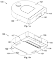
- Fig. 1a the top 121 and Fig. 1b the underside 122 of a cleaning robot 100 as an example of a cleaning device, in particular as an example of a suction device.
- the aspects described specifically for a cleaning robot generally apply to a cleaning device.
- the underside 122 faces the floor to be cleaned or the area of a cleaning area, such as a room, to be cleaned.
- the underside 122 of the cleaning robot 100 typically has one or more drive units 101 (with one or more drive wheels) by means of which the cleaning robot 100 can move independently in order to clean different areas of a floor.
- the cleaning robot 100 can have one or more guide and/or support elements 104 (e.g. non-driven wheels) which enable the cleaning robot 100 to move stably over the floor to be cleaned.
- a Cleaning robot 100 typically has one or more cleaning units 106 (in particular suction nozzles) which are configured to clean the floor beneath the cleaning robot 100.
- a cleaning unit 106 (in particular a suction nozzle) can have a brush roller 102 that is designed to rotate about a rotation axis, wherein the rotation axis is typically arranged parallel to the underside 122 of the cleaning robot 100.
- the brush roller 102 can be used to mechanically loosen dust and/or contaminants on the floor to be cleaned from the floor, so that the dust and/or contaminants can be sucked into the suction mouth 107 of the cleaning unit 106 with increased reliability.
- a user interface can be arranged on the top 121 of the cleaning robot 100, which allows a user of the cleaning robot 100 to make control inputs.
- the cleaning robot 100 can comprise a bumper 105 on a side wall 123 (e.g. on a side wall 123 in the front area of the cleaning robot 100), wherein a shock sensor can be arranged on the bumper 105, which is designed to record sensor data that indicate whether or not the cleaning robot 100 has hit an obstacle (e.g. in the direction of movement 120 and/or during a turn and/or when cornering).
- the triggering of the impact sensor (due to the deflection of the bumper 105) by an obstacle can cause the cleaning robot 100 to rotate, for example, about its vertical or vertical axis, which is perpendicular to the floor, and thereby change the direction of movement 120 in order to avoid the obstacle.
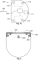
- a cleaning robot 100 typically has one or more environmental sensors 110 (see Fig. 1c ) which are set up to record environmental or sensor data relating to the environment of the cleaning robot 100.
- the one or more environmental sensors 110 can comprise: one or more image cameras, one or more ultrasonic sensors, one or more tactile and/or optical distance sensors, one or more acoustic sensors, one or more temperature sensors, one or more lidar and/or radar sensors, etc.
- a control unit 130 of the cleaning robot 100 can be set up to generate digital map information relating to the area to be cleaned based on the environmental data. cleaning area and, if necessary, store it on a storage unit 111 of the cleaning robot 100.
- the cleaning robot 100 can use the digital map information to orient itself within the cleaning area (e.g. within a room) and/or to determine a route for cleaning the cleaning area.
- the cleaning robot 100 can comprise, in particular, a camera as an environment sensor 110, which is set up to capture image data relating to the environment of the cleaning robot 100.
- the camera can be installed, for example, behind a protective window 150, wherein the protective window 150 can be integrated into the bumper 105.
- Fig. 2 shows an exemplary camera 200 with a specific detection range (in particular field of view) 201, wherein the protective window 150 is arranged (at least partially or completely) within the detection range 201 of the camera 200.
- Fig. 2 a bumper 105, which is movably mounted on the cleaning robot 100, e.g. via one or more spring elements 202.
- a camera 200 that captures the surroundings of the cleaning robot 100 through a window 150 connected to the bumper 105 can be used to efficiently and precisely determine position information with respect to the position of the bumper 105. This also makes it possible to dispense with the installation of an additional impact sensor.
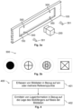
- a plurality of reference points 300 can be arranged in the detection area 201 of the camera 200.
- a reference point 300 can be arranged on the window 150, eg as a marking on the window.
- a reference point can be arranged on the frame of the window 150 or can be formed by the frame of the window 150.
- four reference points 300 are arranged as markings at different locations on the window 150. The individual reference points 300 are thus firmly connected to the bumper 105, so that a change in the position of the bumper 105 leads to a corresponding change in the position of the reference points 300.
- the individual reference points 300 can be designed such that the reference points 300 can be detected by the camera 200 even in the dark.
- the cleaning robot 100 can comprise one or more lighting elements 301 which are designed to illuminate the one or more reference points 300.
- Fig. 3b shows exemplary embodiments of reference points 300.
- the individual reference points 300 are preferably designed such that the individual reference points 300 can be reliably recognized within the images captured by the camera 200.
- the control unit 130 of the cleaning robot 100 can be configured to use the camera 200 to capture one or more images in relation to the reference points 300 connected to the bumper 105.
- the one or more images can be analyzed using an image analysis algorithm to determine one or more properties (in particular the position and/or the size) of the reference points 300 within the one or more captured images.
- the position of the bumper 105 can in turn be deduced from the one or more properties of the reference points 300.
- the front camera 200 of a cleaning robot 100 can thus be used to detect and/or evaluate the movement of the bumper 105 (i.e. the bumper) triggered by a collision.
- the camera 200 can track markings 300 (i.e. reference points) on a window 150 in the bumper 105, from whose positions the position of the bumper 105 can be derived.
- markings 300 on the window instead of markings 300 on the window, the pose of the window frame itself can be tracked by the camera 200.
- the window frame then represents a set of reference points 300.
- the cleaning robot 100 can comprise a dry cleaning unit 106 (with suction fan, filter, dust container, suction mouth 107, and/or brush roller 102) and/or a wet cleaning unit (with water tank, pump, and/or wiping pad).
- At least one camera 200 is housed in the front area of the cleaning robot 100, which can be used for video streaming, environmental mapping and/or object recognition, for example. can be used. With video streaming, the user can follow live what the cleaning robot 100 is currently seeing in front of them.
- the mapping is carried out to measure the surroundings of the cleaning robot 100 and, for example, to determine the location and size of rooms to be cleaned.
- the object recognition is used to detect, evaluate and/or classify objects and obstacles in front of the cleaning robot 100 in order to be able to avoid shoes, cables or chair legs, for example.
- the front of the cleaning robot 100 is formed by a bumper 105, which is movably attached to the housing of the cleaning robot 100.
- a transparent window 150 is typically integrated in the bumper 105, in the viewing cone 201 of the camera 200.
- the viewing cone 201 of the camera 200 typically remains within the area of the transparent window 150 even when the bumper 105 moves relative to the housing of the cleaning robot 100, i.e. when the bumper 105 moves relative to the camera 200.
- the window frame is used to record the movement of the bumper 105, it is preferably arranged completely in the viewing cone 201 of the camera 200, at least in the neutral position.
- the transparent window 150 in the bumper 105 is provided with at least one marking 300.
- the one or more markings 300 can be glued on as stickers, applied as paint or engraved using a laser or engraving machine.
- the one or more markings 300 are within the field of view 201 of the camera 200, so that the markings 300 can be read from the image data of the camera 200.
- the one or more markings 300 are therefore preferably relatively small and preferably positioned in the edge area of the image captured by the camera 200.
- the image edges of the respective captured image can be cropped in order to remove the one or more markings 300 from the individual images and thus to avoid the user being disturbed by the one or more markings 300.
- the one or more markings 300 can take on any shape, size and/or configuration. Preferably, the one or more markings 300 are no larger than required for the resolution and/or image sharpness of the camera 200.
- the one or more markings 300 are preferably designed such that a corresponding image processing algorithm can reliably detect and/or track the one or more markings 300 in the image data (captured by the camera 200), can determine their exact position and/or - depending on the implementation - can determine their size or their deformation in the image data. This can be an optical deformation of one or more markings 300, which results from the spatial position of the one or more markings 300 being changed relative to the camera 102.
- the one or more markings 300 can each be provided with an edge which separates the individual markings 300 in a particularly significant manner from a background of the image. This can be a simple, uniformly colored border, for example white.
- the focus range of the camera 200 used generally only begins at a certain distance in front of the bumper 105. This can lead to the one or more markings 300 not being able to be resolved sharply by the camera 200. It is typically possible for an image analysis algorithm to recognize the one or more markings 300 even with a certain degree of blurriness, in particular if the structures on the one or more markings 300 are sufficiently strong and/or wide.
- a marking 300 is a single-colored, e.g. black, circle. Its position can be reliably determined even in a relatively blurred image by determining the center of gravity of all assigned pixels and enables the marking 300 to be further reduced in size. The edge around the marking 300 enables the relatively blurred marking contour to be distinguished from the actual image content (which typically represents the surroundings of the cleaning robot 100).
- relatively large and/or linear structures can be used, such as lines parallel to the image edges or a frame in the form of a square that runs around the entire image.
- the movement of the bumper 105 is determined by evaluating the marking positions and, if applicable, their location and/or size.
- a lateral transverse movement of the bumper 105 leads to a horizontal movement of the markings 300 (i.e. the reference points)
- a longitudinal movement of the bumper 105 due to a frontal impact leads to a displacement of the markings 300 (i.e. the reference points) away from the center of the image and outwards.
- a rotation of the bumper 105 about its vertical axis leads (if applicable only) on the side of the image on which the bumper 105 is pressed towards the cleaning robot 100, to one or more markings 300 (i.e. reference points) being pushed outwards from the center of the image.
- the evaluation of all types of movement is thus possible if markings 300 are in several different areas of the image (e.g. on the left and right edges).
- the minimum number of markers 300 is one, especially if such a marker is large or long enough - for example a frame around the image.
- the corner points can be tracked and/or the course of the connecting lines can be evaluated.
- the position information can be determined with respect to up to 6 degrees of freedom.
- the degrees of freedom applicable to the bumper 105 can be extracted from geometry data for the cleaning robot 100 or can be included in the calculations as boundary conditions.
- the bumper movement or bumper position can be determined using a look-up table in which various configurations of bumper positions and marking positions have previously been entered.
- the displacement of a marking 300 can be viewed as a superposition of different cases, so that preferably several markings 300 are always viewed simultaneously, which can be done in the form of a matrix equation system (i.e. generally by an assignment function).
- the size of the window can be selected so that the non-transparent area of the bumper 105 surrounding the window 150 - i.e. the window frame - is in the detection area 201 of the camera 200.
- the detection of the bumper movement is carried out, for example, analogously to the use of a rectangular marking 300 in the edge area of the window 150.
- Any markings 300 e.g. a rectangular line on the window frame, can be applied to the window frame and window area.
- the use of the window frame has the advantage that this type of detection is not visible to the user and thus has a reduced influence on the external appearance of the cleaning robot 100.
- the size of the usable image may be reduced when the window frame is used.
- a particularly high level of accuracy in determining the current position and/or location of the bumper 105 can be achieved by means of calibration. This can take place when the cleaning robot 100 is checked at the factory after it has been assembled. In a calibration routine, the bumper 105 can be pressed in in a defined manner while the camera 200 measures the displacement of the bumper 105. In this way, a look-up table can be determined and/or extreme positions of the bumper 105 can be determined so that interpolation can be carried out between them. Another form of calibration can take place every time the cleaning robot 100 is started (e.g. after a restart or before each start of a cleaning job).
- the cleaning robot 100 calibrates the starting and/or rest position of the bumper 105 or the positions of the markings 300 in the image of the camera 200 that correspond to the starting and/or rest position. In this way, a change in the spring characteristics of the springs 202 over the service life, a distortion of the materials of the housing of the cleaning robot 100 and/or the bumper 105 and/or changes due to interim disassembly and assembly can be compensated.
- the camera 200 may no longer be able to detect its surroundings.
- the markings 300 and/or the window frame i.e., the reference points 300 in general
- the markings 300 and/or the window frame can be illuminated from the inside.
- One or more LEDs 301 can be used for this purpose, which may already be present on the circuit board of the camera 200 or the adjacent electronics.
- the markings 300 can be illuminated in white, green, blue or red, for example, so that the markings 300 stand out sufficiently brightly from the background and can therefore be recognized.
- Fig. 4 shows a flow chart of a (possibly computer-implemented) method 400 for determining position information with respect to the position of a bumper 105 (ie Bumpers) which is movably mounted on a cleaning device 100, in particular on a cleaning robot.
- the method 400 can be carried out by a control unit 130 of the cleaning device 100.
- the method 400 includes capturing 401, using a camera 200 of the cleaning device 100, image data relating to one or more reference points 300 connected to the bumper 105.
- Exemplary reference points 300 are markings on a viewing window 150 of the bumper 105 and/or the frame of a viewing opening of the bumper 105.
- the method 400 further includes determining 402 the position information relating to the position of the bumper 105 based on the image data (typically using a previously determined and/or calibrated mapping function).
- the evaluation by means of image processing enables a fine-grained or continuous position determination.
- even relatively small movements of the bumper 105 can be recorded using the camera 200.
- the reaction time of the cleaning robot 100 can thus be reduced and/or a relatively earlier braking of the cleaning robot 100 can be brought about, whereby the impact force of the cleaning robot 100 and possible damage can be reduced.
Landscapes
- Engineering & Computer Science (AREA)
- Mechanical Engineering (AREA)
- Computer Vision & Pattern Recognition (AREA)
- Physics & Mathematics (AREA)
- General Physics & Mathematics (AREA)
- Theoretical Computer Science (AREA)
- Control Of Position, Course, Altitude, Or Attitude Of Moving Bodies (AREA)
Applications Claiming Priority (1)
| Application Number | Priority Date | Filing Date | Title |
|---|---|---|---|
| DE102023208117.2A DE102023208117A1 (de) | 2023-08-24 | 2023-08-24 | Steuereinheit und Verfahren zur Ermittlung der Lage eines Stoßfängers |
Publications (2)
| Publication Number | Publication Date |
|---|---|
| EP4512294A1 true EP4512294A1 (fr) | 2025-02-26 |
| EP4512294B1 EP4512294B1 (fr) | 2026-04-29 |
Family
ID=91738551
Family Applications (1)
| Application Number | Title | Priority Date | Filing Date |
|---|---|---|---|
| EP24184917.3A Active EP4512294B1 (fr) | 2023-08-24 | 2024-06-27 | Unité de commande et procédé de détermination de la position d'un pare-chocs |
Country Status (3)
| Country | Link |
|---|---|
| US (1) | US20250069260A1 (fr) |
| EP (1) | EP4512294B1 (fr) |
| DE (1) | DE102023208117A1 (fr) |
Citations (3)
| Publication number | Priority date | Publication date | Assignee | Title |
|---|---|---|---|---|
| US20140124004A1 (en) * | 2012-11-02 | 2014-05-08 | Irobot Corporation | Autonomous Coverage Robot |
| US20220167815A1 (en) * | 2019-03-26 | 2022-06-02 | Lg Electronics Inc. | Robot cleaner |
| EP4223200A2 (fr) * | 2014-07-01 | 2023-08-09 | Samsung Electronics Co., Ltd. | Robot de nettoyage et son procédé de commande |
Family Cites Families (1)
| Publication number | Priority date | Publication date | Assignee | Title |
|---|---|---|---|---|
| DE102017208962B3 (de) * | 2017-05-29 | 2018-11-15 | BSH Hausgeräte GmbH | Reinigungsroboter mit einem Zusatzmittel zur Veränderung der optischen Eigenschaften einer Kameraoptik |
-
2023
- 2023-08-24 DE DE102023208117.2A patent/DE102023208117A1/de active Pending
-
2024
- 2024-06-27 EP EP24184917.3A patent/EP4512294B1/fr active Active
- 2024-08-23 US US18/813,370 patent/US20250069260A1/en active Pending
Patent Citations (3)
| Publication number | Priority date | Publication date | Assignee | Title |
|---|---|---|---|---|
| US20140124004A1 (en) * | 2012-11-02 | 2014-05-08 | Irobot Corporation | Autonomous Coverage Robot |
| EP4223200A2 (fr) * | 2014-07-01 | 2023-08-09 | Samsung Electronics Co., Ltd. | Robot de nettoyage et son procédé de commande |
| US20220167815A1 (en) * | 2019-03-26 | 2022-06-02 | Lg Electronics Inc. | Robot cleaner |
Also Published As
| Publication number | Publication date |
|---|---|
| DE102023208117A1 (de) | 2025-02-27 |
| US20250069260A1 (en) | 2025-02-27 |
| EP4512294B1 (fr) | 2026-04-29 |
Similar Documents
| Publication | Publication Date | Title |
|---|---|---|
| DE102012221563B4 (de) | Funktionsdiagnose und validierung eines fahrzeugbasierten bildgebungssystems | |
| EP1888382B1 (fr) | Procede et dispositif de commande d'une installation de lavage de vehicules | |
| DE212020000803U1 (de) | Intelligente Reinigungsvorrichtung | |
| DE112017000816T5 (de) | Fahrerassistenzsystem mit variabler Bildauflösung | |
| DE102013110581A1 (de) | Vorrichtung zum optischen Abtasten und Vermessen einer Umgebung | |
| DE10102884A1 (de) | Seitenüberwachungsvorrichtung für ein Kraftfahrzeug | |
| DE112014007047B4 (de) | Fahrzeugkamera-Steuervorrichtung | |
| DE102013019138A1 (de) | Verfahren zum Erkennen eines verdeckten Zustands einer Kamera, Kamerasystem und Kraftfahrzeug | |
| DE102010042026B4 (de) | Verfahren zum Erzeugen eines Abbildes mindestens eines Objekts in einer Umgebung eines Fahrzeugs | |
| DE102016101552A1 (de) | Verfahren zum Erstellen einer Umgebungskarte für ein selbsttätig verfahrbares Bearbeitungsgerät | |
| DE19860676A1 (de) | Visualisierungseinrichtung für die von wenigstens einem Scheinwerfer eines Fahrzeugs bewirkte Beleuchtung vor dem Fahrzeug | |
| WO2012103999A1 (fr) | Dispositif et procédé de prise de vue optique du dessous de caisse d'un véhicule | |
| DE102017223160A1 (de) | Verfahren zum Erkennen von zumindest einem an einem Kraftfahrzeug anliegenden Objekt sowie Steuervorrichtung und Kraftfahrzeug | |
| DE19539642A1 (de) | Verfahren zur Visualisierung eines nicht unmittelbar einsehbaren Überwachungsraumes insbesondere bei einem Fahrzeug, und Vorrichtung zur Visualisierung eines nicht unmittelbar einsehbaren Überwachungsraumes | |
| DE102017108194A1 (de) | Verfahren zum Betrieb eines sich selbsttätig fortbewegenden Fahrzeugs | |
| DE102005056616B4 (de) | Fahrzeugumgebungsüberwachungsvorrichtung | |
| DE102012015282B4 (de) | Verfahren zur Detektion eines verdeckten Zustands einer Bilderfassungseinrichtung eines Kraftfahrzeugs, Kamerasystem und Kraftfahrzeug | |
| DE102020133506A1 (de) | Parkplatzsteuerungssystem, Parkplatzsteuerungsverfahren und Programm | |
| DE102017212370A1 (de) | Verfahren und Vorrichtung zum Identifizieren von Schäden in Fahrzeugscheiben | |
| DE102015007794A1 (de) | Verfahren und Vorrichtung zur Erfassung von Feuchtigkeit und/oder einer Verschmutzung auf einer Außenseite einer Abdeckung eines Bildsensors | |
| EP3833576B1 (fr) | Systeme de camera de surveillance | |
| EP4512294B1 (fr) | Unité de commande et procédé de détermination de la position d'un pare-chocs | |
| WO2019072570A1 (fr) | Vue améliorée de l'environnement d'un véhicule automobile | |
| DE102019116004A1 (de) | Verfahren und vorrichtung zur objekterkennung in blindzonen einer kamera | |
| DE102018205965A1 (de) | Verfahren und Steuergerät zum Kennzeichnen einer Person |
Legal Events
| Date | Code | Title | Description |
|---|---|---|---|
| PUAI | Public reference made under article 153(3) epc to a published international application that has entered the european phase |
Free format text: ORIGINAL CODE: 0009012 |
|
| STAA | Information on the status of an ep patent application or granted ep patent |
Free format text: STATUS: THE APPLICATION HAS BEEN PUBLISHED |
|
| AK | Designated contracting states |
Kind code of ref document: A1 Designated state(s): AL AT BE BG CH CY CZ DE DK EE ES FI FR GB GR HR HU IE IS IT LI LT LU LV MC ME MK MT NL NO PL PT RO RS SE SI SK SM TR |
|
| STAA | Information on the status of an ep patent application or granted ep patent |
Free format text: STATUS: REQUEST FOR EXAMINATION WAS MADE |
|
| 17P | Request for examination filed |
Effective date: 20250826 |
|
| GRAP | Despatch of communication of intention to grant a patent |
Free format text: ORIGINAL CODE: EPIDOSNIGR1 |
|
| STAA | Information on the status of an ep patent application or granted ep patent |
Free format text: STATUS: GRANT OF PATENT IS INTENDED |
|
| INTG | Intention to grant announced |
Effective date: 20260102 |
|
| GRAS | Grant fee paid |
Free format text: ORIGINAL CODE: EPIDOSNIGR3 |
|
| GRAA | (expected) grant |
Free format text: ORIGINAL CODE: 0009210 |
|
| STAA | Information on the status of an ep patent application or granted ep patent |
Free format text: STATUS: THE PATENT HAS BEEN GRANTED |
|
| AK | Designated contracting states |
Kind code of ref document: B1 Designated state(s): AL AT BE BG CH CY CZ DE DK EE ES FI FR GB GR HR HU IE IS IT LI LT LU LV MC ME MK MT NL NO PL PT RO RS SE SI SK SM TR |
|
| REG | Reference to a national code |
Ref country code: CH Ref legal event code: F10 Free format text: ST27 STATUS EVENT CODE: U-0-0-F10-F00 (AS PROVIDED BY THE NATIONAL OFFICE) Effective date: 20260429 |